Isokern STANDARD 36 Owner's Manual
Fireplace with fire-lite application and dm chimney system
Hide thumbs
Also See for STANDARD 36:
Table of Contents
Advertisement
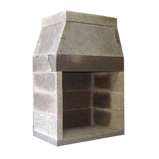
Isokern® STANDARD® Fireplace
Installation, Operation, Maintenance and Owner's Manual
A PRODUCT OF EARTHCORE INDUSTRIES, LLC.
Important: This manual contains assembly rules, installation steps, guidelines, use and maintenance in-
structions for the STANDARD Series fireplace, DM 54 chimney system, and Fire-Lite Application with
the FTF-13 Chimney System. This manual must become the property of and be reviewed by all current and
future users of this product. It is the responsibility of the general contractor and the installer of this product
to ensure that the instructions in this manual are followed exactly and, further that any allowed gas log ap-
pliance used in this product be installed in strict accordance with NFPA 58, NFPA 54/ANSI Z223.1 and the
gas log manufacturer's explicit installation, sizing and operation instructions. It is the responsibility of the
general contractor to provide adequate clearances from all firebox surfaces as specified in this manual.
Be Sure to Read Entire Manual Before Beginning Construction.
Contents of this manual may change without prior notification.
THIS FIREPLACE IS DESIGNED for USE with
SOLID WOOD LOGS, PLUMBED PROPANE
WARNING: If the information in this manual is not followed exactly, a fire or explosion may
result causing property damage, personal injury or loss of life.
SBCCI NO. 9626
ICC Report NO. ESR-2316
IBC 2006, IRC 2006, IMC 2006
THIS MANUAL CAN ONLY BE REPRODUCED IN ITS ENTIRETY
with Fire-Lite Application
and DM Chimney System
STANDARD Models 36, 42 & 46
INSTALLER: Leave this manual with the appliance
CONSUMER: Retain this manual for future reference
(LP) or NATURAL GAS (NG), ONLY
INTERTEK TESTING SERVICES REPORT NO. 3159656MID-008
NYC-MEA 241-90-E
LA RR NO. 25483
Issued: December, 2009
Revision: 003
© 2007 Earthcore Industries, L.L.C.
Advertisement
Table of Contents

Related Manuals for Isokern STANDARD 36


Summary of Contents for Isokern STANDARD 36
- Page 1 Isokern® STANDARD® Fireplace with Fire-Lite Application and DM Chimney System Installation, Operation, Maintenance and Owner’s Manual STANDARD Models 36, 42 & 46 A PRODUCT OF EARTHCORE INDUSTRIES, LLC. Important: This manual contains assembly rules, installation steps, guidelines, use and maintenance in- structions for the STANDARD Series fireplace, DM 54 chimney system, and Fire-Lite Application with the FTF-13 Chimney System.
-
Page 2: Table Of Contents
TABLE OF CONTENTS General Information ............................Intended Use Statement ............................Safety Instructions .............................. Warnock-Hersey Listing Label ........................... Assembled Firebox & Smoke Dome Dimensions ....................Component List & Dimensions .......................... Required Clearance to Combustibles ......................... Rough Framing Dimensions & Corner Location Layout ................... Assembly Instructions .......................... -
Page 3: General Information
Isokern fireplace and chimney system. The FTF-13 or a masonry adhesive. equivalent chimney system only must be used with the Fire-Lite The parts of the STANDARD fireplace and DM 54 application. -
Page 4: Intended Use Statement
Isokern is not responsible for other construction work around the fireplace unit. WARNING: This fireplace has not been tested for use with glass doors. -
Page 5: Safety Instructions
As a result, creosote residue accumulates on 13. When in doubt about a component’s usability - has vis- the flue lining. When ignited this creosote makes an extremely ible or suspected physical damage - consult your Isokern hot fire. distributor or authorized Isokern representative for advice. -
Page 6: Warnock-Hersey Listing Label
FIGURE 1 Isokern Fireplace and Chimney Systems are tested and listed to UL standards: UL 127, ULC S610, and UL 103HT. The listing label shown in Figure 1 above outlines the listed clearances to combustibles and indicates that the units are suitable for use with solid fuel or listed gas appliances. -
Page 7: Assembled Firebox & Smoke Dome Dimensions
Assembled Firebox & Smoke Dome Dimensions 36, 42 & 46 SIDE VIEW PLAN VIEW FRONT VIEW MODEL MINIMUM FRAMING WEIGHT 43” 25 1/4” 63 1/4“ 31 1/2” 36 1/8“ 27 1/4” 33” 20 1/4” 5” (46”W)x(65”H)x(26 3/4”D) 1205 lbs 49” 25 1/4”... -
Page 8: Component List & Dimensions
Part No. Model Qty 49“ 16” 53” Isokern reserves the right to make changes at any time, without notice in design, materials and specifications and also to discon- tinue styles and products. Please call (800) 642-2920 for an Isokern dealer near you. -
Page 9: Required Clearance To Combustibles
Required Clearance to Combustibles The STANDARD Series fireplace and DM 54 chimney system is tested and listed for installation with “clearance to com- bustibles” as follows: The STANDARD Series firebox side walls and back wall require 1-1/2” clearance. (Figure 2) The smoke dome front wall requires 0”... -
Page 10: Rough Framing Dimensions & Corner Location Layout
Rough Framing Dimensions Rough Framing Dimensions Model Width Height Depth Model 36 46” 65” 27” Model 42 52” 65” 27” Framed Model 46 56” 65” 27” Opening Notes: A. “B” includes the STANDARD 3” thick base plate. “B” is reduced by 3”... - Page 11 (Figure 8) The shims can be inserted under a component to level and align it with adjacent Isokern components. Be sure to re-grout any and all gaps resulting from shim insertion to maintain components to full bearing.
-
Page 12: Assembly Instructions
It may be convenient to dry set the first course of side wall and back wall into place on the Isokern base plate and then to trace their position on the base plate with a pencil. (Figure 11) - Page 13 Assembly Instructions - (cont.) Step 3: Continue assembly of the second, third and fourth courses of the firebox side wall and back wall. Apply mortar to the top of each layer of wall components, set the next course above into place. Be sure to mortar all vertical joints of the side wall to back wall connection when setting each component to its mate.
- Page 14 Assembly Instructions - (cont.) Make sure that the top plate is set so that the flue hole is closer to the Step 7: With the damper beams assembled and mortared back wall of the smoke dome assembly. together, set the cast iron throat damper on top of the Be sure to set the smoke dome top plate flush with damper plate and over the damper plate opening.
-
Page 15: Access Modification
CAUTION: When using the decorative appliance, the fireplace damper must be set in the fully open position. Gas line for gas log sets used in the Isokern firebox can be routed through the side wall, back wall or floor of the firebox by drilling an appropriately sized hole using a masonry drill bit (Figure 18). -
Page 16: Firebrick Installation
Isokern makes no claims as to the performance of fire brick or fire brick mortar(s). It is typical for heat stress cracks to appear in the fire bricks in wood burning fireplaces. -
Page 17: Flush Wall Finish Detail
Flush Wall Finish Detail FRAMING PROTRUDES PAST FIREBOX FRONT DRYWALL FLUSH WITH FIREBOX FRONT FIGURE 25 FIGURE 24 STANDARD Series fireplaces are designed to be installed so that the rough front face of the firebox and smoke dome sit flush to the room face of the rough framing members that create the room wall finish. -
Page 18: Required Clearances (When Sheathing Protrudes Beyond Front Of Firebox)
The manufacturer strongly recommends that wherever possible, all combustible framing materials be kept a minimum of 1-1/2” clearance from the Isokern fireplace unit at the side walls and back walls. It is the responsibility of the General Contractor to insure that listed clearances to combustible framing and to insulation are maintained throughout the construction of the project... -
Page 19: Required Clearance To Combustible Framing
Do not frame a wall in front of the Isokern fireplace unit. When sheathing is installed directly to the front face of the Isokern fireplace unit, be sure that when the required noncombustible finished facing materials are applied that no gaps or voids are left behind the finished facing materials. -
Page 20: Required Clearances To Insulation And Vapor Barriers
When STANDARD fireplace installations are surrounded by walls that are to be insulated, the walls must have enough clearance to the Isokern unit in order to maintain the three inch (3”) minimum clearance to insulation. (Figure 33) Never spray the STANDARD fireplace with any type of sealer, insulation or other material. -
Page 21: Flush Wall Fire Brick Finish Detail
Flush Wall Fire Brick Finish Detail FIGURE 34 Recommended Fire Brick Detail: When drywall is the wall finish at the STANDARD face and flush with the rough face of the STANDARD firebox and damper beam, it is recommended when installing the required fire brick lining to the interior of the firebox, that the leading edge of the fire brick - at the floor and at the side walls of the firebox - be set flush with the STANDARD’s rough firebox front. -
Page 22: Flush Wall Brick Finish Detail
Finish Facing Detail FIGURE 35 Important: Since there is no fire brick set along the top of the STANDARD’s firebox opening, when setting the noncombustible finished facing material (code required and supplied by others) across the top of the firebox opening there may be a gap between the back of the noncombustible finish material and the rough front face of the STANDARD damper plate. -
Page 23: Interior Masonry Veneer Fireplace Finishes & Clearances
Interior Masonry Veneer Fireplace Finishes & Clearances FIGURE 37 FIGURE 36 FIGURE 38... -
Page 24: Masonry Veneer Construction Details
Masonry Veneer Construction Details Brick, stone or other masonry veneer finished fronts to STANDARD fireplaces are possible. Special attention is required with regards to: (1) the placement of the proposed masonry veneer facing and its WOOD (FLAMMABLE) interface with the STANDARD fire brick lining, and SHEATHING (2) Clearance to combustible framing and sheathing from any steel “L”... -
Page 25: Non Combustible Finished Facing Requirements & Clearance To Combustible Trim
Non-combustible Finished Facing requirements & Clearance to Combustible Trim Hearth Extensions: All STANDARD fireplaces shall have hearth extensions of brick, concrete, stone, tile or other code approved noncombustible material. Suitable hearth extension material for the STANDARD fireplace shall be placed on the hearth extension’s noncombustible substrate and must extend to at least twenty inches (20”) in front of the fireplace’s finished opening and must extend to at least twelve inches (12”) beyond... -
Page 26: Concrete Support
See page 29 for Isokern DM chimney component weights. The “footprint” area for each model is as follows: A. Model STANDARD 36 @ 43” x 25 1/4” = 7.54 sq. ft. B. Model STANDARD 42 @ 49” x 25 1/4” = 8.59 sq. ft. -
Page 27: General Information
DM 54 Chimney System: General Information The DM 54 chimney is a dual module, refractory masonry chimney system. It is composed of two precast, mating components, the outer casing block and an inner liner. General Information: This chimney system is designed for installation in accordance with the National Fire Protection Standard for Chimneys and Solid Fuel-Burning Appliances, NFPA 211 and in accordance with codes such as ICC, BOCA Basic/National Codes, theInternational... -
Page 28: Component List & Dimensions
DM 54 Chimney Component List & Dimensions 12" HIGH INNER LINER SMALL CROWN CAP 6" HIGH STARTER INNER LINER LARGE CROWN CAP OUTER CASING OFFSET BLOCK BRICK LEDGE OFFSET BLOCK... -
Page 29: Component Weights
DM 54 Chimney: Component Weights Isokern DM Chimney Weights: Total installed Isokern DM chimney weight will vary according to each specific installation. Total installed chimney weight will be based on the overall height and the configuration of the chimney system. - Page 30 DM 54 Chimney Alignment: Where the chimney run is to be a straight vertical run the DM 54 outer casing block sits directly onto the Isokern smoke dome lid. The DM 54 outer casing block, properly set is intended to be flush with the back face of the firebox smoke dome assembly (Figures 49 &...
-
Page 31: Lateral Support
DM 54 Chimney System: Lateral Support Additionally, a two inch (2”) by four inch (4”) by CAUTION: six feet (6’) minimum pressure treated member (“rat run”) Maintain three inch (3”) minimum clearance to installed on each side of and butted up to the outer casing block insulation from all DM 54 chimney component surfaces. - Page 32 DM 54 Chimney System: Lateral Support (cont.) FIGURE 51 FIGURE 52...
- Page 33 DM 54 Offset Chimney Block: For vertical DM 54 chimney to bypass overhead obstructions, the Isokern offset chimney block is used. Offset blocks are six inch (6”) thick, single module chimney components, measuring twenty-one and one-half inch (21-1/2”) wide by twenty-five inches (25”) long. The fourteen inch hole passes through the block at thirty (30°) degrees.
- Page 34 (Figure 57) Offset block Support Foundations: It is required that every third Isokern offset chimney block in the sequence be supported down to footings via concrete block or steel support columns. (Figure 58)
- Page 35 The total chimney weight above the last offset block will be the total weight of the vertical chimney plus any additional al- lowable loads such as the Isokern brickledge, its related brick or stone veneers, and any crown caps, clay pots or other masonry chimney terminations.
- Page 36 Temporarily leave out the inner liner that fits this outer casing block. Set the Isokern brickledge onto the flat top surface of the outer casing in a full bed of Earthcore Mortar. Be sure to align the four 2-1/2” holes in the brickledge with the matching holes in the outer casing block below it.
-
Page 37: Brick Ledge Installation
All DM 54 chimneys that include the DM 54 brickledge must be reinforced as described above. CAUTION: When using the Isokern brickledge it is required that the Standard firebox/smoke dome assembly include the placement of a 4” by 4” by 3/8” minimum steel angle across the firebox opening. -
Page 38: Brick Ledge Load Capacity
FIGURE 65 Brickledge Veneer Finish and Flashing Details: When applying brick, stone or other masonry veneer to the Isokern brickledge standard good building practices for masonry veneer work should govern weather-proofing details and the placement of flashings. A typical flashing detail would be to field fabricate an aluminum or galvanized sheet metal flashing, approximately thirty-two inches (32”)square with a twenty inch (20”) square... -
Page 39: Crown Caps
The small crown cap is intended for use where DM 54 chimneys are to receive thin veneers and cultured stone that do not require the installation of the Isokern brickledge. The small crown cap is also suitable where DM 54 chimneys are to receive a stucco finish. -
Page 40: Height Requirements
SECTION THRU ROOF Chase enclosures need to be built to local wind load require- ments and shall be structurally independent of the Isokern chimney. As with all chimney installations, avoid overhead obstructions such as trees, power lines, etc. FIGURE 70... -
Page 41: Structural Information
Structural Support The STANDARD firebox/smoke dome assembly has a load capacity that allows for the fireplace system to carry a limited amount of straight, vertical DM 54 chimney sections. The load capacity for each model, stated as maximum DM 54 chimney heights, are as follows: STANDARD Model 36: Max. -
Page 42: Common Chimney Terminations
Common Chimney Terminations Two chimney terminations are offered by Isokern, the DM 54 large crown cap and the DM 54 small crown caps. These are cement crown caps designed to provide a weather cap to the DM 54 chimney system. Their design is typical of the cement caps found on traditional masonry chimneys. -
Page 43: Class A Metal Flue
Class “A” (solid fuel) chimneys as an option. Any Class “A” or UL 103 listed metal chimney system is accetable for use on an Isokern system. (Figure 76) Class “A” Metal Flue Types: The selected factory-built metal chimney for use with... -
Page 44: See-Thru
Specialty Applications - See Thru The STANDARD Series see-thru fireplace is built from the STANDARD Series 36” fireplace and is available in a model 36. Please note that due to the large opening area of a two-sided fireplace this type of fireplace can be difficult to get to reach and to maintain proper drafting. -
Page 45: Two Story Stacked Installations
Specialty Applications - Two Story Stacked Installations General Information: To install one STANDARD fireplace and DM 54 chimney system above another, as in a two story stacked installation, both the upper and lower fireplace installations require a concrete slab that is supported down to footings via concrete or steel support structure. -
Page 46: Specialty Applications
“D” is also the sum of “B” plus “C”. “E” is the height of the STANDARD fireplace chosen for the lower unit and includes the Isokern three inch thick base plate. “E” is sev- enty inches (69 ½” actual) for all of the STANDARD models. -
Page 47: Fire-Lite Application General Information
Fire-Lite Application - General Information General Information: The Fire-Lite is a fireplace designed, tested and listed with the ability to be installed on a combustible floor system. The design and installation require that the system use FTF-13, Class A metal flue, or equivalent. Also the Fire-Lite assembled unit must sit on a raised, noncombustible platform. -
Page 48: Fire-Lite Application - Required Clearance To Combustibles
Fire-Lite Application - Required Clearance To Combustibles The Fire-Lite is tested and listed for installation with “clearance to combustibles” as follows: 2” min. 2” min. Four inches (4”) clearance to the combustible floor. FTF 13 Metal Chimney Zero inch (0”) clearance at the Fire-Lite smoke dome front wall (Figure 86). -
Page 49: Fire-Lite Application - Combustible Floor System
Consult your local structural engineer for proper floor FIGURE 90 system design, sizing and specifications. Isokern is not responsible for structural floor support details for the Fire-Lite fireplace. Unless otherwise noted all floor framing drawings in this manual are merely illustrations... -
Page 50: Fire-Lite Application - Raised Metal Platform
Fire-Lite Application - Raised Metal Platform The noncombustible raised platform must be set with a minimum one and one half inch (1-1/2") clearance to the wall directly behind the Fire-Lite assembly. Raised Platform: Nominal four (4") metal base. (Figure 91).Set the Fire-Lite base plate in a mortar bed on to the non-combus- tible raised platform. - Page 51 Fire-Lite Application - Raised Metal Platform (cont.) 14GA. Metal Chanel with a 3” Dia. Hole Centered in each 12” Cavity 1” Thick Insboard onWood Sub-Floor Air From Exterior Air From Room Floor Joists FIGURE 93...
-
Page 52: Fire-Lite Application - Flush Wall Finish Detail
Fire-Lite Application - Flush Wall Finish Detail FIGURE 94 FIGURE 95 STANDARD Fire-Lite Series fireplaces are designed to be installed so that the rough front face of the firebox and smoke dome sit flush to the room face of the rough framing members that create the room wall finish. (Figure 94) CAUTION: Do not frame a wall in front of the Standard Fire-LiteSeries fire box/smoke dome assembly, as shown in figure 95. -
Page 53: Ftf-13 Or Equivalent Chimney System
FTF-13 or Equivalent Chimney System The Fire-Lite is designed, tested and listed for use with FTF-13 Class A metal chimney system, or equivalent. Do not modify or alter metal flue or metal flue components as this could result in an unsafe and potentially dangerous installation that may cause a serious hazard and void the listings, approvals and the limited warranty of the system. - Page 54 FTF-13 or Equivalent Chimney System (cont.) Installation of the FTF-13 Metal Chimney System for the Fire- Lite: Transition from the Fire-Lite to the FTF-13 Metal Chimney System: The FTF-13 metal flue attaches to the smoke dome’s top plate by use of the AP-ISO masonry anchor plate. The Anchor Plate is fitted with an octagonal base plate to affix it to the smoke dome’s top plate.
-
Page 55: Ftf-13 Or Equivalent Installation Components
FTF-13 Installation Components Round Termination FireStop Spacer (30°) FireStop Spacer Offset/Return Package (30°) Chimney Section Combination Offset Return Elbow Stabilizer Anchor Plate Locking Band... -
Page 56: Summary
3. Log grates are required for burning solid fuel in the Instructions: Isokern fireplace. Grates allow for easy air flow up through It is critical that the Isokern masonry elements in the the burning logs thus creating a more complete and efficient Fire-Lite firebox and smoke dome assembly be dry before fir- burning of the fuel. - Page 57 Isokern does not limit the use of In either case, cover the fireplace opening with a fireplace screens.
-
Page 58: Notes
Notes... - Page 59 ISOKERN is not responsible for misuse or mishandling of components. Nothing in this warranty makes ISOKERN, or any division thereof, liable in any respect for any injury or damage to the building or struc- ture in which the fireplace or chimney system has been installed or to persons or property therein arising out of the use, misuse, or installation of properly manufactured ISOKERN product.
Need help?
Do you have a question about the STANDARD 36 and is the answer not in the manual?
Questions and answers