Table of Contents
Advertisement
Quick Links
A PRODUCT OF EARTHCORE INDUSTRIES, LLC.
INSTALLATION, OPERATION, MAINTENANCE and
IMPORTANT: This manual contains assembly rules, installation steps and guidelines, and use and maintenance
instructions for Isokern B-VENT gas appliances (IBV). This manual must become the property of and be reviewed
by all current and future users of this product. It is the responsibility of the distributor, general contractor and the
installer of this product that the instructions in this manual are followed exactly and, further that the allowed gas
log appliance used in this product be installed in strict accordance with the gas log manufacturer's listing and
explicit installation and operation instructions.
This Listed Top Vented Gas Log Enclosure is
designed for use with Decorative Natural Gas or
WARNING: If the information in this
manual is not followed exactly, a fire or
explosion may result causing property
damage, personal injury or loss of life.
- D o n ot s tore o r u se g asoline o r a ny o ther fl ammable
vapors or liquids in the vicinity of this or any other
appliance.
- WHAT TO DO IF YOU SMELL GAS:
* Do not try to light any appliance.
* Do not touch any electrical switch.
* Do not use any phone in your building.
* Immediately call your gas supplier
from a neighbor's phone. Follow the gas
supplier'sinstructions.
* If you cannot reach your gas supplier,
call the fire department.
THIS MANUAL CAN ONLY BE REPRODUCED IN ITS ENTIRETY
ISOKERN B-VENT FIREPLACE
OWNER'S MANUAL
ISOKERN MODELS IBV-36 and IBV-46
Propane (LP) Gas Appliances, only.
PFS Report No. 09-79
SAP No. 506022-03
- NOT FOR USE WITH SOLID FUEL.
- The flue damper must be in the full open
position when burning the gas logs.
-This appliance complies with National Safety
and is tested and listed to A NSI Z21.50b - 2009 as
vented gas fireplaces.
- Installation and service must be performed
by a locally certified gas service agent, licensed
plumber or the gas supplier.
-Installation must conform to local codes. Check
local codes prior to installation.
In the absence of local codes, installation must
conform with current National Fuel Gas Code,
ANSI Z223.1.
INSTALLER: Leave this manual with the
appliance.
CONSUMER: Retain this manual for future
reference.
© 2009 ECI
Issued: May, 2011
Revision: 003
Advertisement
Table of Contents

Related Manuals for Isokern IBV-36


Summary of Contents for Isokern IBV-36
- Page 1 IMPORTANT: This manual contains assembly rules, installation steps and guidelines, and use and maintenance instructions for Isokern B-VENT gas appliances (IBV). This manual must become the property of and be reviewed by all current and future users of this product. It is the responsibility of the distributor, general contractor and the installer of this product that the instructions in this manual are followed exactly and, further that the allowed gas log appliance used in this product be installed in strict accordance with the gas log manufacturer’s listing and...
-
Page 2: Table Of Contents
Table of Contents General Information ............................Safety Information ............................4-5 Assembled Firebox and Smoke Dome Dimensions................... 6 Component List and Dimensions........................7 Required Component List ..........................8 Required Clearance to Combustibles ......................... 9 Combustible Floor System Loading ........................10 IBV Rough Framing Dimension & Corner Location Layout ................11 IBV Assembly Instructions ..........................12-18 Raised and Flush Hearth ............................13 Access Modifications ............................16... -
Page 3: General Information
General Information IBV Models IBV-36 and IBV-46 are tested and listed by PFS Corp., USA Report No. 09-79 to ANSI Z21.50b-2009b- 2009. The IBV models are top-vented, gas only fireplaces that are listed for use only with the ISOFLAMES Gas Log appliance listed in this installation manual. -
Page 4: Safety Information
Safety Information To prevent performance problems, do not use propane fuel tank WARNING: This product contains or generates chemicals of less than 100 lbs. capacity. known to the state of California to cause cancer or birth defects 6. Do not install the IBV in a mobile home or recreational or other reproductive harm. - Page 5 Safety Information 17. Wherever insulation is used, the fireplace must not be placed directly against it. Keep all insulation and vapor barriers a minimum of three inches (3”) away from all IBV and B-Vent chimney components.
-
Page 6: Assembled Firebox And Smoke Dome Dimensions
Assembled Firebox & Smoke Dome Dimensions Plan View Front View Side View Model Minimum Framing Weight 71 1/4” 36” 43” 31 1/2” 21½” 20¼” 5“ 43” W x 71 1/4” H x 26 3/4”D 1500 lbs. 25¼” 36 1/8” 27 1/4” 53”... -
Page 7: Component List And Dimensions
Component List & Dimensions 2 3/4” Part Fireplace Quantity: Part Fireplace Quantity: No.: Size: No.: Size: 25 1/4” 36” W 36” W 46” W 46” W 16” TOP - SLOPING 25 1/4” Part Fireplace Quantity: No.: Size: 3” 36” W 46”... -
Page 8: Required Component List
Required Component List In addition to the standard IBV modular masonry firebox and smoke dome assembly components the IBV requires particular components necessary to complete the installation and meet the ANSI Z-21.50 listing. The two boxes of special IBV components include the following: IBV Box 1 of 2: 1. -
Page 9: Required Clearance To Combustibles
B: Zero inch (0”) clearance at the Isokern firebox and smoke dome sides and front ;; C: One and one half inches (1-1/2”) clearance at the Isokern firebox and smoke dome back wall ;; D: One inch (1”) minimum air space to combustibles at all B-Vent double wall chimney components’ outer layer. -
Page 10: Combustible Floor System Loading
The floor area for each model is as follows: IBV-46 @ 53” x 25.25” = 9.30 sq. ft. IBV-36 @ 43” x 25.25” = 7.54 sq. ft. Notes: 1. Earthcore is not responsible for structural floor support ... -
Page 11: Ibv Rough Framing Dimension & Corner Location Layout
IBV Rough Framing Dimensions Rough Framing Dimensions Model IBV 36 43” 72”,83”,93” 26 3/4” IBV 46 53” 72”,83”,93” 26 3/4” Framed Opening Notes: 1. “Raised hearth” requires additional rough opening height at “B” equal to the height of the raised hearth detail. -
Page 12: Ibv Assembly Instructions
IBV A ssembly Instructions General A ssembly Instructions: Earthcore Mortar (a thin-set type masonry adhesive) is used to glue all IBV masonry components together during field assembly of the unit. The mortar is supplied dry, in either 15 pound or 50 pound pails. -
Page 13: Raised And Flush Hearth
IBV A ssembly Instructions (cont.) Assembly Steps for IBV firebox and smoke dome: Earthcore Mortar Step 1:The IBV base plate can be set directly on a combustible floor s ystem. S et t he b ase p late l evel i n a b ed o f E arthcore M ortar so that the base plate is in full contact with the underlying floor ... - Page 14 IBV A ssembly Instructions (cont.) Step 2: Set the first course of the firebox back wall and side walls into place on the base plate. (Figure 7) Drill Hole ...
- Page 15 IBV A ssembly Instructions (cont.) Step 5: Once all the firebox wall components are set check the top surface of the firebox for level. Step 6: Begin the smoke dome assembly by setting the rear bottom smoke dome component on top of the firebox back wall assembly in a bed of Earthcore Mortar.
-
Page 16: Access ModiFications
IBV A ssembly Instructions (cont.) Access Modification: 1. Gas Line Feed: These provisions for installation of a gas pipe is only for connection to the included ISOFLAMES decorative gas log set. The ISOFLAMES decorative gas log set incorporates an automatic shutoff device and complies with the Standard for Decorative Gas Appliances for Installation in Vented Fireplaces, ANSI Z21.60. -
Page 17: Fire Brick Installation
Step 2. Start the fire brick at the front edge of the floor of the Isokern firebox, proceeding inward toward the back. Step 3: Apply C -clamp w arning l abel t o c enter fl oor b rick p rior ... -
Page 18: Metal Canopy Installation
IBV A ssembly Instructions (cont.) Metal Canopy Installation: 2 High Temperature Wires The metal canopy, as supplied, is forty five inches (45”) long and fits the IBV models 36 & 46. Field cut the metal High Temperature canopy equally at the perforated lines as required for the 36”... -
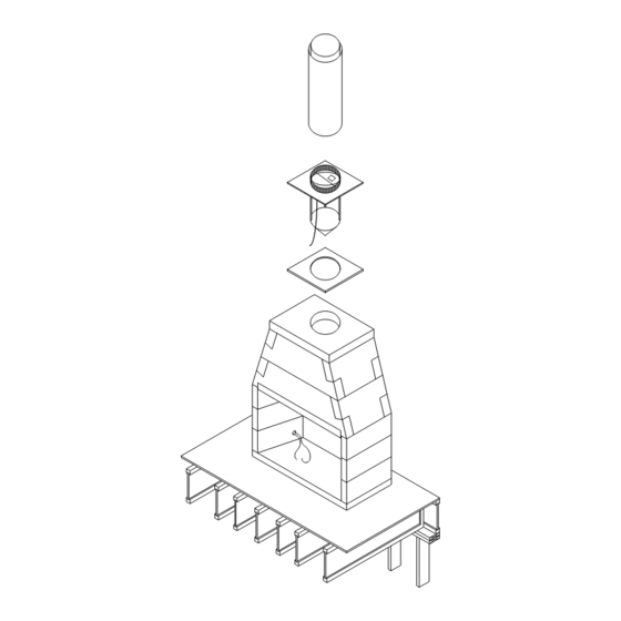
Page 19: Venting Installation
Venting Installation Anchor Plate/ Damper Installation: Listed vent cap Cut a twelve inch (12”) diameter hole in the center of the ceramic fiber blanket which is then placed on the top plate, aligned with and centered on the flue hole in the top plate. The IBV anchor plate assembly is then dropped into the hole in the top plate so that the conical shaped down draft diverter / in-line damper assembly hangs down into the smoke... - Page 20 Venting Installation (cont.) The IBV, per ANSI-Z21.50 standard, requires double wall, gas only B- Vent metal piping for the purpose of venting the appliance to the outside of the building. Specifications: Gas code requirements concerning B-Type vent installations may vary within state, province or local code jurisdictions. Therefore it is recommended that you check with local building codes prior to installing any B-Vent piping for specific requirements or, in the absence of local ...
- Page 21 Venting Installation (cont.) Mechanical Vent Systems: It is acceptable to use mechanical draft systems, if the venting companies do the engineering calculations and make the necessary recommendations for fan size and flue vent diameter following the guidelines of NFPA 211/2006, pg. 211-13. Installation of such systems must also follow the mechanical drafting company’s explicit installation and operation instructions.
-
Page 22: Flush Wall Finish Detail
Figure 24 Figure 25 IBVs are designed to be installed so that the rough front face of the Isokern firebox and smoke dome sit flush to the room face of the rough framing members that create the room wall finish. -
Page 23: Required Clearances (When Sheathing Protrudes Beyond Front Of Firebox)
Figure 27 Combustible wood sheathing such as plywood and particle board may be used to cover the front face of the Isokern smoke dome and be in direct contact with it. Application of such combustible sheathings must assure that the sheathing is held a minimum of eight inches (8”) away from each side of the finished fireplace opening and a minimum of eight inches (8”) inches above the top ... -
Page 24: Flush Wall Fire Brick Finish Detail
Flush Wall Fire Brick Finish Detail Noncombustible Facing Material Figure 28 Recommended Fire Brick Detail: With drywall crossing over the face of the IBV smoke dome assembly (as previously described on p age 2 2), t o c over t he e xposed d rywall t hickness a s w ell a s t o a id i n t he o verall fi t a nd fi nish o f t he I BV f ront, i t i s r ecommended, when installing the required fire brick lining to the interior of the firebox, that the leading edge of the fire brick -... -
Page 25: Finish Facing Detail
(code required and supplied by others) onto the drywall across the top of the firebox opening there will be a gap between the back of the noncombustible finish material and the rough front face of the Isokern Smoke Dome (Figure 29). -
Page 26: Interior Full Masonry Veneer Finished Fireplace Fronts
Masonry Veneer Steel L End of Isokern firebox unit and steel L align Masonry Veneer 4½” 3½” min 8” min Figure 30 Steel L 3 ½” minimum 4” Bearing clearance Isokern unit width dimension Extent of Steel L Figure 31... -
Page 27: Interior Full Masonry Veneer Finished Fireplace Fronts Details
(Figure 33) Figure 32 Steel “L” or angles used to support masonry veneer as it spans the Isokern firebox opening must, in all cases have two inch (2”) clearance to all combustible materials. Note: 1. -
Page 28: Noncombustible Finished Facing Requirements & Clearance To Combustible Trim
(12”) from the top of the fireplace opening. (Figure 35) Adjoining Walls: Side walls and walls to rooms adjoining the Isokern fireplace installation cannot be closer than twenty four inches (24”) to the finished fireplace opening. (Figure 36) Ceilings: The minimum clearance from the top of the fireplace ... -
Page 29: Ibv Pilot Assembly Wiring Diagram
ISO-FLAMES Gas Log Burner Installation The gas control valve is installed on the right side of the ISOFLAMES gas log burner. If the gas supply line comes into the left side of the fireplace, the gas supply line must continue to the right side of the fireplace (as close to the rear fire box wall as possible) and terminate behind the gas valve inlet using rigid 1/2”... -
Page 30: Isoflames Gas Log System Owners Manual
1. READ THESE INSTRUCTIONS COMPLETELY BEFORE USING THE ISOFLAMES GAS LOG SYSTEM. 2. The ISOFLAMES gas log system must be installed in the Isokern B-Vent (IBV) fireplace series. 3. Minimum fireplace opening must adhere to the size chart listed on page 32 of this owner’s manual. -
Page 31: General Information
General Information Tools Required: 1. Adjustable wrench 2. 3/8” flaring tool 3. Open-end wrench (7/16”) 4. Open-end wrench (3/4”) 5. Pipe thread sealer (Non-hardening) 6. Slip-joint pliers (7”) 7. Flat blade screwdriver 8. Pipe wrench (10”) 9. 50/50 soap & water solution 10. - Page 32 Safety Instructions Prior To Installation/Pilot A ssembly Wire Diagram ISOFLAMES FIREPLACE WIDTH FIREPLACE HEIGHT BTU NATURAL GAS BTU LIQUID BURNER MINIMUM PROPANE 24” IBV 36” 30” 50,000 50,000 30” IBV 46” 30” 65,000 65,000 8. Gas supply pressures: GAS SUPPLY PRESSURE NATURAL GAS LIQUID PROPANE Minimum inlet gas supply pressure for the purpose of input adjustment...
- Page 33 Isoflames Gas Log Burner Installation Isokern Gas Burner Installation Instructions 1. MAKE SURE THE FIREPLACE GAS SUPPLY IS TURNED OFF. 2. Place the burner system in the fi replace. Rest it upward, on the front grate fi ngers to expose and allow access to the bottom rear of the burner controls.
-
Page 34: Gas Log Burner Installation
Gas Log Burner Installation (cont.) Isokern Gas Burner Installation Instructions 7. LEAK TEST: Turn on the fi replace gas supply, and test at all connections for leaks using the appropriate soapy water solution. If bubbles appear, a leak is present. Turn off the gas and tighten at all connections. -
Page 35: Isoflames Gas Log Assembly Instructions
ISOFLAMES Gas Log A ssembly Instructions Isokern Log Placement Instructions This instruction contains suggested log placement for the ISO-FLAMES log set. Some fl exibility is possible in log placement to suit your individual preference provided excessive sooting does not result from fl ames striking the logs too directly (see important below). -
Page 36: Isoflames Gas Log Assembly Instructions
ISOFLAMES Gas Log A ssembly Instructions (cont.) LOG LIST 1. Bottom rear log 2. Bottom left log 3. Bottom right log 4. Middle left log 5. Middle center log 6. Middle right log 7. Top left log 8. Top right log LOG PLACEMENT Each log in this gas log set is numbered here to assist in the log placement procedure. -
Page 37: Safety Instruction Before Lighting & Lighting Instructions
Safety Instructions Before Lighting & Lighting Instructions FOR YOUR SAFETY READ BEFORE LIGHTING WARNING: If you do not follow these Instructions exactly, a fire or explosion may result causing property damage, personal injury or loss of life. A. This appliance has a pilot which must be D. - Page 38 Lighting Instructions (cont.) Important: The ISOFLAMES Series gas log system must be installed by a liscensed plumber or gas fitter per code. WARNING: For safe operation of the ISOFLAMES gas log system, a minimum inlet gas supply pressure of 5” w.c. is required for natural gas;;...
-
Page 39: Troubleshooting & Maintenance
Troubleshooting & Maintanence PROBLEM REASON SOLUTION Pilot will not light Air in gas supply line Bleed gas supply line Pilot hood blocked • Check for debris or dirt • Clean pilot Low gas pressure ... -
Page 40: Customer Service & Warranty
ISOFLAMES Customer Service & Warranty Customer Service Earthcore Industries, LLC is committed to customer service and exceeding customer expectations. We are available Monday - Friday 8:30 AM to 4:30 PM EST toll free at 800 642-2920 to provide technical assistance and answer any questions you may have. -
Page 41: Warranty Card
Warranty Card Please cut along dashed lines and send to: Earthcore Industries, LLC 6899 Phillips Industrial Blvd. Jacksonville, Fl 32256 Attn: Technical Department Warranty Card Date of Purchase: __________________________________________________________________________ Name: _________________________________________________________________________________ Address: _________________________________________________________________________________ City, State: _________________________________________________________________________________ Phone No. __________________________________________________________________________________ Gas Log Burner Size: 24”... -
Page 42: Optional Isoflame Wall Switch Instructions
OPTIONAL ISOFLAME WALL SWITCH INSTRUCTIONS Installation Remote 1. Install the wall switch in the desired location within receiver box 15 feet from the burner system in the fi replace. 2. Run the supplied wire from the wall switch to the burner system. -
Page 43: Notes
Notes... - Page 44 Warranty & Disclaimer Isokern Fireplace Earthcore offers a lifetime warranty for all Isokern components, to be free from defects in materials that negatively affect system performance from the date of purchase, subject to the terms and conditions of this limited warranty.
Need help?
Do you have a question about the IBV-36 and is the answer not in the manual?
Questions and answers