Table of Contents
Advertisement
Quick Links
Advertisement
Table of Contents

Subscribe to Our Youtube Channel
Related Manuals for Air Live POE-FSH2422G-250


Summary of Contents for Air Live POE-FSH2422G-250
- Page 1 POE-FSH2422G-250 24 Port 802.3af PoE Web Smart Switch User’s Manual...
- Page 2 OvisLink Corp. has made the best effort to ensure the accuracy of the information in this user’s guide. However, we are not liable for the inaccuracies or errors in this guide. Please use with caution. All information is subject to change without notice All Trademarks are properties of their respective holders. AirLive POE-FSH2422G-250 User’s Manual...
-
Page 3: Fcc Statement
Copyright and Disclaimer FCC Statement Federal Communication Commission Interference Statement This equipment has been tested and found to comply with the limits for a Class B digital device, pursuant to Part 15 of the FCC Rules. These limits are designed to provide reasonable protection against harmful interference in a residential installation. -
Page 4: Table Of Contents
4.7 System IP Configuration (Administrator menu) ............22 4.8 Load default setting (Administrator menu) ............22 4.9 Firmware Update (Administrator menu) ...............23 4.10 Reboot Device (Administrator menu) ..............23 4.11 Port Management....................24 4.12 Port Configuration (Port Management menu) ............24 4.13 Port Mirroring (Port Management menu)............26 AirLive POE-FSH2422G-250 User’s Manual... - Page 5 Table of Contents 4.14 Bandwidth Control (Port Management menu) ............26 4.15 Broadcast Storm Control (Port Management menu) ..........27 4.16 POE (Port Management menu)................28 4.17 VLAN Setting......................28 4.18 VLAN Mode (VLAN Setting) ................29 4.19 VLAN Member (VLAN Setting)................30 4.20 Multi to 1 Setting (VLAN Setting)................31 4.21 Per Port Counter ....................32 4.22 Trunking ......................32 4.23 QoS Setting......................33...
-
Page 6: Introduction
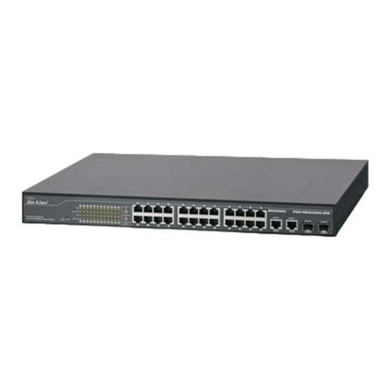
Introduction 1.1 Overview The POE-FSH2422G-250 is a Power Control POE Switch, and total power is 250W. This switch provides 24 10/100Mbps RJ-45 ports and can support 2 Combo Gigabit RJ-45/SFP to uplink. This web-smart switch includes auto-MDI/MDIX crossover detection function. 24 of those ports are all built with PoE functionality, providing the ultimate choice in network flexibility. -
Page 7: Quick Setup
1.3 Quick Setup Power-On the switch The POE-FSH2422G-250 Switch has a built-in power supply to operate with 100 ~ 240V AC, 50 ~ 60Hz power source. The AC power cord connector is located at the rear of the unit and the On/Off switch is next to the connector. -
Page 8: Installation Steps
Connect your device's PoE port to the switch's POE port. The Gigabit ports are not PoE ports. Step 2: Connect your device's PoE port to the switch's POE port (see Figure A). The Gigabit ports are not PoE ports. AirLive POE-FSH2422G-250 User’s Manual... -
Page 9: Comparison Chart
15.4Watts per Port, 250 15.4Watts per Port, Full PoE Power Watts totally Power per Device Dimensions 445 × 220 × 45 mm (L x 440 × 332 × 44 mm (L x W x W x H) AirLive POE-FSH2422G-250 User’s Manual... - Page 10 1. Introduction Weight 2.54 kg 4.7 kg Operating 0 to 45 Temperature Storage -20 to 90 Temperature Humidity 10 to 90% RH (non-condensing) Certifications FCC Class A, CE AirLive POE-FSH2422G-250 User’s Manual...
-
Page 11: Installation Of The Switch
IP address, password, and LED table for user’s reference. 2.1 Unpack the Package Before you begin the installation of POE-FSH2422G-250 Management Switch, make sure that you have all the necessary accessories that come with your package. Follow the steps below to unpack your package contents: Clear out an adequate space to unpack the package carton. -
Page 12: Hardware Overview
These ports also support the automatic MDI/MDIX crossover detection function, providing true “plug and play” capability. Just plug-in the network cable to the hub directly and regardless if the end node is a NIC (Network Interface Card) or switch and hub. AirLive POE-FSH2422G-250 User’s Manual... - Page 13 Note: Be sure that you recorded the setting of your device, else all the setting will be erased when pressing the “Reset” button. The Rear Panel The 3-pronged power plug is placed at the rear panel of the switch right side shown as below. AirLive POE-FSH2422G-250 User’s Manual...
-
Page 14: Installation Site Preparation
2. Installation of the Switch 2.3 Installation Site Preparation You can mount POE-FSH2422G-250 24-Port 802.3af PoE Switch either on desktop or on a 19-inch rack. If you plan to mount the switch on desktop, please choose a steady, level surface in a well-ventilated area that is free from excessive dust. In any case, the installation site chosen for your switch has to comply with the following requirements: The surface where you want to mount the switch must be able to sustain at least 2.5kg. - Page 15 Step 3. Repeat Step 1 and 2 to fasten the bracket on the other side of the switch. Step 4. Mount the unit on the rack and align the notches on both brackets with mounting holes on the rack, and then secure the unit with suitable screws. AirLive POE-FSH2422G-250 User’s Manual...
-
Page 16: Desktop Installation
The 24 RJ-45 station ports and the 1000Base-T ports of the optional Gigabit-Copper module require Cat. 5 twisted-pair UTP/STP cable for connection. When configuring within the 10/100/1000BASE-T cabling architecture, the cable distance should be within 100m. AirLive POE-FSH2422G-250 User’s Manual... -
Page 17: Connecting To Power
Maximum Distance 100 meters 2.7 Connecting to Power POE-FSH2422G-250 PoE Switch features a universal auto-select power supply unit, which allows a power connection to a wide range of input voltages from 100 to 240VAC @ 50 ~ 60Hz. To establish its power connection, simply plug the female end of the power cord into the power connector on the rear of the switch and the male end of the power cord into a suitable power outlet. -
Page 18: Reset To Default
Please take the following steps to reset the Web Smart Switch back to the original default: Step 1. Turn on the POE-FSH2422G-250 PoE Switch. Step 2. Press and hold the reset button continuously for 5 seconds and release the reset button. -
Page 19: Led Indicators
3. LED Indicators LED Indicators Before connecting any network device to POE-FSH2422G-250 802.3af PoE Switch, you should take a few minutes to look over this chapter and get familiar with the front panel LED indicators of your Switch. 3.1 Comprehensive LEDs 3.2 LED Table... -
Page 20: Web Management
4. Web Management Web Management The POE-FSH2422G-250 PoE Switch can be configured by web based interface, including administrator, port management, VLAN setting, per port counter, trunk setting, QoS setting, security filter, configuration/ backup/recovery, miscellaneous, log out, and so on. The device based smart switch supports main stream browsers, such as IE 6.0~7.0, Firefox... - Page 21 Step 3. Double click on the “Internet Protocol (TCP/IP) Step 4. Click on “Use the following IP address” button and enter the computer’s address manually. This IP address must be on the same subnet as the AirLive POE-FSH2422G-250 User’s Manual...
-
Page 22: Remote Management
*Note1: If IP address of the switch is lost, please reset the switch to factory default setting via the reset button. *Note2: The POE-FSH2422G-250 has DHCP client ability. This allows DHCP server (or router) to assign IP automatically. However, we do not recommend turning on the DHCP client because the DHCP server assign the IP randomly. - Page 23 In the diagram above, the router has the WAN (given by the ISP) port IP address “201.100.1.5” and LAN port address “192.168.0.254”. The switch’s IP is “192.168.0.200”. Please follow the instruction below to setup the router and switch for remote access: AirLive POE-FSH2422G-250 User’s Manual...
-
Page 24: Get Into The Web Management
Step 2. Enter the switch’s IP address in the Address field and press enter. Step 3. When prompt for User’s name and Password, enter the following information: User’s Name: admin Password: airlive You should see the following welcome screen after the process is completed: AirLive POE-FSH2422G-250 User’s Manual... -
Page 25: Administrator
In the following sessions, we will talk in detail about the management functions under the Administrator menu. 4.5 Authentication Configuration (Administrator menu) This page shows authentication configuration information. User can set new Username and Password in this page. AirLive POE-FSH2422G-250 User’s Manual... -
Page 26: System Ip Configuration (Administrator Menu)
Gateway: Assign the network gateway for industrial switch. If you change the IP address of this switch and then press Update. It will show “update successfully” then press Reboot button. It will enter user login screen automatically. AirLive POE-FSH2422G-250 User’s Manual... -
Page 27: System Ip Configuration (Administrator Menu)
Clicking the Load button will make the switch bei g set to the original configuration. Note: It exclude to change user name, password and IP configuration. If you want to restore default setting including IP and user name password, then you can press the reset AirLive POE-FSH2422G-250 User’s Manual... -
Page 28: Firmware Update (Administrator Menu)
After pressing Update button, the old web code will be erased. Then you can select the image file and press “update” button to update the firmware you need. 4.10 Reboot Device (Administrator menu) Click Confirm button to reboot the device. AirLive POE-FSH2422G-250 User’s Manual... -
Page 29: Port Management
In the following sessions, we will talk in detail about the management functions under the Port Management menu. 4.12 Port Configuration (Port Management menu) In Port Configuration, you can set and view the operation mode for each port. AirLive POE-FSH2422G-250 User’s Manual... - Page 30 Select Port No.: Tick the check boxes beside the port numbers being set. Click Up date to have the configuration take effect. Current Status: Displays current port status. Setting Status: Displays current status. Clic k Update to make the configuration effective AirLive POE-FSH2422G-250 User’s Manual...
-
Page 31: Port Mirroring (Port Management Menu)
The TX ra te and Rx rate can be filled with the number ranging from 1 to 255. This number sho uld be multiplied by the selected bandwidth resolution to get the actual bandwidth. AirLive POE-FSH2422G-250 User’s Manual... -
Page 32: Broadcast Storm Control (Port Management Menu)
One time unit is 500 us for 10Mbps speed and 5ms for 100Mbps. The excessive broadcast packet will be discarded. For those broadcast packets incoming from the un-selected port, the switch treats it as the normal traffic. AirLive POE-FSH2422G-250 User’s Manual... -
Page 33: Poe (Port Management Menu)
Layer 2 switch. However, all the network devices are still plugged into the same switch physically. There are many management functions can be set or performed if you click the VLAN Setting on Home Page, including: AirLive POE-FSH2422G-250 User’s Manual... -
Page 34: Vlan Mode (Vlan Setting)
Port Based VLAN Mode Add tag means the outgoing packet of the selected port will be inserted a 802.1Q tag. Use this setting for your Up- and Downlink Ports in your VLAN Tagged Network. AirLive POE-FSH2422G-250 User’s Manual... -
Page 35: Vlan Member (Vlan Setting)
Read, and then select or deselect the ports that are on the same VLAN group. In this configuration mode you do not need to worry about defining VLAN groups and VLAN IDs. AirLive POE-FSH2422G-250 User’s Manual... -
Page 36: Multi To 1 Setting (Vlan Setting)
The disable port means the port which will be exc luded in this setting. All ports excluded in this setting are treated as the same VLAN group. In a normal Tag Based VLAN network you will not need this configuration option. AirLive POE-FSH2422G-250 User’s Manual... -
Page 37: Per Port Counter
This managed switch supports two trunk group, each trunk consists of 2~4 ports. Trunk hash algorithm can be selected according to 4 different methods. AirLive POE-FSH2422G-250 User’s Manual... -
Page 38: Qos Setting
There are many management functions can be set or performed if you click the QoS Setting on Home Page, including: Priority Mode Port, 802.1p, IP/DS based TCP/UDP Port Based In the following sessions, we will talk in detail about the management functions under the QoS Setting menu. AirLive POE-FSH2422G-250 User’s Manual... -
Page 39: Priority Mode (Qos Setting)
WRR mode: There are 4 priority queues for Weighted-and-round-robin (WRR) mode. When this mode is selected, the traffic will be forwarded according to the number set in each queue. 5 Port, 802.1p, IP/DS based (QoS Setting) AirLive POE-FSH2422G-250 User’s Manual... -
Page 40: Tcp/Udp Port Based (Qos Setting)
Each port can orrespond to up to 3 MAC addresses. To activate the port binding function, you should enter the correct MAC address, select the port number, and set the port binding to “enable” and then press “update”. AirLive POE-FSH2422G-250 User’s Manual... -
Page 41: Tcp/Udp Filter (Qos Setting)
The ”negative” nction makes the switch drop the selected protocol and forward other protocols. The protocol is checked at the selected secure WAN port. And it should be set at the server side. AirLive POE-FSH2422G-250 User’s Manual... -
Page 42: Spanning Tree
There are many management functions can be set or performed if you click the Spanning Tree on Home Page, including: STP Bridge Settings STP Port Settings Loopback Detection Settin In the following sessions, we will talk in detail about the management functions under the Spanning Tree menu. AirLive POE-FSH2422G-250 User’s Manual... -
Page 43: Stp Bridge Settings (Qos Setting)
BPDU frame. Number between 6-40 (default is 20). Forward Delay: The maximum time (in seconds) the root device will wait before changing states (i.e., discarding to learning to forwarding). Number between 4 – 30 (default is 15) AirLive POE-FSH2422G-250 User’s Manual... -
Page 44: Stp Port Settings (Qos Setting)
4.32 STP Port Settings (QoS Setting) Choose “Port No.” : Port 1 ~ Port 26 Choose “Priority”: 0~ 240 “RPC” = Root Path Cost: 0 = AUTO. When the loop is found, the STP/RSTP will calculate the cost of its path. AirLive POE-FSH2422G-250 User’s Manual... -
Page 45: Loopback Detection Settings (Qos Setting)
The user can save configuration file to a specified file. If the user wants to recover the original configuration, which is saved at the specified path, just enter the password and then press the “upload” button. Finally the original configuration of the switch will be recovered. AirLive POE-FSH2422G-250 User’s Manual... -
Page 46: Miscellaneous
SNMP agents. SNMP agents are programs that reside SNMP capable device's firmware to provide SNMP configuration service. The NMS typically is a PC based software such as HP Openview that can view and manage SNMP network device remotely. AirLive POE-FSH2422G-250 User’s Manual... -
Page 47: Logout
4. Web Management 4.37 Logout The administrator has write access for all parameters governing the onboard agent. User should therefore assign a new administrator password as soon as possible, and store it in a safe place. AirLive POE-FSH2422G-250 User’s Manual... -
Page 48: Appendix A: Product Specifications
48V/DC per Port Output – 15.4W Max per Port – Power Output 24Watt Max Per Port Power 250 Watts (Max) Consumption supply Power 15.4Watts per Device Dimensions 445 × 220 × 45 mm (L x W x H) AirLive POE-FSH2422G-250 User’s Manual... - Page 49 Appendix A: Product Specifications Weight 2.54 kg Operating 0 to 45 Temperature Storage -20 to 90 Temperature Humidity 10 to 90% RH (non-condensing) Certifications FCC Class A, CE AirLive POE-FSH2422G-250 User’s Manual...
-
Page 50: Appendix B: Troubleshooting
Please take the following steps to reset the Web Smart Switch back to the original default: Step 1. Turn on the POE-FSH2422G-250 802.3af PoE Switch Step 2. Press and hold the reset button continuously for 5 seconds and release the reset button. - Page 51 Appendix B: Troubleshooting Key in the user ID and the password to pass the authentication; the user ID and the password are “admin” IP: 192.168.2.1 ID: admin Password: airlvie AirLive POE-FSH2422G-250 User’s Manual...
Need help?
Do you have a question about the POE-FSH2422G-250 and is the answer not in the manual?
Questions and answers