
Subscribe to Our Youtube Channel
Related Manuals for Air Live POE-FSH808PW


Summary of Contents for Air Live POE-FSH808PW
- Page 1 POE-FSH808PW 8-Port 24V Passive POE + 2 Gigabit Uplink Web Smart Switch User’s Manual...
- Page 2 OvisLink Corp. has made the best effort to ensure the accuracy of the information in this user’s guide. However, we are not liable for the inaccuracies or errors in this guide. Please use with caution. All information is subject to change without notice All Trademarks are properties of their respective holders. AirLive POE-FSH808PW User’s Manual...
- Page 3 IMPORTANT NOTE FCC Radiation Exposure Statement: This equipment complies with FCC radiation exposure limits set forth for an uncontrolled environment. This equipment should be installed and operated with minimum distance 20cm between the radiator & your body. AirLive POE-FSH808PW User’s Manual...
-
Page 4: Table Of Contents
4.4.2 System IP Configuration ................20 4.4.3 System Status .................... 20 4.4.4 Load Default Setting .................. 21 4.4.5 Firmware Update ..................22 4.4.6 Reboot Device ................... 22 4.5 Port Management ................22 4.5.1 Port Configuration ..................23 AirLive POE-FSH808PW User’s Manual... - Page 5 4.10.2 STP Port Settings ..................42 4.10.3 Loopback Detection Settings ..............44 4.11 Trunk Setting .................. 45 4.12 Backup/Recovery ................47 4.13 Miscellaneous ................47 4.14 Logout ................... 49 Appendix A: Product Specifications ............50 Appendix B: Troubleshooting..............52 AirLive POE-FSH808PW User’s Manual...
-
Page 6: Introduction
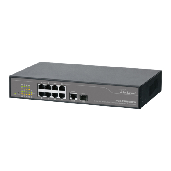
1. Introduction Introduction 1.1 Overview The POE-FSH808PW is a Power Control Passive POE Switch. It was designed for easy installation and high performance in an environment where traffic is on the network and the number of users increases continuously. It consists of 8 10/100Mbps RJ-45 ports and 1 Gigabit RJ-45 plus 1 Gigabit SFP Port. The 8 10/100Mbps RJ-45 ports are built with 24V Passive PoE technology. -
Page 7: Guide To The Chapters
For detailed installation instruction, please see chapter 2 for more information. Power-On the switch The POE-FSH808PW has a built-in power supply to operate with 100 ~ 240V AC, 50 ~ 60Hz power source. The AC power cord connector is located at the rear of the unit and the On/Off switch is next to the connector. -
Page 8: Installation Steps
Step4. Open your web browser and enter "192.168.2.1" to get into the switch's web management. Step5. Enter "admin" for username and "airlive" for password. Step6. Go to "Port Management", and then select "PoE". Step7. Turn on the port number where you connect the device. AirLive POE-FSH808PW User’s Manual... - Page 9 1. Introduction Step8. If you want to install the switch on the 19" rack, please install the mounting kit (optional). Step9. Please see Chapter 4 for further configurations. AirLive POE-FSH808PW User’s Manual...
-
Page 10: Installation Of The Switch
IP address, password, and LED table for user’s reference. 2.1 Unpack the Package Before you begin the installation of POE-FSH808PW Management Switch, make sure that you have all the necessary accessories that come with your package. Follow the steps below to unpack your package contents: 1. -
Page 11: Hardware Overview
These ports also support the automatic MDI/MDIX crossover detection function, providing true “plug and play” capability. Just plug-in the network cable to the hub directly and regardless if the end node is a NIC (Network Interface Card) or switch and hub. AirLive POE-FSH808PW User’s Manual... -
Page 12: Installation Site Preparation
2.3 Installation Site Preparation You can mount POE-FSH808PW either on desktop or on a 19-inch rack. If you plan to mount the switch on desktop, please choose a steady, level surface in a well-ventilated area that is free from excessive dust. In any case, the installation site chosen for your switch has to comply with the following requirements: ... -
Page 13: Rack Mounting
Leave at least 10cm(4 inch) of space around the switch to allow heating dissipation 2.4 Rack Mounting The POE-FSH808PW can be mounted on a standard size 19-inch rack, which can in turn be placed in a wiring closet with other equipments. -
Page 14: Desktop Installation
Attaching the Switch to a 19-inch rack 2.5 Desktop Installation The POE-FSH808PW has four rubber pads attached on each corner of its underside. These pads serve as cushioning against vibration and prevent the switch from sliding off its position. They also allow adequate ventilation space when you place the switch on top of another device. -
Page 15: Cabling Requirements
Auto MDI/MDI-X function The POE-FSH808PW is equipped with Auto-MDI/MDI-X function, which allows you to use straight-thru cable even when connecting to another switch/hub. Simply use the straight-through cable for all types of 10/100BASE-TX connections, either to a PC or to a networking device such as other hub or switch. -
Page 16: Reset To Default
Please take the following steps to reset the Web Smart Switch back to the original default: Step 1. Turn on the POE-FSH808PW. Step 2. Press and hold the reset button continuously for 10 seconds and release the reset button. -
Page 17: Led Indicators
3. LED Indicators LED Indicators Before connecting any network device to POE-FSH808PW, you should take a few minutes to look over this chapter and get familiar with the front panel LED indicators of your Switch. 3.1 Comprehensive LEDs 3.2 LED Table... -
Page 18: Web Management
4. Web Management Web Management The POE-FSH808PW can be configured by web based interface, including administrator, port management, VLAN setting, per port counter, trunk setting, QoS setting, security filter, configuration/ backup/recovery, miscellaneous, log out, and so on. The device based smart switch supports main stream browsers, such as IE, Firefox and Chrome…etc to configure... - Page 19 If there is no network status icon on the task bar, please go to the “Start -> Settings -> Network -> Local Connection” of the task bar’s Start menu. Step 2. Clock on the “property” icon. Step 3. Double click on the “Internet Protocol (TCP/IP) AirLive POE-FSH808PW User’s Manual...
-
Page 20: Remote Management
*Note1: An alternative method is to change the switch’s IP to the same subnet as the computer. *Note2: The POE-FSH808PW has DHCP client ability. This allows DHCP server (or router) to assign IP automatically. However, we do not recommend turning on the DHCP client because the DHCP server assign the IP randomly. - Page 21 Then the Cable provider will assign the switch with a IP and Gateway. When the configuration is finished, the Remote PC can access the switch by typing the switch’s IP address on the web browser. AirLive POE-FSH808PW User’s Manual...
- Page 22 If your router require enter the beginning and ending Port (from PortX to PortX), enter 80 for both. Now the Remote PC will be able to access your switch by entering “201.100.1.5” in the Web browser’s address field. AirLive POE-FSH808PW User’s Manual...
-
Page 23: Get Into The Web Management
The switch’s image on the upper portion of the screen gives the quick overview of the port connection status. When a port is plugged in, the switch’s image will show a “plug” on the corresponding port. AirLive POE-FSH808PW User’s Manual... -
Page 24: Administrator
In the following sessions, we will talk in detail about the management functions under the Administrator menu. 4.4.1 Authentication Configuration This page shows authentication configuration information. User can set new Username and Password in this page. AirLive POE-FSH808PW User’s Manual... -
Page 25: System Ip Configuration
This page is used to check the status of switch, including Switch MAC address and software version. The comment field allows the network administrator to input an easy-to-remember nickname for this switch. The legal characters are “a~z” and “A~Z”, “_”, “-“, “+”, “0 ~9”, excluding special character. AirLive POE-FSH808PW User’s Manual... -
Page 26: Load Default Setting
Configuration Clicking the “Load” button will make the switch being set to the original configuration. *Note: This change only concerns the switch behavior, excluding the change for user name, password and IP configuration. After Load Default is executed, the all settings will be restored to default setting. AirLive POE-FSH808PW User’s Manual... -
Page 27: Firmware Update
Port Management on Home Page, including: Port Configuration Port Mirroring Bandwidth Control Broadcast Storm Control POE Configuration In the following sessions, we will talk in detail about the management functions under the Port Management menu. AirLive POE-FSH808PW User’s Manual... -
Page 28: Port Configuration
Addr. Learning: When the Auto-Negotiation column is set as Disable, users have to set this column as Enable or Disable. Select Port No.: Tick the check boxes beside the port numbers being set. AirLive POE-FSH808PW User’s Manual... -
Page 29: Port Mirroring
Destination port: Theoretically it’s possible to set more than one destination port in a network. Actually the port mirroring function will lower the network throughput, and therefore it’s recommended to set “only one” destination port in a network. AirLive POE-FSH808PW User’s Manual... -
Page 30: Bandwidth Control
This page allows the setting of the bandwidth for each port. The TX rate and Rx rate can be filled with the number ranging from 1 to 255. This number should be multiplied by the selected bandwidth resolution to get the actual bandwidth. AirLive POE-FSH808PW User’s Manual... -
Page 31: Broadcast Storm Control
The switch implements a broadcast storm control mechanism. Tick the check boxes to have them beginning to drop incoming broadcast packets if the received broadcast packet counts reach the threshold defined. Each port’s broadcast storm protection function can be enabled individually by ticking the check boxes. AirLive POE-FSH808PW User’s Manual... -
Page 32: Poe Configuration
While type 10 to port 1, that means 10x2000 packets can be sent in one second. 4.5.5 POE Configuration User could know per PoE port out power status in this page and also enable or disable per port. AirLive POE-FSH808PW User’s Manual... -
Page 33: Vlan Setting
After having switched to Tag Based VLAN Mode, the screen changes. On this screen you can now define and configure your Up and Downlink ports. These are important since here the handover between the switches of your network takes place. AirLive POE-FSH808PW User’s Manual... - Page 34 Remove Tag: Remove tag means the 802.1Q tag of the outgoing packet of the selected port will not be sent. Use this setting for your Network Connections to PCs. Only packets of the VLAN Group the Port is member of will be sent. AirLive POE-FSH808PW User’s Manual...
-
Page 35: Vlan Member
VLAN IDs (Numbers) need to be like on the rest of your network. On other switches you may have the chance to configure names. These are just for your reference. Only the numbers are important! AirLive POE-FSH808PW User’s Manual... - Page 36 Update: Modify the existing VLAN setting. Select the VID, the below settings display, you can change the settings and then press the Update button to update the settings. VLAN Member Port Select: Select the VLAN Member here. AirLive POE-FSH808PW User’s Manual...
- Page 37 If the port joins different VLAN groups, the VID Source Port allows you to define the PVID. After configured and selected, then click on Add to create the table and related port mapping. The new group with its setting will be displayed at the bottom of the screen. AirLive POE-FSH808PW User’s Manual...
-
Page 38: Multi To 1 Setting
4.7 Per Port Counter Port This page provides port counter for each port. There are 4 groups of statistics in total. These 4 categories cannot work simultaneously. Once you change the counter category, the counter will be cleared automatically. AirLive POE-FSH808PW User’s Manual... - Page 39 CRC error. Once your see CRC error increasing here, please notice that there may be hardware issue, the possible reason could be switch port failure, cable lose/broken, cable/fiber connector failure...etc. Update: Select the existing Counter Mode and click Update, the below statistic table will be updated. AirLive POE-FSH808PW User’s Manual...
-
Page 40: Qos Setting
There are many management functions can be set or performed if you click the QoS Setting on Home Page, including: Priority Mode Class of service Configuration In the following sessions, we will talk in detail about the management functions under the QoS Setting menu. AirLive POE-FSH808PW User’s Manual... -
Page 41: Priority Mode
Weighted-and-round-robin (WRR) mode. When this mode is selected, the traffic will be forwarded according to ratio of the number set of Low/High weight user configured. 4.8.2 Port, 802.1p, IP/DS based The page allows you to enable Port Based, VLAN Tag or IP/DS mode of COS. AirLive POE-FSH808PW User’s Manual... -
Page 42: Tcp/Udp Port Based
Select the Option of the Protocol as below figure shown. The Class of Service for TCP/UDP port number allows the network administrator to assign the specific application to a priority queue. F-I-F-O: The incoming packet will be forwarded in first-in-first-out scheme. AirLive POE-FSH808PW User’s Manual... -
Page 43: Security
Each port can correspond to up to 3 MAC addresses. To activate the port binding function, you should enter the correct MAC address, select the port number, and set the port binding to “enable” and then press “update”. AirLive POE-FSH808PW User’s Manual... -
Page 44: Tcp/Udp Filter
The” deny” function makes the switch drop the selected protocol and forward other protocols. The protocol is checked at the selected secure WAN port. And it should be set at the server side. AirLive POE-FSH808PW User’s Manual... -
Page 45: Spanning Tree
The switch supports IEEE 802.1D-2004 RSTP protocol, the RSTP protocol can backward compatible to legacy Spanning Tree Protocol (STP) and 802.1w Rapid Spanning Tree Protocol (RSTP). 4.10.1 STP Bridge Settings The Table allows you to configure STP Mode and the system time settings. AirLive POE-FSH808PW User’s Manual... - Page 46 BPDU frame. Number between 6-40 (default is 20). Forward Delay: The maximum time (in seconds) the root device will wait before changing states (i.e., discarding to learning to forwarding). Number between 4 – 30 (default is 15) AirLive POE-FSH808PW User’s Manual...
-
Page 47: Stp Port Settings
The below table shows the Bridge Status and Root Switch's Status. The Bridge Status shows the STP configuration of the switch. The Root Status shows the Root Switch's Information of the STP domain. 4.10.2 STP Port Settings AirLive POE-FSH808PW User’s Manual... - Page 48 Number between 0 - 200000000. 0 means auto generated path cost. Priority: Show the value of the Port Priority. Ex: 0x80 is 128. State: Show the current port state includes Designated port, Root port or Blocked port. AirLive POE-FSH808PW User’s Manual...
-
Page 49: Loopback Detection Settings
Auto Wake Up: Once the Loopback Detection function is running, the ports maybe disabled to avoid the loop. The Auto Wake Up allows you to activate the port after Time Interval passed. Wake-Up Time Interval: Select the time interval here. Click "Submit" to apply the settings. AirLive POE-FSH808PW User’s Manual... -
Page 50: Trunk Setting
This switch supports one trunk group, port 9 and Port 10. Trunk hash algorithm support Source MAC, Source & Destination MAC Address. AirLive POE-FSH808PW User’s Manual... - Page 51 Activity: This column allows you to select Passive or Active mode. *Note: If you enable LACP on some specified ports and their link partners are normal port without LACP, these specified ports cannot transmit packet to/receive packet from the link partner. AirLive POE-FSH808PW User’s Manual...
-
Page 52: Backup/Recovery
“Update” button. Finally the original configuration of the switch will be recovered. 4.13 Miscellaneous Miscellaneous setting is used to configure output queue aging time, VLAN stride and IGMP snooping. AirLive POE-FSH808PW User’s Manual... - Page 53 Ethernet switch cannot build the separate MAC address table for different VLANs, there will be a conflict of MAC address table. To solve this problem, the switch controller utilizes the VLAN Uplink port to emulate the usage of Independent VLAN MAC Address Table. AirLive POE-FSH808PW User’s Manual...
-
Page 54: Logout
VLAN striding and ignores the VLA 4.14 Logout The administrator has write access for all parameters governing the onboard agent. User should therefore assign a new administrator password as soon as possible, and store it in a safe place. AirLive POE-FSH808PW User’s Manual... -
Page 55: Appendix A: Product Specifications
Web-base Management, Graphic User Interface, Configuration Back and Restore…etc. 1000Mbps port - 1,488,000pps Filtering/Forwarding 100Mbps port - 148,800pps Rates 10Mbps port - 14,880pps 10BaseT Cat. 3, 4, 5 UTP/STP Transmission Media 100BaseTX Cat. 5 UTP/STP 1000BaseT Cat. 5 UTP/STP AirLive POE-FSH808PW User’s Manual... - Page 56 Power Consumption module=180W) Operating:0 to 45℃ Temperature Storage: -20 to 90℃ 10 to 90% RH (non-condensing) Humidity FCC Class A, CE Certifications 44 × 266 × 160 mm (H x W x D) Dimensions 1.8 kg Weight AirLive POE-FSH808PW User’s Manual...
-
Page 57: Appendix B: Troubleshooting
Q: When you forgot your IP or password, please use the reset button for the factory default setting? Please take the following steps to reset the Web Smart Switch back to the original default: Step1: Turn on the POE Switch AirLive POE-FSH808PW User’s Manual... - Page 58 Step3: The switch will reboot for 20 seconds and the configuration of switch will back to the default setting Key in the user ID and the password to pass the authentication as following, IP: 192.168.2.1 ID: admin Password: airlive AirLive POE-FSH808PW User’s Manual...
Need help?
Do you have a question about the POE-FSH808PW and is the answer not in the manual?
Questions and answers