
Related Manuals for Air Live POE-GSH2004L-370


Summary of Contents for Air Live POE-GSH2004L-370
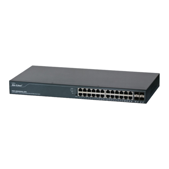
- Page 1 POE-GSH2004L-370 20-Port Gigabit + 4-Port UTP/SFP Combo Active PoE Web Smart Switch User’s Manual...
- Page 2 OvisLink Corp. has made the best effort to ensure the accuracy of the information in this user’s guide. However, we are not liable for the inaccuracies or errors in this guide. Please use with caution. All information is subject to change without notice All Trademarks are properties of their respective holders. AirLive POE-GSH2004L-370 User’s Manual...
-
Page 3: Fcc Statement
Copyright and Disclaimer FCC Statement Federal Communication Commission Interference Statement This equipment has been tested and found to comply with the limits for a Class B digital device, pursuant to Part 15 of the FCC Rules. These limits are designed to provide reasonable protection against harmful interference in a residential installation. -
Page 4: Table Of Contents
4. Web Management ..................16 4.1 Setup your computer for Web management ........16 4.2 Remote Management ................19 4.3 Get Into the Web management ............21 4.4 Configuration ..................22 4.4.1 System Information ................... 23 AirLive POE-GSH2004L-370 User’s Manual... - Page 5 Table of Contents 4.4.2 Ports Configuration ................... 27 4.4.3 VLAN Mode Configuration ................ 30 4.4.4 VLAN Group Configuration ............... 31 4.4.5 VLAN Isolation ..................36 4.4.6 PoE with device guard ................37 4.4.7 Aggregation ....................41 4.4.8 RSTP ......................42 4.4.9 IGMP Snooping ..................
-
Page 6: Introduction
Introduction 1.1 Overview The POE-GSH2004L-370 is a Power Control POE Web Smart Switch, and total power is 370W. This Switch is a standard switch that meets all IEEE 802.3/u/x/z Gigabit, Fast Ethernet specifications. The switch has 20 10/100/1000Mbps TP ports and 4 Gigabit TP/SFP transceiver slots;... -
Page 7: Guide To The Chapters
- 100Mbps LC, Multi-Mode, SFP Fiber transceiver, 2km - 100Mbps LC, Single-Mode, SFP Fiber transceiver, 30km This user’s manual will help you to uncover most functions of the POE-GSH2004L-370 with step-by-step instructions presented by high quality illustrations. Thank you for choosing OvisLink’s product. -
Page 8: Quick Setup
For detailed installation instruction, please see chapter 2 for more information. Power-On the switch The POE-GSH2004L-370 has a built-in power supply to operate with 100 ~ 240V AC, 50 ~ 60Hz power source. The AC power cord connector is located at the rear of the unit and the On/Off switch is next to the connector. -
Page 9: Installation Steps
1.4 Installation Steps This section lists the installation procedures in steps. Each step’s instruction is thoroughly explained in the subsequent sections of following chapter. Step1. Connect your device's PoE port to the switch's POE port (see Figure A). AirLive POE-GSH2004L-370 User’s Manual... - Page 10 Please follow the instructions below. Step4. If you want to install the switch on the 19" rack, please install the mounting kit according to Figure C. Step5. Set your PC's IP address to 192.168.2.50. AirLive POE-GSH2004L-370 User’s Manual...
- Page 11 Step6. Open your web browser and enter "192.168.2.1" to get into the switch's web management. Step7. Enter "airlive" for password. Step8. If you want to install the switch on the 19" rack, please install the mounting kit. Step9. Please see the following chapters for further configurations. AirLive POE-GSH2004L-370 User’s Manual...
-
Page 12: Installation Of The Switch
IP address, password, and LED table for user’s reference. 2.1 Unpack the Package Before you begin the installation of POE-GSH2004L-370 Web smart Switch, make sure that you have all the necessary accessories that come with your package. Follow the steps below to unpack your package contents: 1. -
Page 13: Hardware Overview
10/100Mbps and full- duplex mode for 10/100/1000Mbps. 24 10/100/1000Mbps RJ-45 ports are PoE enable ports. These PoE ports will be automatically activated when a compatible terminal is identified, and the PoE port will supply power to the connected PoE device. AirLive POE-GSH2004L-370 User’s Manual... - Page 14 ※ Note: Be sure that you recorded the setting of your device; else all the setting will be erased when pressing the “Mode” (reset) button 10 seconds. 2.2.2 Rear Panel The 3-pronged power plug and on/off switch are placed at the rear panel of the switch right side shown as below. AirLive POE-GSH2004L-370 User’s Manual...
-
Page 15: Installation Site Preparation
2. Installation of the Switch 2.3 Installation Site Preparation You can mount POE-GSH2004L-370 either on desktop or on a 19-inch rack. If you plan to mount the switch on desktop, please choose a steady, level surface in a well-ventilated area that is free from excessive dust. In any case, the installation site chosen for your switch has to comply with the following requirements: ... - Page 16 Step 4. Mount the unit on the rack and align the notches on both brackets with mounting holes on the rack, and then secure the unit with suitable screws. Fastening the brackets on the switch Attaching the Switch to a 19-inch rack AirLive POE-GSH2004L-370 User’s Manual...
-
Page 17: Desktop Installation
2. Installation of the Switch 2.5 Desktop Installation The POE-GSH2004L-370 has four rubber pads attached on each corner of its underside. These pads serve as cushioning against vibration and prevent the switch from sliding off its position. They also allow adequate ventilation space when you place the switch on top of another device. -
Page 18: Connecting To Power
Auto MDI/MDI-X function The POE-GSH2004L-370 is equipped with Auto-MDI/MDI-X function, which allows you to use straight-through cable even when connecting to another switch/hub. Simply use the straight-through cable for all types of 10/100BASE-TX connections, either to a PC or to a networking device such as other hub or switch. -
Page 19: Reset To Default
Please take the following steps to reset the Web Smart Switch back to the original default: Step 1. Turn on the POE-GSH2004L-370. Step 2. Press and hold the mode (reset) button continuously for 10 seconds and release the mode (reset) button. -
Page 20: Led Indicators
3. LED Indicators LED Indicators Before connecting any network device to POE-GSH2004L-370, you should take a few minutes to look over this chapter and get familiar with the front panel LED indicators of your Switch. 3.1 Comprehensive LEDs 3.2 LED Table... -
Page 21: Web Management
4. Web Management Web Management The POE-GSH2004L-370 can be configured by web based interface, including System Information, Ports Configuration, VLAN setting, Aggregation, QoS setting, PoE, IGMP Snooping, Mirroring, SNMP, Loop Detection, Broadcast Strom, configuration/ backup/recovery, log out, and so on. The device based smart switch supports main stream browsers, such as IE, Firefox and Chrome…etc to configure the device function. - Page 22 The switch’s Default IP IP Address: 192.168.2.1 Subnet Mask: 255.255.255.0 Now if your computer’s IP is not in the same subnet as the switch, please follow the steps below to change the computer’s IP: Figure 4-1 Manual IP setting AirLive POE-GSH2004L-370 User’s Manual...
- Page 23 192.168.2.1 Click “Ok” after finish entering the IP. ※ Note1: The POE-GSH2004L-370 has DHCP client ability. This allows DHCP server (or router) to assign IP automatically. However, we do not recommend turning on the DHCP client because the DHCP server assign the IP randomly. The DHCP client should be used only when connecting directly to Cable Modem (for remote management) whose service provider uses DHCP for IP assignment.
-
Page 24: Remote Management
Go to the console port management to find out what IP has been assigned to the switch. When the configuration is finished, the Remote PC can access the switch by typing the switch’s IP address on the web browser. AirLive POE-GSH2004L-370 User’s Manual... - Page 25 If your router require enter the beginning and ending Port (from PortX to PortX), enter 80 for both. Now the Remote PC will be able to access your switch by entering “201.100.1.5” in the Web browser’s address field. AirLive POE-GSH2004L-370 User’s Manual...
-
Page 26: Get Into The Web Management
Step 2. Enter the switch’s IP address in the Address field and press enter. Step 3. When prompt for and Password, enter the following information: Password: airlive You should see the following welcome screen after the process is completed: AirLive POE-GSH2004L-370 User’s Manual... -
Page 27: Configuration
Aggregation RSTP IGMP Snooping Mirroring QoS Loop Detection Broadcast Strom Protection SNMP In the following sessions, we will talk in detail about the management functions under the Configuration menu. AirLive POE-GSH2004L-370 User’s Manual... -
Page 28: System Information
4. Web Management 4.4.1 System Information System configuration is one of the most important functions. Without a proper setting, network administrator would not be able to manage the device. The switch supports manual IP address setting. AirLive POE-GSH2004L-370 User’s Manual... - Page 29 The serial number is assigned by the manufacturer. Temperature: Show the Temperature of this switch. Voltage: Show the Voltage of this switch. Active IP Address: Show the active IP address of this switch. AirLive POE-GSH2004L-370 User’s Manual...
- Page 30 Set a special name for this switch. Up to 16 characters are allowed in this parameter. Any alphanumeric character and null are acceptable. Default: POE-GSH2004L-370 System Contact: Set a special System Contact name for this switch. Any alphanumeric character and null are acceptable. Default: Ovislink AirLive POE-GSH2004L-370 User’s Manual...
- Page 31 Manually assign the IP address that the network is using. Default: 192.168.2.1 Fallback Subnet Mask: Assign the subnet mask to the IP address. Default: 255.255.255.0 Fallback Gateway: Assign the network gateway for industrial switch. Default: 192.168.2.254 AirLive POE-GSH2004L-370 User’s Manual...
-
Page 32: Ports Configuration
Port Configuration is applied for the settings of the ports on the switch. By this function, you can set or reset the values for Mode and Flow Control. Others you could set the power saving mode for switch power consumption. AirLive POE-GSH2004L-370 User’s Manual... - Page 33 4. Web Management AirLive POE-GSH2004L-370 User’s Manual...
- Page 34 This function support jumbo frames of up to 9600 bytes, Just tick the check box ( ) to enable it. Default: disable Perfect Reach/Power Saving Mode: This function supports Power Saving and perfect Reach, Just select with the Full/ Link-up/ Link-down/ Disable Default: disable Link: Show link status of this port. AirLive POE-GSH2004L-370 User’s Manual...
-
Page 35: Vlan Mode Configuration
1~4094. VLAN configuration is used to divide a LAN into smaller ones. With proper configuration, you can gain not only improved security and increased performance, but also save a lot of VLAN management effort. The VLAN Mode Selection function includes two modes: Port-based, Tag-based. AirLive POE-GSH2004L-370 User’s Manual... -
Page 36: Vlan Group Configuration
The VLAN membership configuration for the selected switch can be monitored and modified here. Up to 4094 VLANs are supported. This page allows for adding and deleting VLANs as well as adding and deleting port members of each VLAN. AirLive POE-GSH2004L-370 User’s Manual... - Page 37 4. Web Management AirLive POE-GSH2004L-370 User’s Manual...
- Page 38 In modify function this is used to enable or disable if a port is a member of the new added VLAN, “Enable” means it is a member of the VLAN. Just tick the check box ( ) beside the port x to enable it. AirLive POE-GSH2004L-370 User’s Manual...
- Page 39 Tag-based VLAN with VID x. For example, if port x receives an untagged packet, the switch will apply the PVID(assume as VID y) of port x to tag this packet, the packet then will be forwarded as the tagged packet with VID Port-based VLAN mode AirLive POE-GSH2004L-370 User’s Manual...
- Page 40 Create a new port-based VLAN or tag-based VLAN, which depends on the VLAN mode you choose in VLAN mode function. Delete Group: Just tick the check box ( ) beside the ID, then press the <Delete> button to delete the group. AirLive POE-GSH2004L-370 User’s Manual...
-
Page 41: Vlan Isolation
A check box is provided for each port of a private VLAN. When checked, port isolation is enabled on that port. When unchecked, port isolation is disabled on that port. By default, port isolation is disabled on all ports. AirLive POE-GSH2004L-370 User’s Manual... -
Page 42: Poe With Device Guard
PD, and it will stop supplying the power once the power required by the PD excesses the Class, Short Circuit or over temperature occurs. PoE Enabled: To evoke to enable which port supply the power to the PD. AirLive POE-GSH2004L-370 User’s Manual... - Page 43 Allocation (W): The power is consumed by the port. Detection: 4-Point, Legacy, Both. Delay time: The delay time of PoE, 0~300seconds, default is 0. Reset: Reset the PoE Port which is select. AirLive POE-GSH2004L-370 User’s Manual...
- Page 44 When the IP is set in the guard IP , the switch will try to ping the IP , if the IP is not reply , the switch will do the failure action. AirLive POE-GSH2004L-370 User’s Manual...
- Page 45 To set the action when PoE device is detected that it is failure. There are two opinion, nothing and reboot. Reboot To set how many time this switch will wait, when reboot is required by device guard. AirLive POE-GSH2004L-370 User’s Manual...
-
Page 46: Aggregation
Fast Ethernet ports. Normal: Set up the ports that do not join any aggregation trunking group. Group 1~8: Group the ports you choose together. Up to 12 ports can be selected for each group. AirLive POE-GSH2004L-370 User’s Manual... -
Page 47: Rstp
BPDU frame. Number between 6-40 (default is 20). Forward Delay The maximum time (in seconds) the root device will wait before changing states (i.e., discarding to learning to forwarding). Number between 4–30 (default is 15) AirLive POE-GSH2004L-370 User’s Manual... - Page 48 4. Web Management AirLive POE-GSH2004L-370 User’s Manual...
-
Page 49: Igmp Snooping
Just tick the check box ( ) to enable this function. Default: disable Router Ports: Just tick the check box ( ) beside the port x to enable router ports, then press the <Apply> button to start up. Default: none AirLive POE-GSH2004L-370 User’s Manual... -
Page 50: Mirroring
For example, we assume that Port A and Port B are Source Ports, and Port C is Mirror Port respectively, thus, the traffic passing through Port A and Port B will be copied to Port C for monitor purpose. AirLive POE-GSH2004L-370 User’s Manual... - Page 51 Set up the port for being monitored. Just tick the check box ( ) beside the port x and valid port is Port 1~24. Mirror Port: Use the drop-down menu to select a mirror port. AirLive POE-GSH2004L-370 User’s Manual...
-
Page 52: Qos
This function will affect the priority of VLAN tag. Based on priority of VLAN tag, it can arrange 0~7 priorities, priorities can map to 4 queues of the switch (low, normal, medium, high) and possess different bandwidth distribution according to your weight setting. AirLive POE-GSH2004L-370 User’s Manual... - Page 53 DSCP can form total 64 (0~63) kinds of Traffic Class based on the arrangement of 6-bit field in DSCP of the IP packet. In the switch, user is allowed to set up these 64 kinds of Class that belong to any of queue (low,normal, medium, high). AirLive POE-GSH2004L-370 User’s Manual...
- Page 54 When Custom is selected for Prioritize Traffic, you may assign specific Port Number for DSCP Configuration. DSCP Configuration: 64 kinds of priority traffic as mentioned above, user can set up any of Queue (low, normal, medium, high). In default, Priority 0~63 are mapping to Queue high. AirLive POE-GSH2004L-370 User’s Manual...
-
Page 55: Loop Detection
The port will be locked when it received the looping detection frames. If you want to resume the locked port, please find out the looping path and take off the looping path, then select “Unlock port” and click on “Apply” to turn on the locked ports. AirLive POE-GSH2004L-370 User’s Manual... -
Page 56: Broadcast Strom Protection
If the broadcast traffic is still higher than, the port will be closed for a period of time again. If the broadcast traffic is under the threshold, the port will re-open and forward the packets normally. AirLive POE-GSH2004L-370 User’s Manual... - Page 57 4. Web Management AirLive POE-GSH2004L-370 User’s Manual...
- Page 58 Controls whether Broadcast Strom Protection is enabled on this switch port. Unlock port: When ticking the port, port locked will be opened and turned into unlocked. If not ticking the port, Port maintains locked. AirLive POE-GSH2004L-370 User’s Manual...
-
Page 59: Snmp
SNMP. A SNMP manager must pass the authentication by identifying both community names, then it can access the MIB information of the target device. So, both parties must have the same community name. Once completing the setting, click <Apply> button, the setting takes effect. AirLive POE-GSH2004L-370 User’s Manual... - Page 60 Default community name for Set: private Default community name for Trap: public System Event: The System Event trap enable here is used for the “Cold Boot” or “Warm Boot” of system Event. Default is “Disable”. AirLive POE-GSH2004L-370 User’s Manual...
-
Page 61: Monitoring
Statistics Overview Detailed Statistics IGMP Status PoE Status Ping 4.5.1 Statistics Overview The section describes to the Port statistics information and provides overview of general traffic statistics for all switch ports. AirLive POE-GSH2004L-370 User’s Manual... -
Page 62: Detailed Statistics
The number of frames received in error and the number of incomplete transmissions per port. 4.5.2 Detailed Statistics Display the detailed counting number of each port’s traffic. In the Fig. 4-20, the window can show all counter information each port at one time. AirLive POE-GSH2004L-370 User’s Manual... - Page 63 Show the counting number of the received multicast packet. Rx Broad- and Multicast: Show the counting number of the received broadcast with multicast packet. Rx Error Packets: Show the counting number of the received error packets. AirLive POE-GSH2004L-370 User’s Manual...
- Page 64 Show the counting number of the transmitted multicast packet. Tx Broad- and Multicast: Show the counting number of the transmitted broadcast with multicast packet. Tx Error Packets: Show the counting number of the received error packets. AirLive POE-GSH2004L-370 User’s Manual...
- Page 65 Number of 1024-max_length-byte frames in good and bad packets received. Tx 64 Bytes: Number of 64-byte frames in good and bad packets transmitted. Tx 65-127 Bytes: Number of 65 ~ 126-byte frames in good and bad packets transmitted. AirLive POE-GSH2004L-370 User’s Manual...
- Page 66 Number of short frames (<64 Bytes) with valid CRC. Rx Oversize: Number of long frames(according to max_length register) with valid CRC. Rx Fragments: Number of short frames (< 64 bytes) with invalid CRC. AirLive POE-GSH2004L-370 User’s Manual...
- Page 67 Number of collisions transmitting frames experienced. Tx Drops: Number of frames dropped due to excessive collision, late collision, or frame aging. Tx Overflow: Number of frames dropped due to the lack of transmitting buffer. AirLive POE-GSH2004L-370 User’s Manual...
-
Page 68: Rstp Status
STP root device. However, if all devices have the same priority, the device with the lowest MAC address will then become the root device. Number between 0 - 61440 in increments of 4096. Therefore, there are 16 distinct values. AirLive POE-GSH2004L-370 User’s Manual... - Page 69 Number between 1-10 (default is 2). Max Age: Show the root bridge’s current max age time. Forward Delay: Show the root bridge’s forward delay time. Topology: Show the root bridge’s spanning tree topology. AirLive POE-GSH2004L-370 User’s Manual...
- Page 70 True, the port is treated as point-to-point link by RSTP and unconditionally transited to Forwarding state. If it is set as False, fast transition to Forwarding state will not happen on this port. Default: Auto Protocol: Show the root bridge’s spanning tree topology AirLive POE-GSH2004L-370 User’s Manual...
-
Page 71: Igmp Status
Show VLAN Id for each multicast group. Querier: Show the group membership queries status. Queries transmitted: To count the group membership queries transmitted. Queries received: To count the group membership queries received. AirLive POE-GSH2004L-370 User’s Manual... - Page 72 It Calculate the number of times of IGMPV3 report. V2 Leaves: When a host leaves a group, it sends a leave group membership message to multicast routers on the network, it show the leaves number. AirLive POE-GSH2004L-370 User’s Manual...
-
Page 73: Poe Status
4. Web Management 4.5.5 PoE Status Display the information about the PoE status. Power Reservation: The watts are supplied by the PoE./ The maximal power that the switch can supply (Read Only). Port No: Port number. AirLive POE-GSH2004L-370 User’s Manual... - Page 74 Current Used: The Power Used shows how much current the PD currently is using. Priority: The Priority shows the port's priority configured by the user. Port Status: The Port Status shows the port's status. AirLive POE-GSH2004L-370 User’s Manual...
-
Page 75: Ping
Total: The sum of the current that every port supplies. 4.5.6 Ping To set up target IP address for ping function and display ping status. In Fig. 4-22, the window shows the ping information. AirLive POE-GSH2004L-370 User’s Manual... - Page 76 Set up a Target IP address to ping. Count: Use drop-down menu to set number of echo requests to send. Four type of number can choose, there are 1, 5, 10 and 20. Default: 1 AirLive POE-GSH2004L-370 User’s Manual...
- Page 77 Show the result of the ping status. Received replies: Show the received replies number of times. Request timeouts: Show the timeout of request. Average Response times (In ms): Show the average response time in milliseconds. AirLive POE-GSH2004L-370 User’s Manual...
-
Page 78: Maintenance
IP address setting to the factory default, please press the “RESET”(mode) button on the front panel. Note for “RESET” (mode) button: You must press the “RESET” (mode) button over 10 seconds to restore the factory default setting. AirLive POE-GSH2004L-370 User’s Manual... -
Page 79: Software Upgrade
4.6.4 Configuration File Transfer You can backup your switch’s configuration file into your computer folder in case accident happens. In addition, uploading backup configuration file into a new or a crashed switch can save much time and avoid mistakes. AirLive POE-GSH2004L-370 User’s Manual... -
Page 80: Logout
If no action and no key is stroke as well in any function screen more than the minutes you set up in Auto Logout Timer, the switch will have you logout automatically. Or press the <Logout> button in Logout function to exit the system manually. AirLive POE-GSH2004L-370 User’s Manual... -
Page 81: Appendix A: Product Specifications
IEEE 802.1d Spanning Tree Protocol IEEE 802.1w Rapid Spanning Tree Protocol Hardware Number of Ports: 24 PSE/Power over Ethernet Ports MAC Address: 8K Buffer Memory: Embedded 512 K Bytes frame buffer Jumbo frames: 9KB Transmission Method: Store and Forward AirLive POE-GSH2004L-370 User’s Manual... - Page 82 Port-based VLAN Port Isolation Management VLAN IGMP v1/v2 Snooping: Supports 64 multicast groups (source-specific multicasting is also supported) Port mirroring Loop detection Broadcast Storm protection Quality of Service(QoS) 8 hardware queues Scheduling AirLive POE-GSH2004L-370 User’s Manual...
- Page 83 100-240 VAC 50~60 Hz, internal , universal Power Output 54V/DC Per Port Output – 30 W Max Per Port Total PoE Output 370 W Power Consumption PoE= 367.2W (Full loading with PD connect) ; System= 17.41W (Full loading without PD) AirLive POE-GSH2004L-370 User’s Manual...
- Page 84 Appendix A: Product Specifications Dimensions 442 (W)x 44 (H) x 211.2 (D) mm Weight 3.6 Kg AirLive POE-GSH2004L-370 User’s Manual...
-
Page 85: Appendix B: Troubleshooting
Please take the following steps to reset the Web Smart Switch back to the original default: Step1: Turn on the Switch Step2: Press and hold the reset button continuously for 10 seconds and release the reset button. AirLive POE-GSH2004L-370 User’s Manual... - Page 86 Step3: The switch will reboot for 30 seconds and the configuration of switch will back to the default setting Key in the user ID and the password to pass the authentication as following, IP: 192.168.2.1 Password: airlive AirLive POE-GSH2004L-370 User’s Manual...
Need help?
Do you have a question about the POE-GSH2004L-370 and is the answer not in the manual?
Questions and answers