Table of Contents
Advertisement
Quick Links
Advertisement
Table of Contents

Subscribe to Our Youtube Channel
Related Manuals for Air Live POE-GSH2624-370


Summary of Contents for Air Live POE-GSH2624-370
-
Page 1: User Manual
POE-GSH2624-370 24 Port Device Manage PoE Switch User Manual... - Page 2 OvisLink Corp. has made the best effort to ensure the accuracy of the information in this user’s guide. However, we are not liable for the inaccuracies or errors in this guide. Please use with caution. All information is subject to change without notice All Trademarks are properties of their respective holders. AirLive POE-GSH2624-370 User Manual...
-
Page 3: Table Of Contents
3.2 Prepare your PC ................9 3.3 Management Interface ............... 9 3.4 Introduction to Web Management ............ 10 4. Web Management: System of POE-GSH2624-370 ......13 4.1 System .................... 13 4.2 Port Management ................55 4.3 PoE Management ................78 4.4 VLAN Management ................. - Page 4 Table of Contents 4.12 SNMP ...................242 4.13 Event Notification ................266 4.14 Diagnostics ...................274 4.15 Maintenance .................279 5. Web Management: Device of POE-GSH2624-370 ......289 5.1 Graphic Monitoring .................289 5.2 Management ...................294 5.3 Maintenance ...................296 6. Trouble Shooting ..................300 6.1 Incorrect Connections ..............300 6.2 Cabling ...................301...
-
Page 5: Introduction
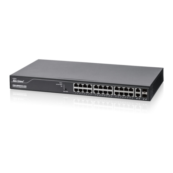
Introduction 1.1 Overview The PoE-GSH2624-370 is a 26-port Gigabit L2+ web smart PoE switch with 2-Port Gigabit TP/SFP slots and 24-Port Gigabit TP . This Switch can power on 802.3at/af cameras by RJ45 cable. Web-based management unit, associated with SNMP agent allow user access the switch remotely. -
Page 6: How To Use This Guide
1. Introduction 1.2 How to Use This Guide POE-GSH2624-370 is a SNMP and web smart PoE Switch with many functions. It is recommended that you read through the entire user’s guide whenever possible. The user guide is divided into different chapters. You should read at least go through the first 2 chapters before attempting to install the device. -
Page 7: Installing The Poe-Gsh2624-370
POE-GSH2624-370. For software configuration, please go to chapter 3 for more details. 2.1 Before You Start It is important to read through this section before you install the POE-GSH2624-370 The maximum cabling distance is 100 meters by Cat5e RJ45 cable. -
Page 8: Optional Accessory
2. Installing the POE-GSH2624-370 Compare the contents of your POE-GSH2624-370 package with the standard checklist above. If any item is missing or damaged, please contact your local dealer for service. 2.3 Optional Accessory The POE-GSH2624-370 has the following optional accessories which you can purchase from AirLive ... -
Page 9: Knowing Your Poe-Gsh2624-370
Make sure mounting surface on the bottom of the POE-GSH2624-370 is grease and dust free. Remove adhesive backing from your Rubber Feet. C. Apply the Rubber Feet to each corner on the bottom of the POE-GSH2624-370. These footpads can prevent the Switch from shock/vibration. AirLive POE-GSH2624-370 User Manual... - Page 10 Perform the following steps to rack mount the POE-GSH2624-370: Position one bracket to align with the holes on one side of the POE-GSH2624-370 and secure it with the smaller bracket screws. Then attach the remaining bracket to the other side of the POE-GSH2624-370.
-
Page 11: Led Table
2.5.3. Power On Connect the power cord to the power socket on the rear panel of the POE-GSH2624-370. The other side of power cord connects to the power outlet. The internal power supply of the POE-GSH2624-370 works with voltage range of AC in the 100-240VAC, frequency 50~60Hz. - Page 12 2. Installing the POE-GSH2624-370 Status Description System Green Power is ON Green On Link up 1000M Link/ACT/Speed Yellow On Link up 100M Blinking Data activating Green PoE device connecting AirLive POE-GSH2624-370 User Manual...
-
Page 13: Introduce The Poe-Gsh2624-370
The default password is airlive 3.2 Prepare your PC The POE-GSH2624-370 can be managed remotely by a PC through RJ-45 cable. The default IP address of the POE-GSH2624-370 is 192.168.2.1 with a subnet mask of 255.255.255.0. This means the IP address of the PC should be in the range of 192.168.2.2 to 192.168.2.253. -
Page 14: Introduction To Web Management
Web Management (HTTP): You can manage your POE-GSH2624-370 by simply typing its IP address in the web browser. Most functions of POE-GSH2624-370 can be accessed by web management inter face. We recommend using this interface for initial configurations. To begin, simply enter POE-GSH2624-370’s IP address (default is 192.168.2.1) on the web browser. - Page 15 Click “Enter” or ”Login”, then the home screen of the Web-based management appears. 3.4.2. Menu Structure of POE-GSH2624-370 The web management menu of POE-GSH2624-370 is divided into 3 parts: Top Bar, Side Menu Bar, and Main Screen. AirLive POE-GSH2624-370 User Manual...
- Page 16 3. Introduce the POE-GSH2624-370 Top Bar Side Menu Main Screen Top Bar: It display panel GUI. You can direct click the port on the Switch figure on the top of web page. Then, you will see the port information. On the left-top corner, there is a pull-down list for Auto Logout.
-
Page 17: Web Management: System Of Poe-Gsh2624-370
4.Web Management: System of POE-GSH2624-370 Web Management: System of POE-GSH2624-370 4.1 System This chapter describes the entire basic configuration tasks which includes the System Information and any manage of the Switch (e.g. Time, Account, IP, Syslog and NTP.) 4.1.1. System Information You can identify the system by configuring the contact information, name, and location of the switch. - Page 18 4.Web Management: System of POE-GSH2624-370 Parameter description: Model Name Model Name will show POE-GSH2624-370 by different models System Description Displays the system description. Location The system location configured in Configuration | System | Information | System Location. Contact The system contact configured in Configuration | System | Information | System Contact.
- Page 19 4.Web Management: System of POE-GSH2624-370 System Uptime The period of time the device has been operational. Bootloader Version Displays the current boot loader version number. Firmware Version The software version of this switch. Hardware-Mechanical Version The hardware and mechanical version of this switch.
- Page 20 0 to 128, and the allowed content is the ASCII characters from 32 to 126. 4.1.2. IP Advance This sector is to provide and config the IP information of the POE-GSH2624-370. 4.1.2.1. IP Configuration The IPv4 address for the switch could be obtained via DHCP Server for VLAN 1. To manually configure an address, you need to change the switch's default settings to values that are compatible with your network.
- Page 21 4.Web Management: System of POE-GSH2624-370 3. Click Add Route then you can create new Route on the switch 4. Click Apply Parameter description: IP Configuration Mode: Configure whether the IP stack should act as a Host or a Router. In Host mode, IP traffic between interfaces will not be routed.
- Page 22 4.Web Management: System of POE-GSH2624-370 • No DNS server No DNS server will be used. • Configured Explicitly provide the IP address of the DNS Server in dotted decimal notation. • From this DHCP interface Specify from which DHCP-enabled interface a provided DNS server should be preferred.
- Page 23 4.Web Management: System of POE-GSH2624-370 IPv4 Address The IPv4 address of the interface in dotted decimal notation. If DHCP is enabled, this field is not used. The field may also be left blank if IPv4 operation on the interface is not desired.
- Page 24 4.Web Management: System of POE-GSH2624-370 Gateway The IP address of the IP gateway. Valid format is dotted decimal notationor a valid IPv6 notation. Gateway and Network must be of the same type. Next Hop VLAN (Only for IPv6) The VLAN ID (VID) of the specific IPv6 interface associated with the gateway.
- Page 25 4.Web Management: System of POE-GSH2624-370 Parameter description: IP Interfaces Interface Show the name of the interface. Type Show the address type of the entry. This may be LINK or IPv4. Address Show the current address of the interface (of the given type).
- Page 26 4.Web Management: System of POE-GSH2624-370 Gateway Show the gateway address of this route. Status Show the status flags of the route. Neighbour cache IP Address Show the IP address of the entry. Link Address Show the Link (MAC) address for which a binding to the IP address given exist.
- Page 27 4.Web Management: System of POE-GSH2624-370 Parameter description: Time Configuration Clock Source: There are two modes for configuring how the Clock Source from. Select "Use Local Settings" : Clock Source from Local Time. Select "Use NTP Server" : Clock Source from NTP Server.
- Page 28 4.Web Management: System of POE-GSH2624-370 System Date: Show the current time of the system. The year of system date limits between 2011 and 2037. Time Zone Configuration Time Zone: Lists various Time Zones worldwide. Select appropriate Time Zone from the drop down and click Apply to set.
- Page 29 4.Web Management: System of POE-GSH2624-370 Month - Select the ending month. Hours - Select the ending hour. Minutes - Select the ending minute. Offset settings: Offset - Enter the number of minutes to add during Daylight Saving Time. ( Range:...
- Page 30 4.Web Management: System of POE-GSH2624-370 Parameter description: Mode : Indicates the NTP mode operation. Possible modes are: Enabled: Enable NTP client mode operation. Disabled: Disable NTP client mode operation. Server 1 to 5 : Provide the NTP IPv4 or IPv6 address of this switch. IPv6 address is in 128-bit records represented as eight fields of up to four hexadecimal digits with a colon separating each field (:).
- Page 31 4.Web Management: System of POE-GSH2624-370 4.1.4. Log The log is a standard for logging program messages . It allows separation of the software that generates messages from the system that stores them and the software that reports and analyzes them. It can be used as well a generalized informational, analysis and debugging messages.
- Page 32 4.Web Management: System of POE-GSH2624-370 Syslog Level : Indicates what kind of message will send to syslog server. Possible modes are: Info: Send information, warnings and errors. Warning: Send warnings and errors. Error: Send errors. Buttons These buttons are displayed on the NTP page: Apply –...
- Page 33 4.Web Management: System of POE-GSH2624-370 Parameter description: These parameters are displayed on the UPnP Configuration page: Mode : Indicates the UPnP operation mode. Possible modes are: Enabled: Enable UPnP mode operation. Disabled: Disable UPnP mode operation. When the mode is enabled, two ACEs are added automatically to trap UPNP related packets to CPU.
- Page 34 4.Web Management: System of POE-GSH2624-370 4.1.6.1. LLDP Configuration You can per port to do the LLDP configuration and the detail parameters, the settings will take effect immediately. This page allows the user to inspect and configure the current LLDP port settings.
- Page 35 4.Web Management: System of POE-GSH2624-370 Parameter description: LLDP Parameters Tx Interval : The switch periodically transmits LLDP frames to its neighbours for having the network discovery information up-to-date. The interval between each LLDP frame is determined by the Tx Interval value. Valid values are restricted to 5 - 32768 seconds.
- Page 36 4.Web Management: System of POE-GSH2624-370 Tx only The switch will drop LLDP information received from neighbors, but will send out LLDP information. Disabled The switch will not send out LLDP information, and will drop LLDP information received from neighbors. Enabled The switch will send out LLDP information, and will analyze LLDP information received from neighbors.
- Page 37 4.Web Management: System of POE-GSH2624-370 Port Descr : Optional TLV: When checked the "port description" is included in LLDP information transmitted. Sys Name : Optional TLV: When checked the "system name" is included in LLDP information transmitted. Sys Descr : Optional TLV: When checked the "system description"...
- Page 38 4.Web Management: System of POE-GSH2624-370 This page allows you to configure the LLDP-MED. This function applies to VoIP devices which support LLDP-MED. Web Interface To configure LLDP-MED: 1. Click LLDP-MED Configuration 2. Modify Fast start repeat count parameter, default is 4 3.
- Page 39 4.Web Management: System of POE-GSH2624-370 Parameter description: Fast start repeat count Rapid startup and Emergency Call Service Location Identification Discovery of endpoints is a critically important aspect of VoIP systems in general. In addition, it is best to advertise only those pieces of information which are specifically relevant to particular endpoint types...
- Page 40 4.Web Management: System of POE-GSH2624-370 It should be noted that LLDP-MED and the LLDP-MED Fast Start mechanism is only intended to run on links between LLDP-MED Network Connectivity Devices and Endpoint Devices, and as such does not apply to links between LAN infrastructure elements, including Network Connectivity Devices, or other types of links.
- Page 41 4.Web Management: System of POE-GSH2624-370 NAD83/MLLW: North American Datum 1983, CRS Code 4269, Prime Meridian Name: Greenwich; The associated vertical datum is Mean Lower Low Water (MLLW). This datum pair is to be used when referencing locations on water/sea/ocean. Civic Address Location IETF Geopriv Civic Address based Location Configuration Information (Civic Address LCI).
- Page 42 4.Web Management: System of POE-GSH2624-370 12. House no. suffix : House number suffix - Example: A, 1/2. 13. Landmark : Landmark or vanity address - Example: Columbia University. 14. Additional location info : Additional location info - Example: South Wing.
- Page 43 4.Web Management: System of POE-GSH2624-370 26. Emergency Call Service : Emergency Call Service ELIN identifier data format is defined to carry the ELIN identifier as used during emergency call setup to a traditional CAMA or ISDN trunk-based PSAP. This format consists of a numerical digit string, corresponding to the ELIN to be used for emergency calling.
- Page 44 4.Web Management: System of POE-GSH2624-370 It should be noted that LLDP-MED is not intended to run on links other than between Network Connectivity Devices and Endpoints, and therefore does not need to advertise the multitude of network policies that frequently run on an aggregated link interior to the LAN.
- Page 45 4.Web Management: System of POE-GSH2624-370 7. Streaming Video - for use by broadcast or multicast based video content distribution and other similar applications supporting streaming video services that require specific network policy treatment. Video applications relying on TCP with buffering would not be an intended use of this application type.
- Page 46 4.Web Management: System of POE-GSH2624-370 Port Policies Configuration : Every port may advertise a unique set of network policies or different attributes for the same network policies, based on the authenticated user identity or port configuration. 10. Port : The port number to which the configuration applies.
- Page 47 4.Web Management: System of POE-GSH2624-370 Parameter description: Local Port : The port on which the LLDP frame was received. Chassis ID : The Chassis ID is the identification of the neighbour's LLDP frames. Port ID : The Remote Port ID is the identification of the neighbour port.
- Page 48 4.Web Management: System of POE-GSH2624-370 Buttons Auto-refresh: Check this box to refresh the page automatically. Automatic refresh occurs every 3 seconds. Refresh: Click to refresh the page. 4.1.6.4. LLDP-MED Neighbor This page provides a status overview of all LLDP-MED neighbors. The displayed table contains a row for each port on which an LLDP neighbor is detected.
- Page 49 4.Web Management: System of POE-GSH2624-370 LLDP-MED Network Connectivity Device Definition LLDP-MED Network Connectivity Devices, as defined in TIA-1057, provide access to the IEEE 802 based LAN infrastructure for LLDP-MED Endpoint Devices. An LLDP-MED Network Connectivity Device is a LAN access device based on any of the following technologies: 1.
- Page 50 4.Web Management: System of POE-GSH2624-370 LLDP-MED Media Endpoint (Class II) : The LLDP-MED Media Endpoint (Class II) definition is applicable to all endpoint products that have IP media capabilities however may or may not be associated with a particular end user. Capabilities include all of the capabilities defined for the previous Generic Endpoint Class (Class I), and are extended to include aspects related to media streaming.
- Page 51 4.Web Management: System of POE-GSH2624-370 Application Type : Application Type indicating the primary function of the application(s) defined for this network policy, advertised by an Endpoint or Network Connectivity Device. The possible application types are shown below. 1. Voice - for use by dedicated IP Telephony handsets and other similar appliances supporting interactive voice services.
- Page 52 4.Web Management: System of POE-GSH2624-370 Untagged: The device is using an untagged frame format and as such does not include a tag header as defined by IEEE 802.1Q-2003. Tagged: The device is using the IEEE 802.1Q tagged frame format. VLAN ID : VLAN ID is the VLAN identifier (VID) for the port as defined in IEEE 802.1Q-2003.
- Page 53 4.Web Management: System of POE-GSH2624-370 4.1.6.5. LLDP Neighbor PoE This page allows the user to inspect the current status for all PoE ports. The section show all port Power Over Ethernet Status if the PD side use the LLDP to do the PoE handsharking.
- Page 54 4.Web Management: System of POE-GSH2624-370 Power Priority : Power Power Priority represents the priority of the PD device, or the power priority associated with the PSE type device's port that is sourcing the power. There are three levels of power priority. The three levels are: Critical, High and Low.
- Page 55 4.Web Management: System of POE-GSH2624-370 4.1.6.6. LLDP Neighbor EEE By using EEE power savings can be achieved at the expense of traffic latency. This latency occurs due to that the circuits EEE turn off to save power, need time to boot up before sending traffic over the link.
- Page 56 4.Web Management: System of POE-GSH2624-370 Fallback Receive Tw : The link partner’s fallback receive Tw. A receiving link partner may inform the transmitter of an alternate desired Tw_sys_tx. Since a receiving link partner is likely to have discrete levels for savings, this provides the transmitter with additional information that it may use for a more efficient allocation.
- Page 57 4.Web Management: System of POE-GSH2624-370 10. Buttons Auto-refresh: Check this box to refresh the page automatically. Automatic refresh occurs every 3 seconds. Refresh: Click to refresh the page. 4.1.6.7. LLDP Statistics Two types of counters are shown. Global counters are counters that refer to the whole...
- Page 58 4.Web Management: System of POE-GSH2624-370 Parameter description: Global Counters Neighbor entries were last changed at : It also shows the time when the last entry was last deleted or added. It also shows the time elapsed since the last change was detected.
-
Page 59: Port Management
4.Web Management: System of POE-GSH2624-370 Frames Discarded : If an LLDP frame is received on a port, and the switch's internal table has run full, the LLDP frame is counted and discarded. This situation is known as "Too Many Neighbours" in the LLDP standard. LLDP frames require a new entry in the table when the Chassis ID or Remote Port ID is not already contained within the table. - Page 60 4.Web Management: System of POE-GSH2624-370 4.2.1.1. Ports This page displays current port configurations. Ports can also be configured here. Web Interface To configure a Current Port Configuration in the web interface: 1. Click Configuration, Ports Configuration, and Ports 2. Specify the Speed Configured, Flow Control, Maximum Frame size, Excessive Collision mode and Power Control.
- Page 61 4.Web Management: System of POE-GSH2624-370 Link : The current link state is displayed graphically. Green indicates the link is up and red that it is down. Current Link Speed : Provides the current link speed of the port. Configured Link Speed : Selects any available link speed for the given switch port.
- Page 62 4.Web Management: System of POE-GSH2624-370 frames on the port are obeyed, and the Current Tx column indicates whether pause frames on the port are transmitted. The Rx and Tx settings are determined by the result of the last Auto-Negotiation. Check the configured column to use flow control. This setting is related to the setting for Configured Link Speed.
- Page 63 4.Web Management: System of POE-GSH2624-370 Parameter description: Port : This is the logical port number for this row. Description : Enter up to 47 characters to be descriptive name for identifies this port. Buttons Apply – Click to save changes.
- Page 64 4.Web Management: System of POE-GSH2624-370 Web Interface To Display the Port Statistics Overview in the web interface: Click Monitor, Port, then Traffic Overview If you want to auto-refresh then you need to evoke the “Auto-refresh”. Click “ Refresh“ to refresh the port statistics or clear all information when you click “...
- Page 65 4.Web Management: System of POE-GSH2624-370 Buttons Auto-refresh: Check this box to refresh the page automatically. Automatic refresh occurs every 3 seconds. Refresh: Click to refresh the page. Clear: Clears the counters for all ports. 4.2.2.2. Detail Statistics The section describes how to provide detailed traffic statistics for a specific switch port. Use the port select box to select which switch port details to display.
- Page 66 4.Web Management: System of POE-GSH2624-370 Parameter description: Auto-refresh: To evoke the auto-refresh to refresh the Port Statistics information automatically. AirLive POE-GSH2624-370 User Manual...
- Page 67 4.Web Management: System of POE-GSH2624-370 Upper left scroll bar: To scroll which port to display the Port statistics with “Port-0”, “Port-1... Receive Total and Transmit Total Rx and Tx Packets : The number of received and transmitted (good and bad) packets.
- Page 68 4.Web Management: System of POE-GSH2624-370 Rx Oversize : The number of long 2 frames received with valid CRC. Rx Fragments : The number of short 1 frames received with invalid CRC. Rx Jabber : The number of long 2 frames received with invalid CRC.
- Page 69 4.Web Management: System of POE-GSH2624-370 4.2.3. SFP Port Info The section describes that switch could display the SFP module detail information which you connect it to the switch. The information includes: Connector type, Fiber type, wavelength, baud rate and Vendor OUI etc.
- Page 70 4.Web Management: System of POE-GSH2624-370 Vendor OUI: Display the Manufacturer's OUI code which is assigned by IEEE. Vendor Name: Display the company name of the module manufacturer. Vendor P/N: Display the product name of the naming by module manufacturer. Vendor Revision: Display the module revision.
- Page 71 4.Web Management: System of POE-GSH2624-370 For ports that are not EEE-capable the corresponding EEE checkboxes are grayed out and thus impossible to enable EEE for. When a port is powered down for saving power, outgoing traffic is stored in a buffer until the port is powered up again.
- Page 72 4.Web Management: System of POE-GSH2624-370 Parameter description: Optimize EEE for The switch can be set to optimize EEE for either best power saving or least traffic latency. Port: The switch port number of the logical port. ActiPHY : Link down power savings enabled.
- Page 73 4.Web Management: System of POE-GSH2624-370 4.2.4.2. Status This page provides the current status for EEE. Web Interface To display the power Saving in the web interface: Click Monitor, Port Power Savings. Figure 4.2.4.2: The Ports States Parameter description: Local Port This is the logical port number for this row.
- Page 74 4.Web Management: System of POE-GSH2624-370 Actiphy Savings Shows if the system is currently saving power due to ActiPhy. PerfectReach Savings Shows if the system is currently saving power due to PerfectReach. Link Aggregation The Aggregation is used to configure the settings of Link Aggregation. You can bundle more than one port with the same speed, full duplex and the same MAC to be a single logical port, thus the logical port aggregates the bandwidth of these ports.
- Page 75 4.Web Management: System of POE-GSH2624-370 Parameter description: Hash Code Contributors Source MAC Address : The Source MAC address can be used to calculate the destination port for the frame. Check to enable the use of the Source MAC address, or uncheck to disable.
- Page 76 4.Web Management: System of POE-GSH2624-370 TCP/UDP Port Number : The TCP/UDP port number can be used to calculate the destination port for the frame. Check to enable the use of the TCP/UDP Port Number, or uncheck to disable. By default, TCP/UDP Port Number is enabled.
- Page 77 4.Web Management: System of POE-GSH2624-370 Parameter description: Port : The switch port number. LACP Enabled Controls whether LACP is enabled on this switch port. LACP will form an aggregation when 2 or more ports are connected to the same partner.
- Page 78 4.Web Management: System of POE-GSH2624-370 Timeout The Timeout controls the period between BPDU transmissions. Fast will transmit LACP packets each second, while Slow will wait for 30 seconds before sending a LACP packet. Prio The Prio controls the priority of the port. If the LACP partner wants to form a larger group than is supported by this device then this parameter will control which ports will be active and which ports will be in a backup role.
- Page 79 4.Web Management: System of POE-GSH2624-370 Partner System ID : The system ID (MAC address) of the aggregation partner. Partner Key : The Key that the partner has assigned to this aggregation ID. Last changed : The time since this aggregation changed.
- Page 80 4.Web Management: System of POE-GSH2624-370 Parameter description: Port : The switch port number. LACP : 'Yes' means that LACP is enabled and the port link is up. 'No' means that LACP is not enabled or that the port link is down. 'Backup' means that the port could not join the aggregation group but will join if other port leaves.
- Page 81 4.Web Management: System of POE-GSH2624-370 4.2.5. Loop Protection The loop Protection is used to detect the presence of traffic. When switch receives packet’s (looping detection frame) MAC address the same as oneself from port, show Loop Protection happens. The port will be locked when it received the looping Proection frames.
-
Page 82: Poe Management
Auto-refresh: Check this box to enable an automatic refresh of the page at regular intervals. 4.3 PoE Management PoE-GSH2624-370 support 802.3at/af Power-Over-Ethernet (PoE). Each port can provide up to 30W power with Data on RJ45 cable. The PoE detect function is follow the table... - Page 83 4.Web Management: System of POE-GSH2624-370 Power levels available Power range Class Usage Class description [Watt] Default 15.4 Classification unimplemented Optional Very Low power Optional Low power Optional 15.4 Mid power Valid for 802.3at (Type 2) devices, not allowed High power for 802.3af devices...
- Page 84 4.Web Management: System of POE-GSH2624-370 Parameter description: Power Supply Configuration Reserved Power determined by : There are three modes for configuring how the ports/PDs may reserve power. 1. Allocated mode: In this mode the user allocates the amount of power that each port may reserve.
- Page 85 4.Web Management: System of POE-GSH2624-370 PoE Mode : The PoE Mode represents the PoE operating mode for the port. Disabled: PoE disabled for the port. PoE : Enables PoE IEEE 802.3af (Class 4 PDs limited to 15.4W) PoE+ : Enables PoE+ IEEE 802.3at (Class 4 PDs limited to 30W) Priority : The Priority represents the ports priority.
- Page 86 4.Web Management: System of POE-GSH2624-370 PD Class Each PD is classified according to a class that defines the maximum power the PD will use. The PD Class shows the PDs class. Five Classes are defined: Class 0: Max. power 15.4 W Class 1: Max.
- Page 87 4.Web Management: System of POE-GSH2624-370 Buttons Auto-refresh: Check this box to refresh the page automatically. Automatic refresh occurs every 3 seconds. Refresh: Click to refresh the page. 4.3.3. PoE Power Delay This page allows the user to setting the delay time of power providing after device rebooted.
- Page 88 4.Web Management: System of POE-GSH2624-370 Delay Mode : Turn on / off the power delay function. Enabled: Enable POE Power Delay. Disabled: Disable POE Power Delay. Delay Time(0~300sec) : When rebooting, the PoE port will start to provide power to the PD when it out of delay time.
- Page 89 4.Web Management: System of POE-GSH2624-370 Parameter description: Power Supply Configuration Port : This is the logical port number for this row. Status : PoE Scheduling Status. Enabled: Enable POE Scheduling. Disabled: Disable POE Scheduling. Hour : The time of PoE port provide power of a day.
- Page 90 4.Web Management: System of POE-GSH2624-370 Parameter description: Power Supply Configuration Ping Check : Enable Ping Check function can detects the connection between PoE port and power device. Disable will turn off the detection. Port : This is the logical port number for this row.
-
Page 91: Vlan Management
4.Web Management: System of POE-GSH2624-370 4.4 VLAN Management To assign a specific VLAN for management purpose. The management VLAN is used to establish an IP connection to the switch from a workstation connected to a port in the VLAN. This connection supports a VSM, SNMP, and Telnet session. By default, the active management VLAN is VLAN 1, but you can designate any VLAN as the management VLAN using the Management VLAN window. - Page 92 4.Web Management: System of POE-GSH2624-370 Parameter description: Global VLAN Configuration Existing VLANs : This field shows the VLANs that are created on the switch. By default, only VLAN 1 exists. More VLANs may be created by using a list syntax where the individual elements are separated by commas. Ranges are specified with a dash separating the lower and upper bound.
- Page 93 4.Web Management: System of POE-GSH2624-370 Trunk: Trunk ports can carry traffic on multiple VLANs simultaneously, and are normally used to connect to other switches. Trunk ports have the following characteristics: • By default, a trunk port is member of all existing VLANs.
- Page 94 4.Web Management: System of POE-GSH2624-370 Unaware: On ingress, all frames, whether carrying a VLAN tag or not, get classified to the Port VLAN, and possible tags are not removed on egress. C-Port: On ingress, frames with a VLAN tag with TPID = 0x8100 get classified to the VLAN ID embedded in the tag.
- Page 95 4.Web Management: System of POE-GSH2624-370 Ingress Acceptance : Hybrid ports allow for changing the type of frames that are accepted on ingress. Tagged and Untagged Both tagged and untagged frames are accepted. Tagged Only Only tagged frames are accepted on ingress. Untagged frames are discarded.
- Page 96 4.Web Management: System of POE-GSH2624-370 10. Forbidden VLANs : A port may be configured to never be member of one or more VLANs. This is particularly useful when dynamic VLAN protocols like MVRP and GVRP must be prevented from dynamically adding ports to VLANs.
- Page 97 4.Web Management: System of POE-GSH2624-370 MVRP : Multiple VLAN Registration Protocol (MVRP) allows dynamic registration and deregistration of VLANs on ports on a VLAN bridged network. Voice VLAN : Voice VLAN is a VLAN configured specially for voice traffic typically originating from IP phones.
- Page 98 4.Web Management: System of POE-GSH2624-370 Buttons Auto-refresh: Check this box to refresh the page automatically. Automatic refresh occurs every 3 seconds. Refresh: Click to refresh the page. 4.4.3. VLAN Port Status The function Port Status gathers the information of all VLAN status and reports it by the order of Static NAS MVRP MVP Voice VLAN MSTP GVRP Combined.
- Page 99 4.Web Management: System of POE-GSH2624-370 NAS : NAS provides port-based authentication, which involves communications between a Supplicant, Authenticator, and an Authentication Server. Voice VLAN : Voice VLAN is a VLAN configured specially for voice traffic typically originating from IP phones.
- Page 100 4.Web Management: System of POE-GSH2624-370 Tx Tag : Shows egress filtering frame status whether tagged or untagged. UVID : Shows UVID (untagged VLAN ID). Port's UVID determines the packet's behaviour at the egress side. Conflicts : Shows status of Conflicts whether exists or not. When a Volatile VLAN User...
- Page 101 4.Web Management: System of POE-GSH2624-370 MAC-based VLANs group VLAN members by MAC address. With MAC-based VLAN configured, the device adds a VLAN tag to an untagged frame according to its source MAC address. MAC-based VLANs are mostly used in conjunction with security technologies such as 802.1X to provide secure, flexible network access for terminal devices.
- Page 102 4.Web Management: System of POE-GSH2624-370 Adding a New MAC-based VLAN Click to add a new MAC-based VLAN entry. An empty row is added to the table, and the MAC-based VLAN entry can be configured as needed. Any unicast MAC address can be configured for the MAC-based VLAN entry. No broadcast or multicast MAC addresses are allowed.
- Page 103 4.Web Management: System of POE-GSH2624-370 4.4.6. Protocol to Group This page allows you to add new protocols to Group Name (unique for each Group) mapping entries as well as allow you to see and delete already mapped entries for the selected stack switch unit switch.
- Page 104 4.Web Management: System of POE-GSH2624-370 1. For Ethernet: Values in the text field when Ethernet is selected as a Frame Type is called etype. Valid values for etype ranges from 0x0600-0xffff 2. For LLC: Valid value in this case is comprised of two different sub-values.
- Page 105 4.Web Management: System of POE-GSH2624-370 4.4.7. Group to VLAN This section allows you to map a already configured Group Name to a VLAN for the selected stack switch unit switch . Web Interface To Display Group Name to VLAN mapping table configured in the web interface: Click Group Name VLAN configuration and add new entry.
- Page 106 4.Web Management: System of POE-GSH2624-370 Adding a New Group to VLAN mapping entry : Click to add a new entry in mapping table. An empty row is added to the table, the Group Name, VLAN ID and port members can be configured as needed. Legal values for a VLAN ID are 1 through 4095.
- Page 107 4.Web Management: System of POE-GSH2624-370 Parameter description: Delete To delete a IP subnet-based VLAN entry, check this box and press save. The entry will be deleted on the selected switch in the stack. VCE ID Indicates the index of the entry. It is user configurable. It's value ranges from 0-128.
- Page 108 4.Web Management: System of POE-GSH2624-370 Web Interface To configure VLAN membership configuration in the web interface: Click VLAN membership Configuration. Specify Management VLAN ID. 0~ 4094 Click Apply. Parameter description: Delete : To delete a private VLAN entry, check this box. The entry will be deleted during the next save.
- Page 109 4.Web Management: System of POE-GSH2624-370 Buttons: Apply – Click to save changes. Reset- Click to undo any changes made locally and revert to previously saved values. 4.4.9. Port Isolation Port Isolation provides for an apparatus and method to isolate ports on layer 2 switches on the same VLAN to restrict traffic flow.
- Page 110 4.Web Management: System of POE-GSH2624-370 Parameter description: Port Members : A check box is provided for each port of a private VLAN. When checked, port isolation is enabled on that port. When unchecked, port isolation is disabled on that port. By default, port isolation is disabled on all ports.
- Page 111 4.Web Management: System of POE-GSH2624-370 Parameter description: Mode : Indicates the Voice VLAN mode operation. We must disable MSTP feature before we enable Voice VLAN. It can avoid the conflict of ingress filtering. Possible modes are: Enabled: Enable Voice VLAN mode operation.
- Page 112 4.Web Management: System of POE-GSH2624-370 Port Security : Indicates the Voice VLAN port security mode. When the function is enabled, all non-telephonic MAC addresses in the Voice VLAN will be blocked for 10 seconds. Possible port modes are: Enabled: Enable Voice VLAN security mode operation.
-
Page 113: Quality Of Service
4.Web Management: System of POE-GSH2624-370 Parameter description: Delete : Check to delete the entry. It will be deleted during the next save. Telephony OUI : A telephony OUI address is a globally unique identifier assigned to a vendor by IEEE. It must be 6 characters long and the input format is "xx-xx-xx" (x is a hexadecimal digit). - Page 114 4.Web Management: System of POE-GSH2624-370 The switch support advanced memory control mechanisms providing excellent performance of all QoS classes under any traffic scenario, including jumbo frame. A super priority queue with dedicated memory and strict highest priority in the arbitration. The ingress super priority queue allows traffic recognized as CPU traffic to be received and queued for transmission to the CPU even when all the QoS class queues are congested.
- Page 115 4.Web Management: System of POE-GSH2624-370 All frames are classified to a CoS. There is a one to one mapping between CoS, queue and priority. A CoS of 0 (zero) has the lowest priority. If the port is VLAN aware, the frame is tagged and Tag Class. is enabled, then the frame is classified to a CoS that is mapped from the PCP and DEI value in the tag.
- Page 116 4.Web Management: System of POE-GSH2624-370 NOTE: This setting has no effect if the port is VLAN unaware. Tagged frames received on VLAN unaware ports are always classified to the default CoS and DPL. DSCP Based : Click to Enable DSCP Based QoS Ingress Port Classification.
- Page 117 4.Web Management: System of POE-GSH2624-370 Parameter description: Port : The logical port for the settings contained in the same row. Click on the port number in order to configure the schedulers. Enabled : To evoke which Port you need to enable the QoS Ingress Port Policers function.
- Page 118 4.Web Management: System of POE-GSH2624-370 4.5.3. Port Shapers This section provides an overview of QoS Egress Port Shapers for all switch ports. Others the user could get all detail information ot the ports belong to the currently selected stack unit, as reflected by the page header.
- Page 119 4.Web Management: System of POE-GSH2624-370 If you select the scheduler mode with weighted then the screen will change as the figure. Parameter description: Port : The logical port for the settings contained in the same row. Click on the port number in order to configure the shapers.
- Page 120 4.Web Management: System of POE-GSH2624-370 Shapers (Qn) : Shows "disabled" or actual queue shaper rate - e.g. "800 Mbps". Scheduler Mode : Controls whether the scheduler mode is "Strict Priority" or "Weighted" on this switch port. Queue Shaper Enable : Controls whether the queue shaper is enabled for this queue on this switch port.
- Page 121 4.Web Management: System of POE-GSH2624-370 14. . Buttons: Apply – Click to save changes. Reset- Click to undo any changes made locally and revert to previously saved values. 4.5.4. Storm Control The section allows user to configure the Storm control for the switch. There is a unicast storm rate control, multicast storm rate control, and a broadcast storm rate control.
- Page 122 4.Web Management: System of POE-GSH2624-370 Parameter description: Frame Type : The settings in a particular row apply to the frame type listed here: Unicast, Multicast or Broadcast. Enable : Enable or disable the storm control status for the given frame type.
- Page 123 4.Web Management: System of POE-GSH2624-370 Click the Port index to set the QoS Egress Port Schedulers If you select the scheduler mode with wighted then the screen will change as the figure. AirLive POE-GSH2624-370 User Manual...
- Page 124 4.Web Management: System of POE-GSH2624-370 Parameter description: Port : The logical port for the settings contained in the same row. Click on the port number in order to configure the schedulers. Mode : Shows the scheduling mode for this port.
- Page 125 4.Web Management: System of POE-GSH2624-370 Queue Shaper Unit : Controls the unit of measure for the queue shaper rate as "kbps" or "Mbps". The default value is "kbps". Queue Shaper Excess : Controls whether the queue is allowed to use excess bandwidth.
- Page 126 4.Web Management: System of POE-GSH2624-370 Click the Port index to set the QoS Port Tag Remarking AirLive POE-GSH2624-370 User Manual...
- Page 127 4.Web Management: System of POE-GSH2624-370 Parameter description: Mode : Controls the tag remarking mode for this port. Classified: Use classified PCP/DEI values. Default: Use default PCP/DEI values. Mapped: Use mapped versions of QoS class and DP level. PCP/DEI Configuration : Controls the default PCP and DEI values used when the mode is set to Default.
- Page 128 4.Web Management: System of POE-GSH2624-370 (QoS class, DP level) to (PCP, DEI) Mapping : Controls the mapping of the classified (QoS class, DP level) to (PCP, DEI) values when the mode is set to Mapped. Buttons: Apply – Click to save changes.
- Page 129 4.Web Management: System of POE-GSH2624-370 Parameter description: Port : The Port column shows the list of ports for which you can configure DSCP ingress and egress settings. Ingress : In Ingress settings you can change ingress translation and classification settings for individual ports.
- Page 130 4.Web Management: System of POE-GSH2624-370 4.5.7.2. DSCP Translation The section describes the swtich allows you to configure the basic QoS DSCP Translation settings for all switches. DSCP translation can be done in Ingress or Egress. Web Interface To configure the DSCP Translation parameters in the web interface: 1.
- Page 131 4.Web Management: System of POE-GSH2624-370 Ingress : Ingress side DSCP can be first translated to new DSCP before using the DSCP for QoS class and DPL map. There are two configuration parameters for DSCP Translation – Translate : DSCP at Ingress side can be translated to any of (0-63) DSCP values.
- Page 132 4.Web Management: System of POE-GSH2624-370 1.Click Configuration, QoS, DSCP Translation 2. Scroll to set the DSCP Parameters 3. Click the save to save the setting 4. If you want to cancel the setting then you need to click the Reset button.
- Page 133 4.Web Management: System of POE-GSH2624-370 Auto-refresh : To evoke the auto-refresh icon then the device will refresh the information automatically. Upper right icon (Refresh): You can click them for refresh the DSCP Classification information by manual. 4.5.7.4. DSCP-Based QoS The section will teach user to configure the DSCP-Based QoS mode that This page allows you to configure the basic QoS DSCP based QoS Ingress Classification settings for all switches.
- Page 134 4.Web Management: System of POE-GSH2624-370 Parameter description: DSCP : Maximum number of support ed DSCP values are 64. Trust : Click to check if the DSCP value is trusted. QoS Class : QoS Class value can be any of (0-7)
- Page 135 4.Web Management: System of POE-GSH2624-370 4.5.8.1. Configuration Web Interface To configure the QoS Control List parameters in the web interface: 1. Click Configuration, QoS, QoS Contol List 2. Click the to add a new QoS Control List 3. Scroll all parameters and evoke the Port Member to join the QCE rules 4.
- Page 136 4.Web Management: System of POE-GSH2624-370 Parameter description: QCE# : Indicates the index of QCE. Port : Indicates the list of ports configured with the QCE. DMAC : Indicates the destination MAC address. Possible values are: Any: Match any DMAC. Unicast: Match unicast DMAC.
- Page 137 4.Web Management: System of POE-GSH2624-370 PCP : Priority Code Point: Valid values of PCP are specific(0, 1, 2, 3, 4, 5, 6, 7) or range(0-1, 2-3, 4-5, 6-7, 0-3, 4-7) or 'Any'. DEI : Drop Eligible Indicator: Valid value of DEI are 0, 1 or 'Any'.
- Page 138 4.Web Management: System of POE-GSH2624-370 : Inserts a new QCE before the current row. Edits the QCE. : Moves the QCE up the list. : Moves the QCE down the list. : Deletes the QCE. : The lowest plus sign adds a new entry at the bottom of the QCE listings.
- Page 139 4.Web Management: System of POE-GSH2624-370 NOTE: All frame types are explained below: 1. Any : Allow all types of frames. 2. Ethernet : Ethernet Type Valid ethernet type can have value within 0x600-0xFFFF or 'Any', default value is 'Any'. 3. LLC: SSAP Address Valid SSAP(Source Service Access...
- Page 140 4.Web Management: System of POE-GSH2624-370 14. Action Configuration : Class QoS Class: "class (0-7)", default- basic classification DP Valid DP Level can be (0-3)", default- basic classification DSCP Valid dscp value can be (0-63, BE, CS1-CS7, EF or AF11-AF43) 15. Buttons: Apply –...
- Page 141 4.Web Management: System of POE-GSH2624-370 User : Indicates the QCL user. QCE# Indicates the index of QCE. Frame Type : Indicates the type of frame to look for incomming frames. Possible frame types are: Any: The QCE will match all frame type.
- Page 142 4.Web Management: System of POE-GSH2624-370 Buttons Auto-refresh: Check this box to refresh the page automatically. Automatic refresh occurs every 3 seconds. Resolve Conflict: Click to release the resources required to add QCL entry, incase conflict status for any QCL entry is 'yes'.
-
Page 143: Spanning Tree
4.Web Management: System of POE-GSH2624-370 Parameter description: Port : The logical port for the settings contained in the same row. Qn : Qn is the Queue number, There are 8 QoS queues per port. Q0 is the lowest priority queue. - Page 144 4.Web Management: System of POE-GSH2624-370 Once a stable network topology has been established, all bridges listen for Hello BPDUs (Bridge Protocol Data Units) transmitted from the Root Bridge. If a bridge does not get a Hello BPDU after a predefined interval (Maximum Age), the bridge assumes that the link to the Root Bridge is down.
- Page 145 4.Web Management: System of POE-GSH2624-370 Parameter description: Basic Settings Protocol Version : The STP protocol version setting. Valid values are STP, RSTP and MSTP. Bridge Priority : Controls the bridge priority. Lower numeric values have better priority. The bridge priority plus the MSTI instance number, concatenated with the 6-byte MAC address of the switch forms a Bridge Identifier.
- Page 146 4.Web Management: System of POE-GSH2624-370 Max Age : The maximum age of the information transmitted by the Bridge when it is the Root Bridge. Valid values are in the range 6 to 40 seconds, and MaxAge must be <= (FwdDelay-1)*2.
- Page 147 4.Web Management: System of POE-GSH2624-370 4.6.2. MSTI Configuration When you implement an Spanning Tree protocol on the switch that the bridge instance. The CIST is not available for explicit mapping, as it will receive the VLANs not explicitly mapped. Due to the reason that you need to set the list of VLANs mapped to the MSTI. The VLANs must be separated with comma and/or space.
- Page 148 4.Web Management: System of POE-GSH2624-370 Parameter description: Configuration Identification Configuration Name : The name identifying the VLAN to MSTI mapping. Bridges must share the name and revision (see below), as well as the VLAN-to-MSTI mapping configuration in order to share spanning trees for MSTI's (Intra-region). The name is at most 32 characters.
- Page 149 4.Web Management: System of POE-GSH2624-370 4.6.2.1. MSTI Mapping When you implement an Spanning Tree protocol on the switch that the bridge instance. The CIST is not available for explicit mapping, as it will receive the VLANs not explicitly mapped. Due to the reason that you need to set the list of VLANs mapped to the MSTI. The VLANs must be separated with comma and/or space.
- Page 150 4.Web Management: System of POE-GSH2624-370 Parameter description: Configuration Identification Configuration Name : The name identifying the VLAN to MSTI mapping. Bridges must share the name and revision (see below), as well as the VLAN-to-MSTI mapping configuration in order to share spanning trees for MSTI's (Intra-region). The name is at most 32 characters.
- Page 151 4.Web Management: System of POE-GSH2624-370 4.6.2.2. MSTI Priorities When you implement a Spanning Tree protocol on the switch that the bridge instance. The CIST is the default instance which is always active. For controls the bridge priority. Lower numeric values have better priority. The bridge priority plus the MSTI instance number,...
- Page 152 4.Web Management: System of POE-GSH2624-370 Buttons Apply – Click to save changes. Reset- Click to undo any changes made locally and revert to previously saved values. 4.6.2.3. CIST Port When you implement an Spanning Tree protocol on the switch that the bridge instance. You need to configure the CIST Ports.
- Page 153 4.Web Management: System of POE-GSH2624-370 Parameter description: Port : The switch port number of the logical STP port. STP Enabled : Controls whether STP is enabled on this switch port. Path Cost : Controls the path cost incurred by the port. The Auto setting will set the path cost as appropriate by the physical link speed, using the 802.1D recommended values.
- Page 154 4.Web Management: System of POE-GSH2624-370 to prevent bridges external to a core region of the network influence the spanning tree active topology, possibly because those bridges are not under the full control of the administrator. This feature is also known as Root Guard.
- Page 155 4.Web Management: System of POE-GSH2624-370 Web Interface To configure the Spanning Tree MSTI Port Configuration parameters in the web interface: 1. Click Configuration, Spanning Tree, MSTI Ports 2. Scroll to select the MST1 or other MSTI Port 3. Click Get to set the detail parameters of the MSTI Ports.
- Page 156 4.Web Management: System of POE-GSH2624-370 Parameter description: Port : The switch port number of the corresponding STP CIST (and MSTI) port. Path Cost : Controls the path cost incurred by the port. The Auto setting will set the path cost as appropriate by the physical link speed, using the 802.1D recommended values.
- Page 157 4.Web Management: System of POE-GSH2624-370 Parameter description: MSTI : The Bridge Instance. This is also a link to the STP Detailed Bridge Status. Bridge ID : The Bridge ID of this Bridge instance. Root ID : The Bridge ID of the currently elected root bridge.
- Page 158 4.Web Management: System of POE-GSH2624-370 4.6.3.2. Port Status After you complete the STP configuration the you could to ask the switch display the STP Port Status. The Section provides you to ask switch to display the STP CIST port status for physical ports of the currently selected switch.:...
- Page 159 4.Web Management: System of POE-GSH2624-370 4.6.4. Port Statistics After you complete the STP configuration then you could to let the switch display the STP Statistics. The Section provides you to ask switch to display the STP Statistics detail counters of bridge ports in the currently selected switch.
-
Page 160: Mac Address Tables
4.Web Management: System of POE-GSH2624-370 Discarded Illegal : The number of illegal Spanning Tree BPDU's received (and discarded) on the port. Buttons Auto-refresh: Check this box to refresh the page automatically. Automatic refresh occurs every 3 seconds. Clear: Clears the counters for the selected port. - Page 161 4.Web Management: System of POE-GSH2624-370 MAC Table Learning Click configuration . Specify the Port Members(Auto,Disable,Secure). Click Apply. Static MAC Table Configuration Click configuration and Add new Static entry . Specify the VLAN IP and Mac address ,Port Members. Click Apply.
- Page 162 4.Web Management: System of POE-GSH2624-370 MAC Table Learning If the learning mode for a given port is greyed out, another module is in control of the mode, so that it cannot be changed by the user. An example of such a module is the MAC-Based Authentication under 802.1X.
- Page 163 4.Web Management: System of POE-GSH2624-370 Adding a New Static Entry : Click to add a new entry to the static MAC table. Specify the VLAN ID, MAC address, and port members for the new entry. Click "Apply". Buttons: Apply – Click to save changes.
- Page 164 4.Web Management: System of POE-GSH2624-370 The "Start from MAC address" and "VLAN" input fields allow the user to select the starting point in the MAC Table. Clicking the “Refresh” button will update the displayed table starting from that or the closest next MAC Table match. In addition, the two input fields will - upon a “Refresh”...
-
Page 165: Multicast
4.Web Management: System of POE-GSH2624-370 4.8 Multicast ICMP is an acronym for Internet Control Message Protocol. It is a protocol that generated the error response, diagnostic or routing purposes. ICMP messages generally contain information about routing difficulties or simple exchanges such as time-stamp or echo transactions. - Page 166 4.Web Management: System of POE-GSH2624-370 6. If you want to cancel the setting then you need to click the Reset button. It will revert to previously saved values Parameter description: Snooping Enabled: Enable the Global IGMP Snooping. Unregistered IPMCv4 Flooding enabled : Enable unregistered IPMCv4 traffic flooding.
- Page 167 4.Web Management: System of POE-GSH2624-370 Proxy Enabled : Enable IGMP Proxy. This feature can be used to avoid forwarding unnecessary join and leave messages to the router side. Port : It shows the physical Port index of switch. Router Port : Specify which ports act as router ports.
- Page 168 4.Web Management: System of POE-GSH2624-370 Parameter description: Delete : Check to delete the entry. The designated entry will be deleted during the next save. VLAN ID : It displays the VLAN ID of the entry. IGMP Snooping Enabled : Enable the per-VLAN IGMP Snooping. Only up to 32 VLANs can be selected. .
- Page 169 4.Web Management: System of POE-GSH2624-370 Compatibility : Compatibility is maintained by hosts and routers taking appropriate actions depending on the versions of IGMP operating on hosts and routers within a network. The allowed selection is IGMP-Auto, Forced IGMPv1, Forced IGMPv2, Forced IGMPv3, default compatibility value is IGMP-Auto.
- Page 170 4.Web Management: System of POE-GSH2624-370 12. Buttons : Apply – Click to save changes. Reset- Click to undo any changes made locally and revert to previously saved values. 13. Upper right icon (Refresh, |<<, >>) : You can click them Refreshes the displayed table starting from the "VLAN" input fields.
- Page 171 4.Web Management: System of POE-GSH2624-370 Parameter description: Port : The logical port for the settings. Filtering Profile : Select the IPMC Profile as the filtering condition for the specific port. Summary about the designated profile will be shown by clicking the view button.
- Page 172 4.Web Management: System of POE-GSH2624-370 Click “ Refresh“ to refresh the IGMP Snooping Status. Click “ Clear“ to clear the IGMP Snooping Status. Parameter description: VLAN ID : The VLAN ID of the entry. Querier Version : Working Querier Version currently.
- Page 173 4.Web Management: System of POE-GSH2624-370 V2 Reports Received : The number of Received V2 Reports. V3 Reports Received : The number of Received V3 Reports. 10. V2 Leaves Received : The number of Received V2 Leaves. 11. Router Port Display which ports act as router ports. A router port is a port on the Ethernet switch that leads towards the Layer 3 multicast device or IGMP querier.
- Page 174 4.Web Management: System of POE-GSH2624-370 Web Interface To display the IGMP Snooping Group Information in the web interface: 1. Click Monitor, IGMP Snooping, Group Information 2. If you want to auto-refresh the information then you need to evoke the “Auto-refresh”.
-
Page 175: Dhcp
4.Web Management: System of POE-GSH2624-370 Groups : Group address of the group displayed. Port Members : Ports under this group. Buttons Auto-refresh: Check this box to refresh the page automatically. Automatic refresh occurs every 3 seconds. Refresh: Click to refresh the page. - Page 176 4.Web Management: System of POE-GSH2624-370 Parameter description: Mode : Configure the operation mode per system. Possible modes are: Enabled: Enable DHCP server per system. Disabled: Disable DHCP server pre system. VLAN Range : Indicate the VLAN range in which DHCP server is enabled or disabled. The first VLAN ID must be smaller than or equal to the second VLAN ID.
- Page 177 4.Web Management: System of POE-GSH2624-370 1. press “ADD VLAN Range” to add a new VLAN range. 2. input the VLAN range that you want to disable. 3. choose Mode to be Disabled. 4. press Apply to apply the change. Then, you will see the disabled VLAN range is removed from the DHCP Server mode configuration page.
- Page 178 4.Web Management: System of POE-GSH2624-370 Parameter description: Database Counters Pool : Number of pools. Excluded IP Address : Number of excluded IP address ranges. Declined IP Address : Number of seclined IP addresses. Database Counters Automatic Binding : Number of bindings with network-type pools.
- Page 179 4.Web Management: System of POE-GSH2624-370 DHCP Message Received Counters DISCOVER : Number of DHCP DISCOVER messages received. REQUEST : Number of DHCP REQUEST messages received. DECLINE : Number of DHCP DECLINE messages received. RELEASE : Number of DHCP RELEASE messages received.
- Page 180 4.Web Management: System of POE-GSH2624-370 Parameter description: IP : IP address allocated to DHCP client. Type : Type of binding. Possible types are Automatic, Manual, Expired. State : State of binding. Possible states are Committed, Allocated, Expired. Pool Name : The pool that generates the binding.
- Page 181 4.Web Management: System of POE-GSH2624-370 Parameter description: IP Range : Define the IP range to be excluded IP addresses. The first excluded IP must be smaller than or equal to the second excluded IP. BUT, if the IP range contains only 1 excluded IP, then you can just input it to either one of the first and second excluded IP or both.
- Page 182 4.Web Management: System of POE-GSH2624-370 Parameter description: Pool Setting Add or delete pools. Adding a pool and giving a name is to create a new pool with "default" configuration. If you want to configure all settings including type, IP subnet mask and lease time, you can click the pool name to go into the configuration page.
- Page 183 4.Web Management: System of POE-GSH2624-370 IP : Display network number of the DHCP address pool. If "-" is displayed, it means not defined. Subnet Mask : Display subnet mask of the DHCP address pool. If "-" is displayed, it means not defined.
- Page 184 4.Web Management: System of POE-GSH2624-370 Parameter description: Snooping Mode : Indicates the DHCP snooping mode operation. Possible modes are: Enabled: Enable DHCP snooping mode operation. When DHCP snooping mode operation is enabled, the DHCP request messages will be forwarded to trusted ports and only allow reply packets from trusted ports.
- Page 185 4.Web Management: System of POE-GSH2624-370 4.9.2.2. Information This page display the dynamic IP assigned information after DHCP Snooping mode is disabled. All DHCP clients obtained the dynamic IP address from the DHCP server will be listed in this table except for local VLAN interface IP addresses. Entries in the Dynamic DHCP snooping Table are shown on this page.
- Page 186 4.Web Management: System of POE-GSH2624-370 Web Interface To monitor an DHCP Relay statistics in the web interface: Click Monitor, DHCP, Detailed Statistics Parameter description: Server Statistics Rx and Tx Discover : The number of discover (option 53 with value 1) packets received and transmitted.
-
Page 187: Security
4.Web Management: System of POE-GSH2624-370 Rx and Tx NAK: The number of NAK (option 53 with value 6) packets received and transmitted. Rx and Tx Release: The number of release (option 53 with value 7) packets received and transmitted. Rx and Tx Inform: The number of inform (option 53 with value 8) packets received and transmitted. - Page 188 4.Web Management: System of POE-GSH2624-370 Web Interface To configure User in the web interface: 1. Click Configuration, Security, Switch, Users. 2. Click Add new user 3. Specify the User Name parameter. 4. Click Apply. Parameter description: User Name : The name identifying the user. This is also a link to Add/Edit User.
- Page 189 4.Web Management: System of POE-GSH2624-370 of the device. But others value need to refer to each group privilege level. User's privilege should be same or greater than the group privilege level to have the access of that group. By default setting, most groups privilege level 5 has the read-only access and privilege level 10 has the read-write access.
- Page 190 4.Web Management: System of POE-GSH2624-370 Parameter description: Group Name The name identifying the privilege group. In most cases, a privilege level group consists of a single module (e.g. LACP, RSTP or QoS), but a few of them contains more than one. The following description defines these privilege level groups in details: System: Contact, Name, Location, Timezone, Daylight Saving Time, Log.
- Page 191 4.Web Management: System of POE-GSH2624-370 Privilege Levels Every group has an authorization Privilege level for the following sub groups: configuration read-only, configuration/execute read-write, status/statistics read-only, status/statistics read-write (e.g. for clearing of statistics). User Privilege should be same or greater than the authorization Privilege level to have the access to that group.
- Page 192 4.Web Management: System of POE-GSH2624-370 Parameter description: Client : The management client for which the configuration below applies. Authentication Method : Authentication Method can be set to one of the following values: • none : authentication is disabled and login is not possible.
- Page 193 4.Web Management: System of POE-GSH2624-370 6. Set Hold Time (Default is 10 seconds). 7. Checked RADIUS-Assigned QoS Enabled. 8. Checked RADIUS-Assigned VLAN Enabled. 9. Checked Guest VLAN Enabled. 10. Specify Guest VLAN ID. 11. Specify Max. Reauth. Count. 12. Checked Allow Guest VLAN if EAPOL Seen.
- Page 194 4.Web Management: System of POE-GSH2624-370 Reauthentication Enabled : If checked, successfully authenticated supplicants/clients are reauthenticated after the interval specified by the Reauthentication Period. Reauthentication for 802.1X-enabled ports can be used to detect if a new device is plugged into a switch port or if a supplicant is no longer attached.
- Page 195 4.Web Management: System of POE-GSH2624-370 • Multi 802.1X • MAC-Based Auth. If a client is denied access - either because the RADIUS server denies the client access or because the RADIUS server request times out (according to the timeout specified on the "Configuration→Security→AAA" page) - the client is put on hold in the Unauthorized state.
- Page 196 4.Web Management: System of POE-GSH2624-370 10. Guest VLAN ID : This is the value that a port's Port VLAN ID is set to if a port is moved into the Guest VLAN. It is only changeable if the Guest VLAN option is globally enabled.
- Page 197 4.Web Management: System of POE-GSH2624-370 LANs) frames. EAPOL frames encapsulate EAP PDUs (RFC3748). Frames sent between the switch and the RADIUS server are RADIUS packets. RADIUS packets also encapsulate EAP PDUs together with other attributes like the switch's IP address, name, and the supplicant's port number on the switch. EAP is very flexible, in that it allows for different authentication methods, like MD5-Challenge, PEAP, and TLS.
- Page 198 4.Web Management: System of POE-GSH2624-370 20. Multi 802.1X : In port-based 802.1X authentication, once a supplicant is successfully authenticated on a port, the whole port is opened for network traffic. This allows other clients connected to the port (for instance through a hub) to piggy-back on the successfully authenticated client and get network access even though they really aren't authenticated.
- Page 199 4.Web Management: System of POE-GSH2624-370 authentication over 802.1X-based authentication is that the clients don't need special supplicant software to authenticate. The disadvantage is that MAC addresses can be spoofed by malicious users - equipment whose MAC address is a valid RADIUS user can be used by anyone. Also, only the MD5-Challenge method is supported.
- Page 200 4.Web Management: System of POE-GSH2624-370 • Port-based 802.1X • Single 802.1X For trouble-shooting VLAN assignments, use the "Monitor→VLANs→VLAN Membership and VLAN Port" pages. These pages show which modules have (temporarily) overridden the current Port VLAN configuration. RADIUS attributes used in identifying a VLAN ID: RFC2868 and RFC3580 form the basis for the attributes used in identifying a VLAN ID in an Access-Accept packet.
- Page 201 4.Web Management: System of POE-GSH2624-370 Once in the Guest VLAN, the port is considered authenticated, and all attached clients on the port are allowed access on this VLAN. The switch will not transmit an EAPOL Success frame when entering the Guest VLAN.
- Page 202 4.Web Management: System of POE-GSH2624-370 4.10.2.2. Status The section describes to show the each port NAS status information of the switch. The status includes Admin State Port State, Last Source, Last ID, QoS Class, and Port VLAN ID. Web Interface To configure a NAS Switch Status Configuration in the web interface: Click Security, Network, NAS,then Port.
- Page 203 4.Web Management: System of POE-GSH2624-370 Last Source : The source MAC address carried in the most recently received EAPOL frame for EAPOL-based authentication, and the most recently received frame from a new client for MAC-based authentication. Last ID : The user name (supplicant identity) carried in the most recently received...
- Page 204 4.Web Management: System of POE-GSH2624-370 Parameter description: Port State Admin State : The port's current administrative state. Refer to NAS Admin State for a description of possible values. Port State : The current state of the port. Refer to NAS Port State for a description of the individual states.
- Page 205 4.Web Management: System of POE-GSH2624-370 Backend Server Counters : These backend (RADIUS) frame counters are available for the following administrative states: • Port-based 802.1X • Single 802.1X • Multi 802.1X • MAC-based Auth. Last Supplicant/Client Info : Information about the last supplicant/client that attempted to authenticate. This information is available for the following administrative states: •...
- Page 206 4.Web Management: System of POE-GSH2624-370 VLAN ID This column holds the VLAN ID that the corresponding client is currently secured through the Port Security module. State : The client can either be authenticated or unauthenticated. In the authenticated state, it is allowed to forward frames on the port, and in the unauthenticated state, it is blocked.
- Page 207 4.Web Management: System of POE-GSH2624-370 4.10.3. IP Source Guard 4.10.3.1. Configuration The section describes to configure the IP Source Guard detail parameters of the switch. You could use the IP Source Guard configure to enable or disable with the Port of the switch.
- Page 208 4.Web Management: System of POE-GSH2624-370 Parameter description: Mode of IP Source Guard Configuration : Enable the Global IP Source Guard or disable the Global IP Source Guard. All configured ACEs will be lost when the mode is enabled. Port Mode Configuration : Specify IP Source Guard is enabled on which ports.
- Page 209 4.Web Management: System of POE-GSH2624-370 Parameter description: Delete : Check to delete the entry. It will be deleted during the next save. Port : The logical port for the settings. VLAN ID : The vlan id for the settings. IP Address : Allowed Source IP address.
- Page 210 4.Web Management: System of POE-GSH2624-370 Parameter description: Port : Switch Port Number for which the entries are displayed. VLAN ID : VLAN-ID in which the IP traffic is permitted. IP Address : User IP address of the entry. MAC Address : Source MAC address.
- Page 211 4.Web Management: System of POE-GSH2624-370 Web Interface To configure an ARP Inspection Configuration in the web interface: 1. Select “Enabled” in the Mode of ARP Inspection Configuration. 2. Select “Enabled” of the specific port in the Mode of Port Mode Configuration.
- Page 212 4.Web Management: System of POE-GSH2624-370 Inspection will refer to the VLAN setting. Possible setting of "Check VLAN" are: Enabled: Enable check VLAN operation. Disabled: Disable check VLAN operation. Only the Global Mode and Port Mode on a given port are enabled, and the setting of "Check VLAN"...
- Page 213 4.Web Management: System of POE-GSH2624-370 4.10.4.2. VLAN Configuration Each page shows up to 9999 entries from the VLAN table, default being 20, selected through the "entries per page" input field. When first visited, the web page will show the first 20 entries from the beginning of the VLAN Table. The first displayed will be the one with the lowest VLAN ID found in the VLAN Table.
- Page 214 4.Web Management: System of POE-GSH2624-370 Parameter description: VLAN Mode Configuration Specify ARP Inspection is enabled on which VLANs. First, you have to enable the port setting on Port mode configuration web page. Only when both Global Mode and Port Mode on a given port are enabled, ARP Inspection is enabled on this given port.
- Page 215 4.Web Management: System of POE-GSH2624-370 Parameter description: Delete : Check to delete the entry. It will be deleted during the next save. Port : The logical port for the settings. VLAN ID : The vlan id for the settings. MAC Address : Allowed Source MAC address in ARP request packets.
- Page 216 4.Web Management: System of POE-GSH2624-370 4.10.4.4. Dynamic Table The section describes to configure the Dynamic ARP Inspection Table parameters of the switch. The Dynamic ARP Inspection Table contains up to 1024 entries, and is sorted first by port, then by VLAN ID, then by MAC address, and then by IP address.
- Page 217 4.Web Management: System of POE-GSH2624-370 Port : Switch Port Number for which the entries are displayed. VLAN ID : VLAN-ID in which the ARP traffic is permitted. MAC Address : User MAC address of the entry. IP Address : User IP address of the entry.
- Page 218 4.Web Management: System of POE-GSH2624-370 3. Set Ation (Trap, Shutdown, Trap & Shutdown) 4. Click Apply. Parameter description: System Configuration Mode : Indicates if Limit Control is globally enabled or disabled on the switch. If globally disabled, other modules may still use the underlying functionality, but limit checks and corresponding actions are disabled.
- Page 219 4.Web Management: System of POE-GSH2624-370 Aging Period : If Aging Enabled is checked, then the aging period is controlled with this input. If other modules are using the underlying port security for securing MAC addresses, they may have other requirements to the aging period. The underlying port security will use the shorter requested aging period of all modules that use the functionality.
- Page 220 4.Web Management: System of POE-GSH2624-370 is disabled, only one SNMP trap will be sent, but with Aging enabled, new SNMP traps will be sent every time the limit gets exceeded. Shutdown: If Limit + 1 MAC addresses is seen on the port, shut down the port.
- Page 221 4.Web Management: System of POE-GSH2624-370 4.10.5.2. Status This section shows the Port Security status. Port Security is a module with no direct configuration. Configuration comes indirectly from other modules - the user modules. When a user module has enabled port security on a port, the port is set-up for software-based learning.
- Page 222 4.Web Management: System of POE-GSH2624-370 Parameter description: User Module Legend : The legend shows all user modules that may request Port Security services. User Module Name : The full name of a module that may request Port Security services. Abbr : A one-letter abbreviation of the user module.
- Page 223 4.Web Management: System of POE-GSH2624-370 MAC Count (Current, Limit) : The two columns indicate the number of currently learned MAC addresses (forwarding as well as blocked) and the maximum number of MAC addresses that can be learned on the port, respectively.
- Page 224 4.Web Management: System of POE-GSH2624-370 Parameter description: MAC Address & VLAN ID : The MAC address and VLAN ID that is seen on this port. If no MAC addresses are learned, a single row stating "No MAC addresses attached" is displayed.
- Page 225 4.Web Management: System of POE-GSH2624-370 4.10.6. RADIUS This section shows you to use an AAA (Authentication, Authorization, Accounting) server to provide access control to your network. The AAA server can be a TACACS+ or RADIUS server to create and manage objects that contain settings for using AAA servers.
- Page 226 4.Web Management: System of POE-GSH2624-370 Parameter description: Global Configuration These setting are common for all of the RADIUS servers. Timeout Timeout is the number of seconds, in the range 1 to 1000, to wait for a reply from a RADIUS server before retransmitting the request.
- Page 227 4.Web Management: System of POE-GSH2624-370 Hostname The IP address or hostname of the RADIUS server. 10. Auth Port The UDP port to use on the RADIUS server for authentication. 11. Acct Port The UDP port to use on the RADIUS server for accounting.
- Page 228 4.Web Management: System of POE-GSH2624-370 Parameter description: The RADIUS server number. Click to navigate to detailed statistics for this server. IP Address : The IP address and UDP port number (in <IP Address>:<UDP Port> notation) of this server. State : The current state of the server.
- Page 229 4.Web Management: System of POE-GSH2624-370 RADIUS Accounting Servers The RADIUS server number. Click to navigate to detailed statistics for this server. IP Address : The IP address and UDP port number (in <IP Address>:<UDP Port> notation) of this server. State : The current state of the server.
- Page 230 4.Web Management: System of POE-GSH2624-370 Parameter description: RADIUS Authentication Statistics The statistics map closely to those specified in RFC4668 - RADIUS Authentication Client MIB. Use the server select box to switch between the backend servers to show details for. AirLive POE-GSH2624-370 User Manual...
- Page 231 4.Web Management: System of POE-GSH2624-370 Packet Counters RADIUS authentication server packet counter. There are seven receive and four transmit counters. Direction Name RFC4668 Name Description The number of RADIUS Access radiusAuthClientExtAc Access-Accept packets (valid or Accepts cessAccepts invalid) received from the server.
- Page 232 4.Web Management: System of POE-GSH2624-370 retransmissions. The number of RADIUS Access radiusAuthClientExtAc Access-Request packets Retransmi cessRetransmissions retransmitted to the RADIUS ssions authentication server. The number of RADIUS Access-Request packets destined for the server that have not yet timed out or received a response. This...
- Page 233 4.Web Management: System of POE-GSH2624-370 Shows the state of the server. It takes one of the following values: Disabled: The selected server is disabled. Not Ready: The server is enabled, but IP communication is not yet up and running. Ready: The server is enabled, IP communication is up and running, and the RADIUS module is ready to accept access attempts.
- Page 234 4.Web Management: System of POE-GSH2624-370 The number of malformed RADIUS packets received from the server. Malformed packets Malformed radiusAccClientExtMalfo include packets with an invalid Responses rmedResponses length. Bad authenticators or unknown types are not included as malformed access responses. The number of RADIUS...
- Page 235 4.Web Management: System of POE-GSH2624-370 The number of accounting timeouts to the server. After a timeout, the client may retry to the same server, send to a radiusAccClientExtTime different server, or give up. A Timeouts outs retry to the same server is counted as a retransmit as well as a timeout.
-
Page 236: Access Control
4.Web Management: System of POE-GSH2624-370 from the RADIUS accounting server. The granularity of this measurement is 100 ms. A value of 0 ms indicates that there hasn't been round-trip communication with the server yet. Buttons: Auto-refresh –Check this box to enable an automatic refresh of the page at regular intervals. - Page 237 4.Web Management: System of POE-GSH2624-370 Parameter description: Port : The logical port for the settings contained in the same row. Policy ID : Select the policy to apply to this port. The allowed values are 1 through 8. The default value is 1.
- Page 238 4.Web Management: System of POE-GSH2624-370 Logging : Specify the logging operation of this port. The allowed values are: Enabled: Frames received on the port are stored in the System Log. Disabled: Frames received on the port are not logged. The default value is "Disabled". Please note that the System Log memory size and logging rate is limited.
- Page 239 4.Web Management: System of POE-GSH2624-370 4.11.2. Rate Limiters The section describes how to configure the switch’s ACL Rate Limiter parameters. The Rate Limiter Level from 1 to 16 that allow user to set rate limiter value and units with pps or kbps.
- Page 240 4.Web Management: System of POE-GSH2624-370 pps: packets per second. kbps: Kbits per second. Buttons Apply – Click to save changes. Reset - Click to undo any changes made locally and revert to previously saved values 4.11.3. Access Control List The section describes how to configure Access Control List rule. An Access Control List (ACL) is a sequential list of permit or deny conditions that apply to IP addresses, MAC addresses, or other more specific criteria.
- Page 241 4.Web Management: System of POE-GSH2624-370 Parameter description: Ingress Port : Indicates the ingress port of the ACE. Possible values are: Any: The ACE will match any ingress port. Policy: The ACE will match ingress ports with a specific policy. Port: The ACE will match a specific ingress port.
- Page 242 4.Web Management: System of POE-GSH2624-370 IPv4/TCP: The ACE will match IPv4 frames with TCP protocol. IPv4/Other: The ACE will match IPv4 frames, which are not ICMP/UDP/TCP. IPv6: The ACE will match all IPv6 standard frames. Action : Indicates the forwarding action of the ACE.
- Page 243 4.Web Management: System of POE-GSH2624-370 : Edits the ACE row. : Moves the ACE up the list. : Moves the ACE down the list. : Deletes the ACE. : The lowest plus sign adds a new entry at the bottom of the ACE listings.
- Page 244 4.Web Management: System of POE-GSH2624-370 Upper right icon (Refresh, clear, Remove All) You can click them for refresh the ACL configuration or clear them by manual. Others remove all to clean up all ACL configurations on the table. 4.11.4. ACL Status The section describes how to shows the ACL status by different ACL users.
- Page 245 4.Web Management: System of POE-GSH2624-370 ARP: The ACE will match ARP/RARP frames. IPv4: The ACE will match all IPv4 frames. IPv4: The ACE will match all IPv4 frames. IPv4/ICMP: The ACE will match IPv4 frames with ICMP protocol. IPv4/UDP: The ACE will match IPv4 frames with UDP protocol.
-
Page 246: Snmp
4.Web Management: System of POE-GSH2624-370 11. Buttons Auto-refresh: Check this box to refresh the page automatically. Automatic refresh occurs every 3 seconds. Refresh: Click to refresh the page. 4.12 SNMP Any Network Management System (NMS) running the Simple Network Management Protocol (SNMP) can manage the Managed devices equipped with SNMP agent, provided that the Management Information Base (MIB) is installed correctly on the managed devices. - Page 247 4.Web Management: System of POE-GSH2624-370 Figure 4.12.1: The SNMP System Configuration Parameter description: Mode : Indicates the SNMP mode operation. Possible modes are: Enabled: Enable SNMP mode operation. Disabled: Disable SNMP mode operation. Version Indicates the SNMP supported version. Possible versions are: SNMP v1: Set SNMP supported version 1.
- Page 248 4.Web Management: System of POE-GSH2624-370 The field is applicable only when SNMP version is SNMPv1 or SNMPv2c. If SNMP version is SNMPv3, the community string will be associated with SNMPv3 communities table. It provides more flexibility to configure security name than a SNMPv1 or SNMPv2c community string.
- Page 249 4.Web Management: System of POE-GSH2624-370 Community Indicates the community access string to permit access to SNMPv3 agent. The allowed string length is 1 to 32, and the allowed content is ASCII characters from 33 to 126. The community string will be treated as security name and map a SNMPv1 or SNMPv2c community string.
- Page 250 4.Web Management: System of POE-GSH2624-370 Parameter description: Delete Check to delete the entry. It will be deleted during the next save. Engine ID An octet string identifying the engine ID that this entry should belong to. The string must contain an even number (in hexadecimal format) with number of digits between 10 and 64, but all-zeros and all-'F's are not allowed.
- Page 251 4.Web Management: System of POE-GSH2624-370 Authentication Protocol Indicates the authentication protocol that this entry should belong to. Possible authentication protocols are: None: No authentication protocol. MD5: An optional flag to indicate that this user uses MD5 authentication protocol. SHA: An optional flag to indicate that this user uses SHA authentication protocol.
- Page 252 4.Web Management: System of POE-GSH2624-370 Parameter description: Delete Check to delete the entry. It will be deleted during the next save. Security Model Indicates the security model that this entry should belong to. Possible security models are: v1: Reserved for SNMPv1.
- Page 253 4.Web Management: System of POE-GSH2624-370 Group Name A string identifying the group name that this entry should belong to. The allowed string length is 1 to 32, and the allowed content is ASCII characters from 33 to 126. 4.12.2.4. Views The function is used to configure SNMPv3 view.
- Page 254 4.Web Management: System of POE-GSH2624-370 Parameter description: Delete Check to delete the entry. It will be deleted during the next save. View Name A string identifying the view name that this entry should belong to. The allowed string length is 1 to 32, and the allowed content is ASCII characters from 33 to 126.
- Page 255 4.Web Management: System of POE-GSH2624-370 Parameter description: Delete Check to delete the entry. It will be deleted during the next save. Group Name A string identifying the group name that this entry should belong to. The allowed string length is 1 to 32, and the allowed content is ASCII characters from 33 to 126.
- Page 256 4.Web Management: System of POE-GSH2624-370 NoAuth, NoPriv: No authentication and no privacy. Auth, NoPriv: Authentication and no privacy. Auth, Priv: Authentication and privacy. Read View Name The name of the MIB view defining the MIB objects for which this request may request the current values.
- Page 257 4.Web Management: System of POE-GSH2624-370 Parameter description: These parameters are displayed on the RMON Statistics Configuration page: Delete Check to delete the entry. It will be deleted during the next save. Indicates the index of the entry. The range is from 1 to 65535.
- Page 258 4.Web Management: System of POE-GSH2624-370 The "Start from History Index and Sample Index" allows the user to select the starting point in the History table. Clicking the button will update the displayed table starting from that or the next closest History table match.
- Page 259 4.Web Management: System of POE-GSH2624-370 4.12.3.3. Alarm This page provides an overview of RMON Alarm entries. Each page shows up to 99 entries from the Alarm table, default being 20, selected through the "entries per page" input field. When first visited, the web page will show the first 20 entries from the beginning of the Alarm table.
- Page 260 4.Web Management: System of POE-GSH2624-370 Sample Type The method of sampling the selected variable and calculating the value to be compared against the thresholds. Value The value of the statistic during the last sampling period. Startup Alarm The alarm that may be sent when this entry is first set to valid.
- Page 261 4.Web Management: System of POE-GSH2624-370 The will use the last entry of the currently displayed entry as a basis for the next lookup. When the end is reached the text "No more entries" is shown in the displayed table. Use the button to start over.
- Page 262 4.Web Management: System of POE-GSH2624-370 4.12.4. RMON Status 4.12.4.1. Statistics This section provides an overview of RMON Statistics entries. Each page shows up to 99 entries from the Statistics table, default being 20, selected through the "entries per page" input field. When first visited, the web page will show the first 20 entries from the beginning of the Statistics table.
- Page 263 4.Web Management: System of POE-GSH2624-370 Drop The total number of events in which packets were dropped by the probe due to lack of resources. Octets The total number of octets of data (including those in bad packets) received on the network.
- Page 264 4.Web Management: System of POE-GSH2624-370 14. 64 The total number of packets (including bad packets) received that were 64 octets in length. 15. 65~127 The total number of packets (including bad packets) received that were between 65 to 127 octets in length.
- Page 265 4.Web Management: System of POE-GSH2624-370 4.12.4.2. History This section provides an overview of RMON History entries. Each page shows up to 99 entries from the History table, default being 20, selected through the "entries per page" input field. When first visited, the web page will show the first 20 entries from the beginning of the History table.
- Page 266 4.Web Management: System of POE-GSH2624-370 Sample Start The value of sysUpTime at the start of the interval over which this sample was measured. Drop The total number of events in which packets were dropped by the probe due to lack of resources.
- Page 267 4.Web Management: System of POE-GSH2624-370 14. Coll. The best estimate of the total number of collisions on this Ethernet segment. 15. Utilization The best estimate of the mean physical layer network utilization on this interface during this sampling interval, in hundredths of a percent.
- Page 268 4.Web Management: System of POE-GSH2624-370 Parameter description: Indicates the index of Alarm control entry. Interval Indicates the interval in seconds for sampling and comparing the rising and falling threshold. Variable Indicates the particular variable to be sampled Sample Type The method of sampling the selected variable and calculating the value to be compared against the thresholds.
- Page 269 4.Web Management: System of POE-GSH2624-370 11. Buttons Auto-refresh: Check this box to refresh the page automatically. Automatic refresh occurs every 3 seconds. Refresh: Click to refresh the page immediately. |<<: Updates the table starting from the first entry in the Alarm Table, i.e. the entry with the lowest ID.
-
Page 270: Event Notification
4.Web Management: System of POE-GSH2624-370 Parameter description: Event Index Indicates the index of the event entry. Log Index Indicates the index of the log entry. LogTIme Indicates Event log time LogDescription Indicates the Event description. Buttons Auto-refresh: Check this box to refresh the page automatically. Automatic refresh occurs every 3 seconds. - Page 271 4.Web Management: System of POE-GSH2624-370 Web Interface To display the configure SNMP Trap Configuration in the web interface: 1. Click Configuration, Switch, SNMP, Trap. 2. Click Add New Entry then you can create new SNMP Trap on the switch. 3. Click Apply Figure 4.13.1: The SNMP Trap Configuration...
- Page 272 4.Web Management: System of POE-GSH2624-370 Trap Mode Indicates the trap mode operation. Possible modes are: Enabled: Enable SNMP trap mode operation. Disabled: Disable SNMP trap mode operation. Trap Destination Configurations Configure trap destinations on this page. Name Indicates the trap Configuration's name. Indicates the trap destination's name.
- Page 273 4.Web Management: System of POE-GSH2624-370 Destination port Indicates the SNMP trap destination port. SNMP Agent will send SNMP message via this port, the port range is 1~65535. Trap Inform Mode Indicates the SNMP trap inform mode operation. Possible modes are: Enabled: Enable SNMP trap inform mode operation.
- Page 274 4.Web Management: System of POE-GSH2624-370 Indicates that the AAA group's traps. Possible traps are: Authentication Fail : Enable/disable SNMP trap authentication failure trap. Switch Indicates that the Switch group's traps. Possible traps are: STP: Enable/disable STP trap. RMON: Enable/disable RMON trap.
- Page 275 4.Web Management: System of POE-GSH2624-370 Parameter description: These parameters are displayed on the SMTP Configuration page: Mail Server : The IP address or hostname of the mail server. IP address is expressed in dotted decimal notation. This will be the device that sends out the mail for you User name : Specify the username on the mail server.
- Page 276 4.Web Management: System of POE-GSH2624-370 Buttons: Apply – Click to save changes. Reset- Click to undo any changes made locally and revert to previously saved values. 4.13.3. Syslog The log is a standard for logging program messages . It allows separation of the software that generates messages from the system that stores them and the software that reports and analyzes them.
- Page 277 4.Web Management: System of POE-GSH2624-370 Syslog Level : Indicates what kind of message will send to syslog server. Possible modes are: Info: Send information, warnings and errors. Warning: Send warnings and errors. Error: Send errors. Buttons These buttons are displayed on the NTP page: Apply –...
-
Page 278: Diagnostics
4.Web Management: System of POE-GSH2624-370 Parameter description: Group Name : The name identifying the severity group. Severity Level : Every group has an severity level. The following level types are supported: <0> Information: Information messages. <1> Warning: Warning conditions. <2> Error: Error conditions. - Page 279 4.Web Management: System of POE-GSH2624-370 Parameter description: IP Address : To set the IP Address of device what you want to ping it. Ping Length: The payload size of the ICMP packet. Values range from 2 bytes to 1452 bytes.
- Page 280 4.Web Management: System of POE-GSH2624-370 Traceroute This page allows you to issue ICMP, TCP, or UDP packets to diagnose network connectivity issues. Web Interface To configure an ICMPv6 PING Configuration in the web interface: Specify traceroute IP Address. Specify traceroute Size.
- Page 281 4.Web Management: System of POE-GSH2624-370 4.14.2. Cable Diagnostics This section is used for running the Cable Diagnostics. Press to run the diagnostics. This will take approximately 5 seconds. If all ports are selected, this can take approximately 15 seconds. When completed, the page refreshes automatically, and you can view the cable diagnostics results in the cable status table.
- Page 282 4.Web Management: System of POE-GSH2624-370 4.14.3. Mirroring You can mirror traffic from any source port to a target port for real-time analysis. You can then attach a logic analyzer or RMON probe to the target port and study the traffic crossing the source port in a completely unobtrusive manner.
-
Page 283: Maintenance
4.Web Management: System of POE-GSH2624-370 Mirror Port Configuration The following table is used for Rx and Tx enabling. Port : The logical port for the settings contained in the same row. Mode : Select mirror mode. Rx only Frames received on this port are mirrored on the mirror port. Frames transmitted are not mirrored. - Page 284 4.Web Management: System of POE-GSH2624-370 startup-config: The startup configuration for the switch, read at boot time. default-config: A read-only file with vendor-specific configuration. This file is read when the system is restored to default settings. It is also possible to store up to two other files and apply them to running-config, thereby switching configuration.
- Page 285 4.Web Management: System of POE-GSH2624-370 Chick Browser to select Maintenance/Configuration in you device. Click upload Select. Browse... There are three system files: running-config: A virtual file that represents the currently active configuration on the switch. This file is volatile. startup-config: The startup configuration for the switch, read at boot time.
- Page 286 4.Web Management: System of POE-GSH2624-370 Merge mode: The downloaded file is merged into running-config. If the file system is full (i.e. contains the three system files mentioned above plus two other files), it is not possible to create new files, but an existing file must be overwritten or another deleted first.
- Page 287 4.Web Management: System of POE-GSH2624-370 Click upload Select. Browse... There are three system files: running-config: A virtual file that represents the currently active configuration on the switch. This file is volatile. startup-config: The startup configuration for the switch, read at boot time.
- Page 288 4.Web Management: System of POE-GSH2624-370 There are two system files: default-config: A read-only file with vendor-specific configuration. This file is read when the system is restored to default settings. startup-config: The startup configuration for the switch, read at boot time.
- Page 289 4.Web Management: System of POE-GSH2624-370 There is one system files: startup-config: The startup configuration for the switch, read at boot time. Parameter description: Buttons : Delete Configuration: Click the “Delete” button then the startup-config file will be deleted, this effectively resets the switch to default configuration.
- Page 290 4.Web Management: System of POE-GSH2624-370 4.15.4. Factory Defaults This section describes how to reset the Switch configuration to Factory Defaults. Any configuration files or scripts will recover to factory default values. Web Interface To configure a Factory Defaults Configuration in the web interface: Chick Factory Defaults.
- Page 291 4.Web Management: System of POE-GSH2624-370 Brows Parameter description: Browse : Click the “Browse...” button to search the Firmware URL and filename. NOTE: This page facilitates an update of the firmware controlling the switch. Uploading software will update all managed switches to the location of a software image and click.
- Page 292 4.Web Management: System of POE-GSH2624-370 The firmware version and date information may be empty for older firmware releases. This does not constitute an error. Web Interface To configure a Firmware Upgrade Configuration in the web interface: Chick Browser to select Maintenance/Software in you device.
-
Page 293: Web Management: Device Of Poe-Gsh2624-370
POE-GSH2624-370 5.1 Graphic Monitoring POE-GSH2624-370 has an advance function—Device Management System(DMS). DMS function can discover all network devices on your local network and draw out the topology. Moreover , it supports Floor View and Google MAP which can display the network devices on a floor or on the Google MAP. - Page 294 5. Web Management: Device of POE-GSH2624-370 In addition, there are some button in the subpage. 1. Login page: After click the login page, it will link to the webpage of the AP or cameras 2. Diagnostics: In this page, it can check the connection status between the switch and the devices 3.
- Page 295 5. Web Management: Device of POE-GSH2624-370 1. Log in page: After click the Login, it will connect to the webpage of the AC.TOP. Please remember to log out the webpage. Because AC.TOP only allow one user to log in for security reason.
- Page 296 5G Band. If you want to block the user to access the network, you can select the MAC address and click the Block icon. If there are more than 1 POE-GSH2624-370 in the network ,the Block MAC address will be set in to the all of the POE-GSH2624-370 series in your network.
- Page 297 5. Web Management: Device of POE-GSH2624-370 5.1.3. Map View If user deploy their device outdoor, Google Map View is very useful. To get the Google map the PoE switch must be have an internet connection. So , please make sure the switch’s IP address, subnet mask and Gateway setting is correct.
-
Page 298: Management
5. Web Management: Device of POE-GSH2624-370 5.2 Management 5.2.1. Device List In Device List setting locate in Management sector of the DMS, it will list all of the devices the switch detected. However all of the device need to be in the same subnet of the switch. - Page 299 5. Web Management: Device of POE-GSH2624-370 When you want to remove the Offline device in the List 1 Click 2 Click Apply Parameter description: AirLive POE-GSH2624-370 User Manual...
-
Page 300: Maintenance
5. Web Management: Device of POE-GSH2624-370 Remove: Off-Line devices remove from selected device Status: Device link state(On/Off Line) Model Name: Cameras or AirLive AP’s model name Device Name: Cameras or AirLive AP’s device name Edit Device Name: Cameras or AirLive AP’s device name edit (save in flash) 10. - Page 301 5. Web Management: Device of POE-GSH2624-370 Floor Image AirLive POE-GSH2624-370 User Manual...
- Page 302 5. Web Management: Device of POE-GSH2624-370 5.3.2. Diagnostics In this page, you can troubleshoot any issue you have with device connected to the network. This feature is designed primarily for administrators to verify and test the link route between the switch and the device. A troubleshooting solution is provided by the system so that administrators can detect where the problem lies.
- Page 303 5. Web Management: Device of POE-GSH2624-370 Traffic Chart AirLive POE-GSH2624-370 User Manual...
-
Page 304: Trouble Shooting
In addition, you should make sure that your network topology contains no data path loops. Between any two ends nodes, there should be only one active cabling path at any time. Data path loops will cause broadcast storms that will severely impact your network performance. AirLive POE-GSH2624-370 User Manual... -
Page 305: Cabling
Category 5 cable for 100Mbps connections. Also be sure that the length of any twisted-pair connection does not exceed 100 meters (328 feet). Gigabit port should use Cat-5 or cat-5e cable for 1000Mbps connections. The length does not exceed 100 meters. AirLive POE-GSH2624-370 User Manual... -
Page 306: Specifications
7. Specifications Specifications This section provides the specifications of POE-GSH2624-370, and the following table lists these specifications. Standard IEEE802.3 10BASE-T IEEE802.3u 100BASE-TX/100BASE-FX IEEE802.3z Gigabit SX/LX IEEE802.3ab Gigabit 1000T IEEE802.3x Flow Control and Back pressure ... - Page 307 4094 active VLANs including static and dynamic entry MAC-based VLAN Management VLAN Private VLAN Edge (PVE) Q-in-Q (double tag) VLAN QoS policy: Support 8 hardware queues Support WRR , 802.1p/CoS AirLive POE-GSH2624-370 User Manual...
- Page 308 Operating: 0 to 50°C Storage: -20 to 70°C Humidity Operating: 10% ~ 90% Storage: 5% ~ 90% Power 100~240VAC 50/60Hz (maximum) PoE Power Budget 370W Dimensions 442 x 211 x 44 mm AirLive POE-GSH2624-370 User Manual...
-
Page 309: Network Glossary
The IEEE standard defines how to transmit gigabit Ethernet data using single mode fiber optic cables. This standard allows transmission distance of 5km or more using single mode fiber. The 1000Base-LX cannot run in 100Mbps mode. AirLive POE-GSH2624-370 User Manual... - Page 310 Rapid Spanning Tree Protocol. It is a refinement of STP, which provides faster spanning tree convergence after a topology change. While STP can take 30 or 50 seconds to respond to a topology change, RSTP is typically able to respond to changes within a second. AirLive POE-GSH2624-370 User Manual...
- Page 311 Internet. An IP address has two parts: an identifier of a particular network on the Internet and an identifier of the particular device (which can be a server or a workstation) within that network. The new IPv6 specification supports 128-bit IP address format. AirLive POE-GSH2624-370 User Manual...
- Page 312 Rate control management use “Flow Control” to limit the speed of a port. Therefore, the Ethernet adapter must also have the flow control enabled. One way to force the adapter’s flow control on is to set a port to half-duplex mode. AirLive POE-GSH2624-370 User Manual...
-
Page 313: Faulty Or Loose Cables
IF that does not correct the problem, try a different cable. Non-standard cables Non-standard and miss-wired cables may cause numerous network collisions and other network problem, and can seriously impair network performance. A category 5e-cable tester is a recommended tool for every 100Base-T network installation. AirLive POE-GSH2624-370 User Manual... -
Page 314: Cabling
Category 5 cable for 100Mbps connections. Also be sure that the length of any twisted-pair connection does not exceed 100 meters (328 feet). Gigabit port should use Cat-5 or cat-5e cable for 1000Mbps connections. The length does not exceed 100 meters. AirLive POE-GSH2624-370 User Manual...
Need help?
Do you have a question about the POE-GSH2624-370 and is the answer not in the manual?
Questions and answers