
Related Manuals for Air Live Live-FSH5R


Summary of Contents for Air Live Live-FSH5R
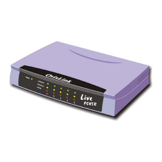
- Page 1 Live-FSH5R Fast Ethernet Switch 5 × 10/100Mbps NWay 10/100BASE-TX Fast Ethernet Switch with Auto-MDI/MDIX User’s Manual...
-
Page 2: Fcc Warning
Contents in this manual are subject to changes without prior notice. About this User’s Manual This User’s Manual aims at helping users to know the key features of Live-FSH5R Fast Ethernet Switch and to install it in a 10/100BASE-TX Fast Ethernet Local Area Network (LAN). OvisLink Corp... -
Page 3: Table Of Contents
Product Features....................... 3 Basic Features ......................... 3 PREPARATION BEFORE INSTALLATION.........4 Unpack the Package......................4 The Front Panel......................... 5 The Rear Panel........................5 Station Ports (Port #1 to #5).................... 5 DC Power Jack........................ 5 Live-FSH5R Fast Ethernet Switch User’s Manual V2.0... - Page 4 Connecting to another Switch/Hub ................11 Straight-through Cable Connection for Switch-to-Switch/hub Connection ....11 Transmission Modes ....................... 12 Station Ports (10/100BASE-TX Transmission)............12 LAN Micro segmentation through Switching Technology.......... 12 LED INDICATORS................13 Comprehensive LEDs ..................... 13 Live-FSH5R Fast Ethernet Switch User’s Manual V2.0...
- Page 5 System LED ........................13 Station Port LEDs ......................13 Power LED ........................13 Station Port LEDs ......................13 Link/Act LED ....................... 14 FDX/Col LED....................... 14 100M ..........................14 APPENDIX A PRODUCT SPECIFICATIONS ..........15 APPENDIX B TROUBLESHOOTING...............17 Live-FSH5R Fast Ethernet Switch User’s Manual V2.0...
- Page 6 Fig. 3-3 10/100BASE-TX pin assignments for RJ-45 connector ........8 Fig. 3-4 Pin assignments for straight-through cabling............ 8 Fig 3-5 Connecting the Switch to power outlet .............. 9 Fig. 5-1 Front-panel LED indicators................13 Live-FSH5R Fast Ethernet Switch User’s Manual V2.0...
- Page 7 Table of Contents Tables Table 3-1 Cabling type for 10BASE-T/100BASE-TX........... 8 Table 5-1 Station Port LEDs..................14 Live-FSH5R Fast Ethernet Switch User’s Manual V2.0...
-
Page 9: Product Overview
Live-FSH5R’s unique switching fabric provides full wire speed for all ports. With auto-sensing, Live-FSH5R automatically detects the speed of the devices you plug into, and routes the incoming data to its destination. Its auto-negotiating function allows existing devices running at different speeds to communicate easily within the same network. - Page 10 The System LEDs consist of the Power. Power LED shows Power On/Off status of the switch. The Station Port LEDs reveal the link status, half/full duplex transmission, 10/100Mbps speed mode and the collision status of each station port. For detailed LED information, refer to Chapter 5, LED Indicators. Live-FSH5R Fast Ethernet Switch User’s Manual V2.0...
-
Page 11: Product Features
- Link/Act (green) LEDsto indicate linking status and activity in 10/100Mpbs mode - FDX/Col (yellow) LEDs to indicate Half/Full Duplex transmission and collision status - 100M (red) LEDs to indicate 100 Mbps speed Cabling distance up to 100 meters for twisted-pair cable Live-FSH5R Fast Ethernet Switch User’s Manual V2.0... -
Page 12: Preparation Before Installation
2 Preparation before Installation Preparation before Installation Unpack the Package Before you begin the installation of Live-FSH5R Fast Ethernet Switch, make sure that you have all the necessary accessories that come with your package. Follow the steps below to unpack your package contents: 1. -
Page 13: The Front Panel
Appendix A, Product Specifications for detailed information. Station Ports (Port #1 to #5) Live-FSH5R Fast Ethernet Switch is equipped with 5 10/100Mbps auto-sensing and auto-negotiating ports. You can use these ports to connect to end stations, servers or other networking devices. -
Page 14: Installation Of The Switch
UTP) or shielded twisted-pair (STP) cable. Desktop Installation Live-FSH5R Fast Ethernet Switch has four rubber pads attached on each corner of its underside. These pads serve as cushionings against vibration and prevent the switch from sliding off its position. They also allow adequate ventilation space when you place the switch on top of another device. -
Page 15: Installation On Wall
3 Installation of the Switch Installation on Wall Live-FSH5R Fast Ethernet Switch can be mounted on a wall with wall anchors and screws. To mount the Switch on wall, please follow the steps below: Drill two holes, the distance between both of which should be 4 cm (such as the illustration below). -
Page 16: Fig. 3-3 10/100Base-Tx Pin Assignments For Rj-45 Connector
Note: While connectingLive-FSH5R to other hub/switch, you don’t have to use a crossover cable for connection, since Live-FSH5R performs auto-crossing over by its Auto-MDI, Auto-MDI-X function. Simply use the straight-through cable for all types of 100BASE-TX connections, either to a PC or to a networking device such as other hub or switch. -
Page 17: Connecting To Power
3 Installation of the Switch Connecting to Power Live-FSH5R is accompanied with an external power adapter unit, which is specifically designed for the line voltage and the type of AC outlet used in your location. This power adapter provides the voltage, amperage, and polarity required by the Switch (7.5V... -
Page 18: Expanding Your Network
4 Expanding your Network Expanding Your Network Live-FSH5R Fast Ethernet Switch is primarily designed as a central switching device to manage your workgroup/departmental traffic within Ethernet/Fast Ethernet. Its built-in VLAN function offers instant connection without further administration efforts. Furthermore, its secure VLAN feature offers security for virtual workgroups. With your existing Ethernet/Fast Ethernet infrastructure, you can very easily connect, expand or migrate to virtual workgroup computing in an Ethernet/Fast Ethernet environment. -
Page 19: Connecting To Another Switch/Hub
Straight-through Cable Connection for Switch-to-Switch/hub Connection Use a straight-through cable for the connection made through the station port of Live-FSH5R to any station port of the other switch/hub. Since Live-FSH5R Switch is capable of auto-crossing over by its Auto-MDI and Auto-MDI-X function, you don’t have to use a crossover cable such as is usually required for this kind of switch-to-switch/hub connection with other switch. -
Page 20: Transmission Modes
Transmission Modes Station Ports (10/100BASE-TX Transmission) All 10/100Mbps station ports of Live-FSH5R Fast Ethernet Switch utilize auto-negotiation to determine the transmission mode for any new connection. This means, if auto-negotiation is supported on both ends of the connection, the Switch is initiated to negotiate for one of the following transmission modes: •... -
Page 21: Led Indicators
5 LED Indicators LED Indicators Before connecting any network device to Live-FSH5R Fast Ethernet Switch, you should take a few minutes to look over this chapter and get familiar with the front panel LED indicators of your Switch. The front-panel LED indicators of Live-FSH5R comprise 2 sets of LEDs: System Status LEDs and Station Port LEDs. -
Page 22: Link/Act Led
Station Port LEDs Link/Act ● Green Connection is made Blinking Transmitting/Receiving No connection is made FDX/Col ● Full Duplex Yellow Half Duplex Blinking Collisions (in half duplex) 100M ● 100 Mbps Connection 10 Mbps Connection Live-FSH5R Fast Ethernet Switch User’s Manual V2.0... -
Page 23: Appendix A Product Specifications
100BASE-TX: 4-pair 100 ohm Category 5 UTP/STP (100 m) cable • LED layout System LEDs Power LED Station port LEDs for port 1 ~ 5 Link/Act LEDs FDX/Col LEDs 100M LEDs • Dimensions 169*118*29 m/m Live-FSH5R Fast Ethernet Switch User’s Manual V2.0... - Page 24 -32 ~ 122 °F / 0 ~ 50 °C • Storage Temperature - 68 ~ 149°F / -20 ~ 65 °C • Humidity < 95% (non-condensing) • Safety / EMI Certificates UL, TUV, VDE, FCC Class A, CE Live-FSH5R Fast Ethernet Switch User’s Manual V2.0...
-
Page 25: Appendix B Troubleshooting
• If you find out where the problem is but cannot solve it by yourself, or you simply cannot locate what is at fault, please contact your local dealer for technical support. Live-FSH5R Fast Ethernet Switch User’s Manual V2.0...
Need help?
Do you have a question about the Live-FSH5R and is the answer not in the manual?
Questions and answers