
Subscribe to Our Youtube Channel
Related Manuals for Air Live POE-FSH808AT


Summary of Contents for Air Live POE-FSH808AT
- Page 1 POE-FSH808AT 8-Port 48V Active POE + 2 Gigabit Uplink Web Smart Switch User’s Manual...
- Page 2 OvisLink Corp. has made the best effort to ensure the accuracy of the information in this user’s guide. However, we are not liable for the inaccuracies or errors in this guide. Please use with caution. All information is subject to change without notice All Trademarks are properties of their respective holders. AirLive POE-FSH808AT User’s Manual...
-
Page 3: Fcc Statement
Copyright and Disclaimer FCC Statement Federal Communication Commission Interference Statement This equipment has been tested and found to comply with the limits for a Class B digital device, pursuant to Part 15 of the FCC Rules. These limits are designed to provide reasonable protection against harmful interference in a residential installation. -
Page 4: Table Of Contents
4.4.2 System IP Configuration ................19 4.4.3 System Status .................... 20 4.4.4 Load Default Setting .................. 21 4.4.5 Firmware Update ..................21 4.4.6 Reboot Device ................... 22 4.5 Port Management ................22 4.5.1 Port Configuration ..................22 AirLive POE-FSH808AT User’s Manual... - Page 5 Table of Contents 4.5.2 Port Mirroring ..................... 24 4.5.3 Bandwidth Control ..................25 4.5.4 Broadcast Storm Control ................26 4.5.5 POE Configuration ..................27 4.6 VLAN Setting ................... 28 4.6.1 VLAN Mode ....................29 4.6.2 VLAN Member ................... 30 4.6.3 Multi to 1 Setting ..................33 4.7 Per Port Counter Port ..............
-
Page 6: Introduction
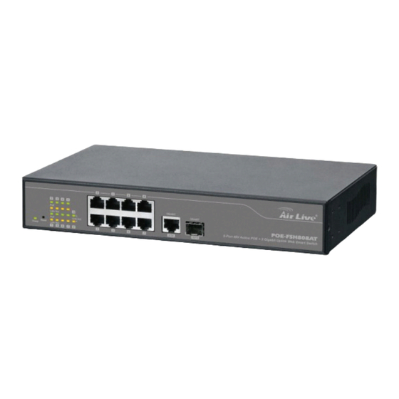
1. Introduction Introduction 1.1 Overview The POE-FSH808AT is a Power Control Active POE Switch. It was designed for easy installation and high performance in an environment where traffic is on the network and the number of users increases continuously. It consists of 8 10/100Mbps RJ-45 ports and 1 Gigabit RJ-45 plus 1 Gigabit SFP Port. The 8 10/100Mbps RJ-45 ports are built with 48V Active PoE technology. -
Page 7: Guide To The Chapters
For detailed installation instruction, please see chapter 2 for more information. Power-On the switch The POE-FSH808AT has a built-in power supply to operate with 100 ~ 240V AC, 50 ~ 60Hz power source. The AC power cord connector is located at the rear of the unit and the On/Off switch is next to the connector. -
Page 8: Installation Steps
Step4. Open your web browser and enter "192.168.2.1" to get into the switch's web management. Step5. Enter "admin" for username and "airlive" for password. Step6. Go to "Port Management", and then select "PoE". Step7. Turn on the port number where you connect the device. AirLive POE-FSH808AT User’s Manual... - Page 9 1. Introduction Step8. If you want to install the switch on the 19" rack, please install the mounting kit (optional). Step9. Please see Chapter 4 for further configurations. AirLive POE-FSH808AT User’s Manual...
-
Page 10: Installation Of The Switch
IP address, password, and LED table for user’s reference. 2.1 Unpack the Package Before you begin the installation of POE-FSH808AT Management Switch, make sure that you have all the necessary accessories that come with your package. Follow the steps below to unpack your package contents: 1. -
Page 11: Hardware Overview
These ports also support the automatic MDI/MDIX crossover detection function, providing true “plug and play” capability. Just plug-in the network cable to the hub directly and regardless if the end node is a NIC (Network Interface Card) or switch and hub. AirLive POE-FSH808AT User’s Manual... -
Page 12: Installation Site Preparation
2.3 Installation Site Preparation You can mount POE-FSH808AT either on desktop or on a 19-inch rack. If you plan to mount the switch on desktop, please choose a steady, level surface in a well-ventilated area that is free from excessive dust. In any case, the installation site chosen for your switch has to comply with the following requirements: ... -
Page 13: Rack Mounting
Leave at least 10cm(4 inch) of space around the switch to allow heating dissipation 2.4 Rack Mounting The POE-FSH808AT can be mounted on a standard size 19-inch rack, which can in turn be placed in a wiring closet with other equipments. -
Page 14: Desktop Installation
Attaching the Switch to a 19-inch rack 2.5 Desktop Installation The POE-FSH808AT has four rubber pads attached on each corner of its underside. These pads serve as cushioning against vibration and prevent the switch from sliding off its position. They also allow adequate ventilation space when you place the switch on top of another device. -
Page 15: Cabling Requirements
Auto MDI/MDI-X function The POE-FSH808AT is equipped with Auto-MDI/MDI-X function, which allows you to use straight-thru cable even when connecting to another switch/hub. Simply use the straight-through cable for all types of 10/100BASE-TX connections, either to a PC or to a networking device such as other hub or switch. -
Page 16: Reset To Default
Please take the following steps to reset the Web Smart Switch back to the original default: Step 1. Turn on the POE-FSH808AT. Step 2. Press and hold the reset button continuously for 10 seconds and release the reset button. -
Page 17: Led Indicators
3. Installation LED Indicators Before connecting any network device to POE-FSH808AT, you should take a few minutes to look over this chapter and get familiar with the front panel LED indicators of your Switch. 3.1 Comprehensive LEDs 3.2 LED Table... -
Page 18: Web Management
4. Web Management Web Management The POE-FSH808AT can be configured by web based interface, including administrator, port management, VLAN setting, per port counter, trunk setting, QoS setting, security filter, configuration/ backup/recovery, miscellaneous, log out, and so on. The device based smart switch supports main stream browsers, such as IE, Firefox and Chrome…etc to configure... - Page 19 If there is no network status icon on the task bar, please go to the “Start -> Settings -> Network -> Local Connection” of the task bar’s Start menu. Step 2. Clock on the “property” icon. Step 3. Double click on the “Internet Protocol (TCP/IP) AirLive POE-FSH808AT User’s Manual...
-
Page 20: Remote Management
192.168.2.1 Click “OK” after finish entering the IP. * Note1: The POE-FSH808AT has DHCP client ability. This allows DHCP server (or router) to assign IP automatically. However, we do not recommend turning on the DHCP client because the DHCP server assign the IP randomly. The DHCP client should be used only when connecting directly to Cable Modem (for remote management) whose service provider uses DHCP for IP assignment. - Page 21 In the diagram above, the router has the WAN (given by the ISP) port IP address “201.100.1.5” and LAN port address “192.168.0.254”. The switch’s IP is “192.168.0.200”. Please follow the instruction below to setup the router and switch for remote access: AirLive POE-FSH808AT User’s Manual...
-
Page 22: Get Into The Web Management
Step 2. Enter the switch’s IP address in the Address field and press enter. Step 3. When prompt for User’s name and Password, enter the following information: User’s Name: admin Password: airlive You should see the following welcome screen after the process is completed: AirLive POE-FSH808AT User’s Manual... -
Page 23: Administrator
When a port is plugged in, the switch’s image will show a “plug” on the corresponding port. 4.4 Administrator There are many management functions can be set or performed if you click the Administrator on Home Page, including: AirLive POE-FSH808AT User’s Manual... -
Page 24: Authentication Configuration
4.4.1 Authentication Configuration This page shows authentication configuration information. User can set new Username and Password in this page. 4.4.2 System IP Configuration This page shows system configuration including the current IP address and sub-net mask and gateway. AirLive POE-FSH808AT User’s Manual... -
Page 25: System Status
This page is used to check the status of switch, including Switch MAC address and software version. The comment field allows the network administrator to input an easy-to-remember nickname for this switch. The legal characters are “a~z” and “A~Z”, “_”, “-“, “+”, “0 ~9”, excluding special character. AirLive POE-FSH808AT User’s Manual... -
Page 26: Load Default Setting
Boot Loader, so the Boot Loader will keep intact. Even though the power is turned off or the cable link fails during the firmware update procedure, the Boot loader will restore the code to firmware update page. AirLive POE-FSH808AT User’s Manual... -
Page 27: Reboot Device
POE Configuration In the following sessions, we will talk in detail about the management functions under the Port Management menu. 4.5.1 Port Configuration In Port Configuration, you can set and view the operation mode for each port. AirLive POE-FSH808AT User’s Manual... - Page 28 Addr. Learning: When the Auto-Negotiation column is set as Disable, users have to set this column as Enable or Disable. Select Port No.: Tick the check boxes beside the port numbers being set. AirLive POE-FSH808AT User’s Manual...
-
Page 29: Port Mirroring
This field indicates the port 9 is link up and run as 1G Full, Flow Control Enabled. Current Status: Displays current port status. Setting Status: Displays current status. Click "Update" to have the configuration take effect. 4.5.2 Port Mirroring The port mirroring function is accomplished by setting the following items. AirLive POE-FSH808AT User’s Manual... -
Page 30: Bandwidth Control
This page allows the setting of the bandwidth for each port. The TX rate and Rx rate can be filled with the number ranging from 1 to 255. This number should be multiplied by the selected bandwidth resolution to get the actual bandwidth. AirLive POE-FSH808AT User’s Manual... -
Page 31: Broadcast Storm Control
The switch implements a broadcast storm control mechanism. Tick the check boxes to have them beginning to drop incoming broadcast packets if the received broadcast packet counts reach the threshold defined. Each port’s broadcast storm protection function can be enabled individually by ticking the check boxes. AirLive POE-FSH808AT User’s Manual... -
Page 32: Poe Configuration
While type 10 to port 1, that means 10x2000 packets can be sent in one second. 4.5.5 POE Configuration User could know per PoE port out power status in this page and also enable or disable per port. AirLive POE-FSH808AT User’s Manual... -
Page 33: Vlan Setting
There are many management functions can be set or performed if you click the VLAN Setting on Home Page, including: VLAN Mode VLAN Member Multi to 1 Setting In the following sessions, we will talk in detail about the management functions under the VLAN Setting menu. AirLive POE-FSH808AT User’s Manual... -
Page 34: Vlan Mode
Port Based VLAN Mode Tag Mode: Add Tag: The outgoing packet of the selected port will be inserted a 802.1Q tag. Use this setting for your Up and Downlink Ports in your VLAN Tagged Network. AirLive POE-FSH808AT User’s Manual... -
Page 35: Vlan Member
Read, and then select or deselect the ports that are on the same VLAN group. In this configuration mode you do not need to worry about defining VLAN groups and VLAN IDs. AirLive POE-FSH808AT User’s Manual... - Page 36 After deleted, the VLAN and its member port setting is gone. Update: Modify the existing VLAN setting. Select the VID, the below settings display, you can change the settings and then press the Update button to update the settings. AirLive POE-FSH808AT User’s Manual...
- Page 37 Second, enter “100” in the field right of VID Setting, then select or deselect which ports are member of that group. Your up and downlink ports need to be the member of every existing group. If the port joins different VLAN groups, the VID Source Port allows you to define the PVID. AirLive POE-FSH808AT User’s Manual...
-
Page 38: Multi To 1 Setting
4.7 Per Port Counter Port This page provides port counter for each port. There are 4 groups of statistics in total. These 4 categories cannot work simultaneously. Once you change the counter category, the counter will be cleared automatically. AirLive POE-FSH808AT User’s Manual... - Page 39 CRC error. Once your see CRC error increasing here, please notice that there may be hardware issue, the possible reason could be switch port failure, cable lose/broken, cable/fiber connector failure...etc. Update: Select the existing Counter Mode and click Update, the below statistic table will be updated. AirLive POE-FSH808AT User’s Manual...
-
Page 40: Qos Setting
There are many management functions can be set or performed if you click the QoS Setting on Home Page, including: Priority Mode Class of service Configuration In the following sessions, we will talk in detail about the management functions under the QoS Setting menu. AirLive POE-FSH808AT User’s Manual... -
Page 41: Priority Mode
Weighted-and-round-robin (WRR) mode. When this mode is selected, the traffic will be forwarded according to ratio of the number set of Low/High weight user configured. 4.8.2 Port, 802.1p, IP/DS based The page allows you to enable Port Based, VLAN Tag or IP/DS mode of COS. AirLive POE-FSH808AT User’s Manual... -
Page 42: Tcp/Udp Port Based
The number set of the high priority is 10,18,26,34,46,48,56; the others are mapped to low priority. 4.8.3 TCP/UDP Port Based This page allows user to define the Option type of the pre-defined protocols or user-defined protocols. Select the Option of the Protocol as below figure shown. AirLive POE-FSH808AT User’s Manual... - Page 43 For example, UDP/TCP port = 65535(Hex 0xFFFF = 11111111 11111111) and mask = 5 (Hex 0x0005 = 00000000 00000101), this means 65530 (11111111 11111010), 65531(11111111 11111011), 65534(11111111 11111110) and 65535(11111111 11111111) are all taken into account. UDP/TCP port =65535 and mask=0, this means only 65535 is taken into account. AirLive POE-FSH808AT User’s Manual...
-
Page 44: Security
Select Port: Select the port number and click "Read" button. If you don't enter any MAC Address before, the address is blank. If you have entered any MAC address, the field will display the MAC addresses your previously entered. AirLive POE-FSH808AT User’s Manual... -
Page 45: Tcp/Udp Filter
The” deny” function makes the switch drop the selected protocol and forward other protocols. The protocol is checked at the selected secure WAN port. And it should be set at the server side. AirLive POE-FSH808AT User’s Manual... -
Page 46: Spanning Tree
The switch supports IEEE 802.1D-2004 RSTP protocol, the RSTP protocol can backward compatible to legacy Spanning Tree Protocol (STP) and 802.1w Rapid Spanning Tree Protocol (RSTP). 4.10.1 STP Bridge Settings The Table allows you to configure STP Mode and the system time settings. AirLive POE-FSH808AT User’s Manual... - Page 47 Click Update to have the configuration take effect. The below table shows the Bridge Status and Root Switch's Status. The Bridge Status shows the STP configuration of the switch. The Root Status shows the Root Switch's Information of the STP domain. AirLive POE-FSH808AT User’s Manual...
-
Page 48: Stp Port Settings
This page allows you to change the STP port setting. Select the port number, type the value of the Priority and Root Path Cost. Click "Submit" to apply the settings. AirLive POE-FSH808AT User’s Manual... -
Page 49: Loopback Detection Settings
4.10.3 Loopback Detection Settings In some condition, the user may incorrectly connect the wrong port and lead the network loop. The unknown broadcast, multicast may crash the whole network. The Loopback Detection feature can help you leave the risk. AirLive POE-FSH808AT User’s Manual... -
Page 50: Trunk Setting
This switch may use Port ID, Source MAC Address, Destination MAC Address, or a combination of Source MAC Address and Destination MAC Address to be the selection for Trunk Hash Algorithm. AirLive POE-FSH808AT User’s Manual... - Page 51 System Priority: This column allows you to enable or disable Loopback Detection function. Link Aggregation Algorithm: MAC Src: Hash Algorithm based on Source MAC Address. MAC Src&Dst: Hash Algorithm based on Source & Destination MAC Address XOR result. AirLive POE-FSH808AT User’s Manual...
-
Page 52: Backup/Recovery
The user can save configuration file to a specified file. If the user wants to recover the original configuration, which is saved at the specified path, just enter the password and then press the “Update” button. Finally the original configuration of the switch will be recovered. AirLive POE-FSH808AT User’s Manual... -
Page 53: Miscellaneous
4. Web Management 4.13 Miscellaneous Miscellaneous setting is used to configure output queue aging time, VLAN stride and IGMP snooping. AirLive POE-FSH808AT User’s Manual... - Page 54 1 and version 2 without the intervention of CPU. The IGMP report and leave packets are automatically handled by the switch. The next setting, IGMP Leave Packet can be enabled or disabled. After enabled, the Leave packet will be forwarded to IGMP router ports. AirLive POE-FSH808AT User’s Manual...
-
Page 55: Logout
VLAN striding and ignores the VLA 4.14 Logout The administrator has write access for all parameters governing the onboard agent. User should therefore assign a new administrator password as soon as possible, and store it in a safe place. AirLive POE-FSH808AT User’s Manual... -
Page 56: Appendix A: Product Specifications
Web-base Management, Graphic User Interface, Configuration Back and Restore…etc. 1000Mbps port - 1,488,000pps Filtering/Forwarding 100Mbps port - 148,800pps Rates 10Mbps port - 14,880pps 10BaseT Cat. 3, 4, 5 UTP/STP Transmission Media 100BaseTX Cat. 5 UTP/STP 1000BaseT Cat. 5 UTP/STP AirLive POE-FSH808AT User’s Manual... - Page 57 Power Consumption Operating:0 to 45℃ Temperature Storage: -20 to 90℃ 10 to 90% RH (non-condensing) Humidity FCC Class A, CE Certifications 44 × 266 × 160 mm (H x W x D) Dimensions 1.8 kg Weight AirLive POE-FSH808AT User’s Manual...
-
Page 58: Appendix B: Troubleshooting
Please take the following steps to reset the Web Smart Switch back to the original default: Step1: Turn on the POE Switch Step2: Press and hold the reset button continuously for 5 seconds and release the reset button. AirLive POE-FSH808AT User’s Manual... - Page 59 Step3: The switch will reboot for 20 seconds and the configuration of switch will back to the default setting Key in the user ID and the password to pass the authentication as following, IP: 192.168.2.1 ID: admin Password: airlive AirLive POE-FSH808AT User’s Manual...
Need help?
Do you have a question about the POE-FSH808AT and is the answer not in the manual?
Questions and answers