Lexmark E460dn Service Manual
Mfps & printers
Hide thumbs
Also See for E460dn:
- User manual (179 pages) ,
- Brochure & specs (6 pages) ,
- Media manual (4 pages)
Table of Contents
Advertisement
Revision Date: July 1, 2013
Lexmark™ E460dn
Lexmark E460dw
4513-630
4513-63W
4513-6EW
• Table of contents
• Start diagnostics
• Safety and notices
• Trademarks
• Index
Lexmark and Lexmark with diamond design are
trademarks of Lexmark International, Inc., registered
in the United States and/or other countries.
Advertisement
Table of Contents

Related Manuals for Lexmark E460dn


Summary of Contents for Lexmark E460dn
- Page 1 Lexmark E460dw 4513-630 4513-63W 4513-6EW • Table of contents • Start diagnostics • Safety and notices • Trademarks • Index Lexmark and Lexmark with diamond design are trademarks of Lexmark International, Inc., registered in the United States and/or other countries.
- Page 2 Lexmark, Lexmark with diamond design and MarkVision are trademarks of Lexmark International, Inc., registered in the United States and/or other countries. PCL® is a registered trademark of the Hewlett-Packard Company.
-
Page 3: Table Of Contents
4513-630, -63W, -6EW Table of contents Table of contents ............iii Notices and safety information . - Page 4 4513-630, -63W, -6EW Media occasionally mispicks or picks multiple sheets at once ......2-29 Media skews ..............2-29 Media “trees,”...
- Page 5 4513-630, -63W, -6EW Duplex Feed 1 ............. . 3-11 Input Tray Tests .
- Page 6 Lexmark E460dw controller board ............5-3 Lexmark E460dn, E460dw controller board connector pin values ......5-4 Preventive maintenance .
-
Page 7: Notices And Safety Information
4513-630, -63W, -6EW Notices and safety information The following laser notice labels may be affixed to this printer. Laser notice The printer is certified in the U.S. to conform to the requirements of DHHS 21 CFR Subchapter J for Class I (1) laser products, and elsewhere is certified as a Class I laser product conforming to the requirements of IEC 60825-1. - Page 8 4513-630, -63W, -6EW Avisos sobre el láser Se certifica que, en los EE.UU., esta impresora cumple los requisitos para los productos láser de Clase I (1) establecidos en el subcapítulo J de la norma CFR 21 del DHHS (Departamento de Sanidad y Servicios) y, en los demás países, reúne todas las condiciones expuestas en la norma IEC 60825-1 para productos láser de Clase I (1).
- Page 9 4513-630, -63W, -6EW Laserilmoitus Tämä tulostin on sertifioitu Yhdysvalloissa DHHS 21 CFR Subchapter J -standardin mukaiseksi luokan I (1) - lasertuotteeksi ja muualla IEC 60825-1 -standardin mukaiseksi luokan I lasertuotteeksi. Luokan I lasertuotteita ei pidetä haitallisina. Tulostimen sisällä on luokan IIIb (3b) laser, joka on nimellisteholtaan 7 mW:n galliumarsenidilaser ja toimii 655 - 675 nanometrin aallonpituuksilla.
- Page 10 4513-630, -63W, -6EW Avís sobre el Làser Segons ha estat certificat als Estats Units, aquesta impressora compleix els requisits de DHHS 21 CFR, apartat J, pels productes làser de classe I (1), i segons ha estat certificat en altres llocs, és un producte làser de classe I que compleix els requisits d’IEC 60825-1.
- Page 11 4513-630, -63W, -6EW Notices and safety information...
- Page 12 4513-630, -63W, -6EW Service Manual...
-
Page 13: Lithium Warning
4513-630, -63W, -6EW Lithium warning CAUTION This product contains a lithium battery. THERE IS A RISK OF EXPLOSION IF THE BATTERY IS REPLACED BY AN INCORRECT TYPE. Discard used batteries according to the battery manufacturer’s instructions and local regulations. Safety information •... - Page 14 4513-630, -63W, -6EW Sicherheitshinweise • Die Sicherheit dieses Produkts basiert auf Tests und Zulassungen des ursprünglichen Modells und bestimmter Bauteile. Bei Verwendung nicht genehmigter Ersatzteile wird vom Hersteller keine Verantwortung oder Haftung für die Sicherheit übernommen. • Die Wartungsinformationen für dieses Produkt sind ausschließlich für die Verwendung durch einen Wartungsfachmann bestimmt.
- Page 15 4513-630, -63W, -6EW Informació de Seguretat • La seguretat d'aquest producte es basa en l'avaluació i aprovació del disseny original i els components específics. El fabricant no es fa responsable de les qüestions de seguretat si s'utilitzen peces de recanvi no autoritzades. •...
-
Page 16: Preface
4513-630, -63W, -6EW Preface This manual contains maintenance procedures for service personnel. It is divided into the following chapters: General information contains a general description of the printer and the maintenance approach used to repair it. Special tools and test equipment, as well as general environmental and safety instructions, are discussed. - Page 17 4513-630, -63W, -6EW CAUTION This type of caution indicates a hot surface. CAUTION This type of caution indicates a tipping hazard. -xvii Conventions...
- Page 18 4513-630, -63W, -6EW -xviii Service Manual...
-
Page 19: General Information
The Lexmark™ E460dn and E460dw are workgroups. This book contains information on E460dn and E460dw. For more information on E260d and E260dn, see the 4513-220, -230 service manual. For information on E360d and 360dn, see the 4513-420, -430 service manual. -
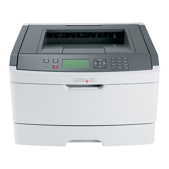
Page 20: Overview Of The Operator Panel
4513-630, -63W, -6EW Overview of the operator panel The control panel consists of these items: • A 4-line, liquid crystal display (APA) that can show both graphics and text • Eight buttons: Back , Menus , Stop , Select , and Navigation (up arrow , down arrow... -
Page 21: Specifications
4513-630, -63W, -6EW Specifications Memory 4513-63W 4513-630 Item 4513-6EW Lexmark E460dn Lexmark E460dw Standard memory 64MB 64MB Maximum memory 576MB 576MB Optional memory ✔ ✔ 128MB ✔ ✔ 256MB ✔ ✔ 512MB Optional flash memory ✔ ✔ 64MB ✔ ✔... -
Page 22: Connectivity And Compatibility
4513-630, -63W, -6EW Connectivity and compatibility 4513-63W 4513-630 Item 4513-6EW Lexmark E460dn Lexmark E460dw Data stream emulations ✔ ✔ Host based printing ✔ ✔ PCL 5e and PCL 6 ✔ ✔ PostScript 3 ✔ ✔ PPDS migration tool ✔ ✔... -
Page 23: Media Trays And Supply Capacity
4513-630, -63W, -6EW Media trays and supply capacity 4513-63W 4513-630 Item 4513-6EW Lexmark E460dn Lexmark E460dw Available input trays ✔ ✔ Integrated 250-sheet tray ✔ ✔ 50-sheet MP feeder 1-sheet manual feed slot Optional input sources ✔ ✔ 250-sheet drawer ✔... -
Page 24: Types Of Print Media
4513-630, -63W, -6EW Types of print media Note: Ensure trays are properly loaded. Never mix media types within a tray. Source Sizes Types Weight Input capacity* (sheets) Input tray 1 A4, A5, A6,JIS¹-B5, Plain paper, 60-90 g/m² • 250 paper letter, legal, executive, recycled, labels, •... -
Page 25: Tips On Preventing Jams
4513-630, -63W, -6EW Tips on preventing jams Paper path Paper path A – B 125.3 mm Manual feed sensor B – C 9.0 mm Upper end feed rolls C – D 59.8 mm Input sensor D – E 44.9 mm Transfer roll E –... -
Page 26: Tools
Have any exposed adhesive when the flap is in the sealed position • Use only recommended media. Refer to the Card Stock & Label Guide available on the Lexmark Web site at www.lexmark.com for more information about which media provides optimum results for the current printing environment. -
Page 27: Acronyms
4513-630, -63W, -6EW Acronyms Autocompensator Mechanism (or paper feed) Analog-to-digital Converter ASIC Application Specific Integrated Circuit Complete Bill Of Material Development Roll (of print cartridge/photoconductor system) DIMM Dual In-Line Memory Module External Network Adapter Field Replaceable Unit Host Based Printing HVPS High Voltage Power Supply Liquid Crystal Diode... - Page 28 4513-630, -63W, -6EW 1-10 Service Manual...
-
Page 29: Diagnostics Information
4513-630, -63W, -6EW 2. Diagnostics information Start CAUTION: Unplug power from the printer before connecting or disconnecting any cable, assembly, or electronic card. This is a precaution for personal safety and to prevent damage to the printer. Use the service error code, user status message, user error message, symptom table, service checks, and diagnostic aids in this chapter to determine the corrective action necessary to repair a malfunctioning printer. -
Page 30: Overview Of The Operator Panel And Menus
4513-630, -63W, -6EW Overview of the operator panel and menus The operator panel on your printer is a 4-line, back-lit, grayscale display that can show both graphics and text. The Back, Menu, and Stop buttons are located to the left of the display, the navigation buttons are located below the display, and the numeric pad is located to the right of the display. - Page 31 4513-630, -63W, -6EW Operator panel (Continued) Button Function Keypad Use the keypad to enter numbers or symbols on the display. Indicator light The indicator light indicates printer status. • If the light is off, then the printer power is off. •...
-
Page 32: Diagram Of The Printer Menus
4513-630, -63W, -6EW Diagram of the printer menus The diagram shows the menu index on the operator panel and the menus and items available under each menu. Not all menus or selections will be available in all situations. These are accessed through the driver. Paper Menu Job Menu Finishing Menu... -
Page 33: Messages And Error Codes
4513-630, -63W, -6EW Messages and error codes User attendance messages The printer control panel displays messages describing the current state of the printer and indicates possible printer problems that must be resolved. This topic provides a list of all printer messages, explains what they mean, and tells how to clear the messages. - Page 34 4513-630, -63W, -6EW User attendance messages (Continued) Message Action Load <src> with <Custom Type Name> • Load the input source with the correct type and size media. • Cancel the current job. Load <src> with <Custom String> Load <src> <size> Load <src>...
- Page 35 4513-630, -63W, -6EW User attendance messages (Continued) Message Action Prog System Code The printer is programming new system code. Wait for the message to DO NOT POWER OFF clear and the printer to reset. Warning: Do not turn the printer off while this message is displayed. Ready Send a job to print.
-
Page 36: Cartridge Error Messages
4513-630, -63W, -6EW Cartridge error messages Error Description Action 30.XX Cartridge errors 30.01 No bucket transition out of the top bucket. If the cartridge Replace the cartridge. has not been refilled, then it usually is a mechanical problem with the cartridge. During development, it could also have the wrong chip installed. -
Page 37: Paper Jam Error Codes (200-Series)
4513-630, -63W, -6EW Error Description Action 32.01 MC CC Mismatch. Incorrect cartridge installed in printer or Replace the cartridge. printer settings are incorrect (based on cartridge capacity). 32.02 Down-level device installed on cartridge. 32.03 Down-level device installed on cartridge. 32.04 Unknown toner type indicated by the device. - Page 38 4513-630, -63W, -6EW Error Description Action 200.09 Transfer servo never started Inspect the LVPS/HVPS. See “Controller board service check” on page 2-23. 200.12 Media detected at manual feeder sensor when not Carefully remove the tray and notice if the leading expected.
- Page 39 4513-630, -63W, -6EW Error Description Action 200.24 The measured gap at the input sensor is too small to Verify that the media is approved. Inspect the wear meet the video delivery requirements. (There is not strips in the tray, and replace if they are worn. enough time since prior image finished to start new image) 200.26...
- Page 40 4513-630, -63W, -6EW Error Description Action 201.00 Paper jam between input and exit sensor Remove the toner cartridge/PC kit and check for obstructions between the input sensor and the fuser. if the media continues to stop at the entrance or in the fuser, then replace the fuser.
- Page 41 4513-630, -63W, -6EW Error Description Action 202.32 Long media or shingled multi feed stopped before Check the paper setting and correct if needed. While sending to duplex. feeding along the media, and immediately after it enters the output bin, open the reat door and obscure the trailing edge and the sensor flag.
- Page 42 4513-630, -63W, -6EW Error Description Action 242.10 Second pick attempt failed from Tray 2 Remove Tray 2 and inspect for obstruction in the paper path. Check the pick tires for wear or paper dust. Replace if necessary. Check the wear strips and replace if necessary.
-
Page 43: Service Error Codes
4513-630, -63W, -6EW Service error codes Service error codes are generally non-recoverable except in an intermittent condition when the printer can be put into POR to temporarily recover from the error condition. Error Description Action Engine software service errors 900.xx Code detected unusual event of timing “Service software service check”... - Page 44 4513-630, -63W, -6EW Error Description Action 922.04 Hot roll timed out in trying to reach the final lamp Replace the fuser. See “Fuser service check” detection temperature. on page 2-26. 922.05 Did not roll over to a steady state control in time after the hot roll lamp detection.
- Page 45 4513-630, -63W, -6EW Error Description Action Printhead service errors 930.00 Wrong printhead installed Replace the printhead. See “Printhead service check” on page 2-38. 931.00 No first hsync 931.01 No first hsync 932.00 Lost hsyncs 932.01 Lost hsyncs 933.01 Printhead boost signal failure 934.00 Mirror motor lost lock.
- Page 46 4513-630, -63W, -6EW Error Description Action 936.01 No lock detected at normal motor start Replace the main motor gear drive. See “Main motor service check” on page 2-27 936.02 No lock detected at motor start for motor ID 936.03 No halls detected at motor start 936.04 Failed to stop within timeout Replace the main motor gear drive.
- Page 47 4513-630, -63W, -6EW Error Description Action Firmware or controller board errors 959.01 Controller verification failure of pensive boot code Call the next level of support to update the firmware, or replace the controller board. See “Controller board service check” on 959.02 Failure to authenticate Signature Verification Code page...
- Page 48 4513-630, -63W, -6EW Error Description Action 980.xx Engine experiencing unreliable communication with the Call the next level of support. specified device 981.xx Engine protocol violation detected by the specified device 982.xx Communications error detected by the specified device 983.xx Invalid command received by the specified device 984.xx Invalid command parameter received by the specidied Call the next level of support.
-
Page 49: Symptom Tables
4513-630, -63W, -6EW Symptom tables POST symptom table Symptom Action The main motor, cooling fan, and fuser do not come “Cover interlock switch service check” on page 2-24. POST completes, but the LCD does not come on. “Operator panel service check” on page 2-28. -
Page 50: Printer Symptom Table
4513-630, -63W, -6EW Printer symptom table Symptom Action Fan noisy or fan not working. “Cooling fan service check” on page 2-24. Fuser parts melted. “LVPS/HVPS service check” on page 2-26. Toner not fused to the media. “Fuser service check” on page 2-26 “Solving print quality problems”... -
Page 51: Service Checks
4513-630, -63W, -6EW Service checks Service checks which involve measuring voltages on the LVPS/HVPS (low voltage power supply/ high voltage power supply board) should be performed with the printer positioned on its back side. Note: When making voltage readings, always use frame ground unless another ground is specified. -
Page 52: Cooling Fan Service Check
4513-630, -63W, -6EW Controller board service check (Continued) Action LVPS/HVPS Verify main power to controller board With the printer off, unplug the LPS/HVPS cable at J502 on the controller board. Verify grounds on pins 10, 12, 14, 16 and 18 for both the cable and the controller board. If any of these grounds are incorrect, then check the cable for continuity. -
Page 53: Dead Machine Service Check
4513-630, -63W, -6EW Dead machine service check CAUTION: Check the AC line voltage. The voltage should be within the following limits: • 100 V ac (volts alternating current) – 127 V ac for the 110 V printer • 200 V ac – 240 V ac for the 220 V printer Action Unplug the printer. -
Page 54: Fuser Service Check
4513-630, -63W, -6EW Fuser service check When toner is partially fused to the media, it is usually caused by low fuser temperature. The line voltage to the printer must be within the following limits: • 100 V ac-127 V ac for the 110 V model printer •... -
Page 55: Main Motor Service Check
When either support. of these cards is new, • If these voltages are not correct, then see “Lexmark E460dn, E460dw controller it obtains the settings board connector pin values” on page 5-4, or replace the controller board. See from the other card. -
Page 56: Operator Panel Service Check
4513-630, -63W, -6EW Operator panel service check Inspect the operator panel cable for damage. Make sure the cable is plugged in securely. Run POST, and check each light for proper operation. See “Power–On Self Test (POST) sequence” on page 2-1. LCD Operator panel service check Action Operator panel (LCD) -
Page 57: Media Never Picks
4513-630, -63W, -6EW Media never picks Action Paper feed (pick tires) tray 1 Open the left cover, and verify that the solenoids and clutches are functioning Paper feed (pick tires) tray 2 when an attempt is made to feed the media. Media drive ASM Make sure the rubber tires on the ACM are installed and clean. -
Page 58: Media "Trees," Wrinkles, Stacks Poorly, Or Curls
4513-630, -63W, -6EW Media “trees,” wrinkles, stacks poorly, or curls Action Fuser This problem is most likely due to a worn backup roll. It causes the printer to run hotter than required for the media being printed. Excessive heat can cause media treeing problems, poor stacking, or curl. -
Page 59: Print Quality Service Checks
4513-630, -63W, -6EW Print quality service checks Note: Ensure the cover closes tightly. A gap in the opening may allow light to expose the photoconductor, resulting in a ‘dirty’ print. Extreme environmental conditions, temperatures, and humidity will affect the print quality. -
Page 60: Black Page
4513-630, -63W, -6EW Black page Note: Incorrect laser exposure or incorrect charging of the photoconductor causes an all black page. Always verify the same results from a different print cartridge assembly and developer before proceeding. Action Toner electrodes (not Check the three rearward electrodes below the toner cartridge assembly for contamination, a FRU) damage, or a short to ground. -
Page 61: Partial Blank Image/White Spots (No Repeating Pattern)
4513-630, -63W, -6EW Partial blank image/white spots (no repeating pattern) Action Toner cartridge (not a Remove the toner cartridge assembly, and gently shake the assembly to evenly distribute FRU) the toner. Check to make sure that the laser light path is not blocked. If toner cartridge is low, then try a new one. -
Page 62: Light Print
4513-630, -63W, -6EW Light print Action Toner cartridge (not a Make sure the toner cartridge and photoconductor kit are installed correctly and that the FRU) toner cartridge is not low on toner. If the problem continues, then install a new toner cartridge. Recheck condition before replacing photoconductor kit, if necessary. -
Page 63: Solving Print Quality Problems
4513-630, -63W, -6EW Solving print quality problems Note: Refer to the print defects guide at the end of the manual for repeating defects. Print quality problems Problem Cause / action Light or blurred Light print characters. “Light print” on page 2-34. - Page 64 4513-630, -63W, -6EW Print quality problems (Continued) Problem Cause / action Toner smears or rubs • Toner is not being fused to the paper. Replace the fuser. off the page. • Change the media texture setting in the driver. If special media is being used, such as card stock or labels, then be sure to select the correct media type.
- Page 65 4513-630, -63W, -6EW Print quality problems (Continued) Problem Cause / action The printer is on and • Make sure the parallel or USB cable is not damaged and is firmly plugged into the indicates ready, but connector on the back of the printer. nothing prints.
-
Page 66: Printhead Service Check
4513-630, -63W, -6EW Print quality problems (Continued) Problem Cause / action Unexpected • Ensure correct printer driver is being used. characters print, or • Select hex trace mode to determine what the problem is. characters are • Restore factory defaults. missing. -
Page 67: Service Software Service Check
Note: Before troubleshooting, determine the operating system used when the error occured. If possible determine whether a PostScript or PCL file was sent to the device when the error occured. Ask the customer which Lexmark Solutions applications are installed on the device. Step Action and questions POR the device. - Page 68 Go to step 15. Go to step 16. to the device. Does the 900.xx error reoccur? Install a Lexmark recommended memory Go to step 31. Problem resolved. option. Send a print job to the device. Does the 900.xx error reoccur? Is there a modem installed on the device? Go to step 17.
- Page 69 4513-630, -63W, -6EW Step Action and questions Are there any ISP (internal solutions port) Go to step 22. Problem resolved. options installed? Reinstall the first ISP option. Restart the Go to step 24. Go to step 23. device. Does the 900.xx error reoccur? Run a job to test the option.
-
Page 70: Transfer Roll Service Check
Turn the printer on and check the voltages on connector J28 on the controller board. See the wiring diagram at the end of the service manual, or “Lexmark E460dn, E460dw controller board connector pin values” on page 5-4 for the J28 connector. -
Page 71: Diagnostic Aids
4513-630, -63W, -6EW 3. Diagnostic aids This chapter explains the tests and procedures to identify printer failures and verify repairs have corrected the problem. Accessing service menus There are different test menus that can be accessed during POR to identify problems with the printer. Configuration Menu 1. -
Page 72: Configuration Menu (Config Menu)
4513-630, -63W, -6EW Configuration menu (CONFIG MENU) Entering Configuration Menu Turn off the printer. Press and hold Turn on the printer. Release the buttons when the clock displays. Available menus The menus display on the operator panel in the order shown: Maintenance Count Value “Maintenance Count Value (Maint Cnt Value)”... -
Page 73: Maintenance Count Value (Maint Cnt Value)
4513-630, -63W, -6EW Maintenance Count Value (Maint Cnt Value) The Maintenance Count Value displays the current value of the Maintenance Kit counter which provides a rough gauge of the printer’s usage. A simplex print job increases the counter by one, and a duplex print job increases the counter by two. -
Page 74: Reports
4513-630, -63W, -6EW Reports The Reports menu contains two selections: Menu Settings Page and Event Log. Menu Settings Page To print the Menu Settings page, press . Press to return to the Configuration menu. Event Log The event log provides a history of printer errors. The event log can only be printed in the Configuration menu. -
Page 75: Action For Prompts
4513-630, -63W, -6EW Action For Prompts This setting determines which input source receives paper-related or envelope-related change prompts when they occur. Press to enter Action For Prompts from the Configuration Menu. The following displays: Action For Prompts ✔*Prompt user Continue Use Current to select a prompt. -
Page 76: Diagnostics Menu
4513-630, -63W, -6EW Diagnostics menu Entering Diagnostics menu Turn off the printer. Press and hold Turn on the printer. Release the buttons when the clock displays. Available tests The tests display on the operator panel in the order shown: Registration “Registration”... -
Page 77: Registration
4513-630, -63W, -6EW Registration The Registration menu settings adjust the black plane’s margins. To set print registration, select REGISTRATION from the Diagnostics menu. The following will display: REGISTRATION Top Margin Bottom Margin Left Margin Right Margin Quick Test Press to move to the desired setting, and then press Margins To change the value of any margin setting, press to increase or decrease the margin setting value,... -
Page 78: Quick Test Page
4513-630, -63W, -6EW Quick Test page Print a Quick Test page to verify that the REGISTRATION margin values are set appropriately. The Quick Test page consists of the following: • Alignment diamonds • Horizontal lines used for skew adjustment • General device information (current page count, installed memory, etc.) •... -
Page 79: Hardware Tests
4513-630, -63W, -6EW Hardware Tests This setting contains the following tests: • Panel Test • Button Test • DRAM Test • CACHE Test Press to scroll through the Hardware Tests menu, and then press to select the desired test. Panel Test Once the Panel Test setting is selected, the printer automatically performs the operator panel test. -
Page 80: Duplex Tests
4513-630, -63W, -6EW Duplex Tests The following tests are used to determine if the duplex is working correctly: • Quick Test • Top Margin • Left Margin • Sensor Test • Duplex Feed 1 Quick Test The Quick Test contains the following information on a duplexed page: •... -
Page 81: Duplex Feed 1
4513-630, -63W, -6EW Duplex Feed 1 Select Duplex Feed 1 from the DUPLEX TESTS menu. The following will appear on the display: Duplex Feed 1 Feeding... A blank page will feed through the printer. The following will appear on the display: Duplex Feed 1 Clear Paper... -
Page 82: Output Bin Tests
4513-630, -63W, -6EW Output bin tests The Output bin tests setting is used to test the printer’s output bins and its sensors. Feed Tests This test verifies that the media from the printer’s default input source feeds to the specific output bin. Press to select Single, or press to select Continuous. -
Page 83: Printer Setup
4513-630, -63W, -6EW Printer Setup Printer Setup displays the following selections: • Defaults (U.S.*, Non-U.S.) • Printed Page Count • Perm Page Count • Serial Number • Engine Setting (1 through 4) • Model Name • Configuration ID • Edge to Edge •... -
Page 84: Serial Number
4513-630, -63W, -6EW Serial Number The serial number can only be viewed and cannot be changed. To view the serial number: Select Serial number from PRINTER SETUP. Press Return to return to PRINTER SETUP. Service Tag (only on some printers) The service tag number can only be viewed and cannot be changed. -
Page 85: Ep Setup
4513-630, -63W, -6EW EP Setup EP Setup displays the following selections: • EP Defaults • Fuser Temperature (Fuser Temp) • Fuser Page Count • Warm up Time • Transfer • Print Contrast • Charge Roll • Gap Adjust • Automatic Darkness Adjustment (Auto Dark Adj) EP Defaults Restores all EP settings to factory default values. -
Page 86: Automatic Darkness Adjustment (Auto Dark Adj)
4513-630, -63W, -6EW Automatic Darkness Adjustment (Auto Dark Adj) This setting attempts to optimize the amount of toner used when printing with a specific operating point. Each time this setting executes, the printer performs the following: • Calibrates its toner density sensor •... -
Page 87: Print Log
Page counts for each error The printed error log can be faxed to Lexmark or your next level of support for verification or diagnosis. This report can also be printed from the Configuration Menu. Because you can clear error logs, the contents of this log may not match the contents when you view the error log. -
Page 88: Printhead Assembly Electronic Adjustment
4513-630, -63W, -6EW Printhead assembly electronic adjustment Note: Before aligning the printhead electronically, first align the printhead mechanically, if needed. See “Printhead assembly mechanical adjustment” on page 3-19. Enter the Diagnostics menu. See “Entering Diagnostics menu” on page 3-6. Press to enter the Registration menu. -
Page 89: Printhead Assembly Mechanical Adjustment
4513-630, -63W, -6EW Printhead assembly mechanical adjustment A printhead needs to be correctly positioned after it has been removed. Use a pencil to mark the screw locations of the old printhead on the metal frame. Align the new printhead relative to the location of the old printhead. Note: Skew is caused by a sheet being fed through the printer while misaligned. - Page 90 4513-630, -63W, -6EW If the grid lines of the right flap align below the corresponding lines on the left flap, then adjust the printhead clockwise relative to the printer, and recheck. (See the left side of the figure below.) If the grid lines of the left flap align below the corresponding lines of the right side, then adjust the printhead counterclockwise.
-
Page 91: Repair Information
4513-630, -63W, -6EW 4. Repair information Warning: Read the following before handling electronic parts. Handling ESD-sensitive parts Many electronic products use parts that are known to be sensitive to electrostatic discharge (ESD). To prevent damage to ESD-sensitive parts, follow the instructions below in addition to all the usual precautions, such as turning off power before removing logic cards: •... -
Page 92: Removal Procedures
4513-630, -63W, -6EW Removal procedures Note: • Remove the toner cartridge and media tray before removing other printer parts. The toner cartridge should be protected from light while out of the printer. • We recommend disconnecting all external cables from the printer to prevent damage during service. •... -
Page 93: Acm Pick Tire Roller Removal
4513-630, -63W, -6EW ACM pick tire roller removal Place the printer on its side. Note: Be careful to not mar the finish of the printer. Open the duplex jam door just far enough to pull out the ACM pick tires. Warning: Open the duplex door only far enough to remove the ACM pick tires. - Page 94 4513-630, -63W, -6EW Remove the ACM pick tire roller (A). Note: • If the left hub is gray, then disconnect the old right and left tire/hub assemblies from the ACM, and replace with the new right and left tire/hub assemblies. •...
-
Page 95: Bezel Removal
4513-630, -63W, -6EW Bezel removal Open the front access door. Flex the top of the bezel, and disconnect the latch (A) from the upper front cover. Disconnect the bezel from the upper front cover. Remove the bezel. Repair information... -
Page 96: Controller Board Removal
4513-630, -63W, -6EW Controller board removal CAUTION This product contains a lithium battery. THERE IS A RISK OF EXPLOSION IF THE BATTERY IS REPLACED BY AN INCORRECT TYPE. Discard used batteries according to the battery manufacturer’s instructions and local regulations. Warning: •... - Page 97 4513-630, -63W, -6EW Disconnect all of the cables from the controller board. Note: A drip guard (B) has been added below the controller board. The drip guard may need to be removed to access to the controller board. Remove the five screws (C) from the controller board. Lift the controller board, and remove.
-
Page 98: Cover Open Sensor
4513-630, -63W, -6EW Cover open sensor Remove the right side cover. See “Right side cover assembly removal” on page 3-62. Disconnect the cable (A) from the controller board. Use a #1 Phillips screwdriver to remove the screw (B) holding the sensor. Remove the cover open sensor. -
Page 99: Door Mount Removal
4513-630, -63W, -6EW Door mount removal Open the front cover. Remove the lower front cover. See “Lower front cover removal” on page 3-27. Remove the left side cover. See “Left side cover removal” on page 3-25 Remove the right side cover. See “Right side cover assembly removal”... - Page 100 4513-630, -63W, -6EW Disconnect the fuser link (C). Remove the three screws (D) from the left side of the printer. Remove the door mounts. 4-10...
-
Page 101: Duplex Removal
4513-630, -63W, -6EW Duplex removal Remove the right side cover. See “Right side cover assembly removal” on page 3-62. Remove the LVPS/HVPS. See “LVPS/HVPS removal” on page 3-29. Remove the three screws (A) from the shield. Remove the four screws (B) from the duplex. 4-11 Repair information... - Page 102 4513-630, -63W, -6EW Lift the duplex slightly, push to the left, and tilt to clear the right side of the printer. Remove the duplex. 4-12...
-
Page 103: Duplex/Main Motor Gear Drive Interface Removal
4513-630, -63W, -6EW Duplex/main motor gear drive interface removal Remove the LVPS/HVPS. See “LVPS/HVPS removal” on page 3-29. Remove the duplex. See “Duplex removal” on page 3-11. Remove the main motor gear drive. See “Main motor gear drive removal” on page 3-32. - Page 104 4513-630, -63W, -6EW Remove the screw (D) from the gear (E). Remove the plastic bushing (F). 4-14...
- Page 105 4513-630, -63W, -6EW Use a screwdriver to pop the retainer clip (G) loose from the gear. Remove the gear (H). 4-15 Repair information...
-
Page 106: Fan Removal
4513-630, -63W, -6EW Fan removal Remove the right side cover. See “Right side cover assembly removal” on page 3-62. Disconnect the cable (A) from the controller board, and remove the two screws (B) holding the fan to the right side frame. Remove the fan. -
Page 107: Front Access Door Removal
4513-630, -63W, -6EW Front access door removal Remove the operator panel. See “Operator panel removal” on page 3-55. Remove the left side cover. See “Left side cover removal” on page 3-25. Remove the upper front guide assembly. See “Upper front guide assembly removal” on page 3-68, steps 1-3. - Page 108 4513-630, -63W, -6EW Disconnect the MPF from the lower front cover. Disconnect the fuser link (A) from the front access door. 4-18...
- Page 109 4513-630, -63W, -6EW Disconnect the front access door cable (B), and pull it through the opening to clear the side frame. Disconnect the front access door from its hinges, and remove. Installation note: Install a new front access door at its hinges. Push the cable (C) through the side frame and into the controller board area.
- Page 110 4513-630, -63W, -6EW Reinstall the cable cover and latch, assuring that the tab (G) is in place. Pull all the excess cable through the frame opening at the hinge and into the controller board area. Connect the cable to the controller board and loop it so that the closing and opening of the front access door does not cause bending.
-
Page 111: Fuser Removal
4513-630, -63W, -6EW Fuser removal Remove the rear exit guide. See “Rear exit guide assembly with sensor and reversing solenoid removal” on page 3-60. Remove the two screws (A). Partially pull the fuser forward for better access. Push in on the cable connector cover (B), and remove. 4-21 Repair information... - Page 112 4513-630, -63W, -6EW Disconnect the AC cable (C). Disconnect the thermistor cable (D). 4-22...
- Page 113 4513-630, -63W, -6EW Disconnect the exit sensor cable (E) from the controller board. Remove the fuser. Note: • Be careful to not damage the gears during the fuser installation. • Be sure to reinstall the AC cable during the fuser installation. 4-23 Repair information...
-
Page 114: Left Print Cartridge Guide Removal
4513-630, -63W, -6EW Left print cartridge guide removal Open the front door and remove the print cartridge. Remove the two screws (A). Swing the front edge of the print cartridge guide to the right, and then toward the front of the printer. Remove the left print cartridge guide. -
Page 115: Left Side Cover Removal
4513-630, -63W, -6EW Left side cover removal Note: • Leave the front door closed when removing the left side cover. • Make sure that the fuser cables are out of the way when removing the left side cover. Remove the paper tray. Remove the screw (A) from the rear left side of the printer. - Page 116 4513-630, -63W, -6EW Swing the cover open, and lift to remove the left side cover. 4-26...
-
Page 117: Lower Front Cover Removal
4513-630, -63W, -6EW Lower front cover removal Open the lower front cover. Disconnect the MPF pins (A) from the right and left sides of the lower front cover. Note: The picture below shows the E260d, E260dn printer. The lower front cover removal is the same for all models. - Page 118 4513-630, -63W, -6EW Installation note: Use a flathead screw driver to press in on the door mount (B) while pulling on the front access door to connect the cover to the hinge (C). 4-28...
-
Page 119: Lvps/Hvps Removal
4513-630, -63W, -6EW LVPS/HVPS removal Remove the rear door cover. See “Rear door and rear cover removal” on page 3-58. Remove the left side cover. See “Left side cover removal” on page 3-25. Place the printer on its top with the rear facing you. Note: Be careful to not mar the finish of the printer. - Page 120 4513-630, -63W, -6EW Remove the four screws (C) from the LVPS/HVPS shield. Lift the LVPS/HVPS, and disconnect the three cables (D). 4-30...
- Page 121 4513-630, -63W, -6EW Note: Squeeze the clip to remove the cables from their connectors (E). Disconnect the transfer roll cable (F). Lift and remove the LVPS/HVPS. 4-31 Repair information...
-
Page 122: Main Motor Gear Drive Removal
4513-630, -63W, -6EW Main motor gear drive removal Remove the left side cover. See “Left side cover removal” on page 3-25. Disconnect the fuser link (A) from the front access door. Place the printer on its right side. Note: Be careful to not mar the finish of the printer. Remove the four screws (B) from the main motor gear drive. - Page 123 4513-630, -63W, -6EW Lift the gear drive, and disconnect the main motor gear drive cable (C). Remove the main motor gear drive. 4-33 Repair information...
-
Page 124: Manual Feed Clutch Removal
4513-630, -63W, -6EW Manual feed clutch removal Remove the left side cover. See “Left side cover removal” on page 3-25. Open the front access door, and disconnect the fuser link (A). Place the printer on its right side. Note: Be careful to not mar the finish of the printer. Remove the four screws (B) from the main motor gear drive. - Page 125 4513-630, -63W, -6EW Use a screwdriver to remove the e-clip (C) from the manual feed clutch. Note: The picture below shows the E260d, E260dn printer. The manual feed clutch removal is the same for all models. Remove the manual feed clutch (D). 4-35 Repair information...
-
Page 126: Manual Feed Solenoid Removal
4513-630, -63W, -6EW Manual feed solenoid removal Remove the right side cover. See “Left print cartridge guide removal” on page 3-24. Remove the duplex. See “Duplex removal” on page 3-11. Open the front access door, and place the printer on its right side. Note: Be careful to not mar the finish of the printer. - Page 127 4513-630, -63W, -6EW Remove the three screws (B) from the left door mount. 4-37 Repair information...
- Page 128 4513-630, -63W, -6EW Lift the left door mount (C) away from the side frame, and unroute the cable (D) with a spring hook. Reinstall the left door mount, and place the printer on it’s top. Note: Be careful to not mar the finish of the printer. Disconnect the cable (D) from J25 on the controller board, and remove the manual feed solenoid.
-
Page 129: Media Acm Asm Feeder Removal
4513-630, -63W, -6EW Media ACM ASM feeder removal Remove the left side cover. See “Left side cover removal” on page 3-25. Remove the LVPS/HVPS. See “LVPS/HVPS removal” on page 3-29. Remove the duplex. See “Duplex removal” on page 3-11. Remove the main motor gear drive. See “Main motor gear drive removal”... - Page 130 4513-630, -63W, -6EW Use a screwdriver to pop the inner shaft lock (B) loose. Remove the inner shaft lock (C). 4-40...
- Page 131 4513-630, -63W, -6EW Pull out the auto compensator shaft, and remove the spring (D). Remove the auto compensator shaft. Disconnect the spring (E) from the cylinder. Remove the media ACM ASM feeder. 4-41 Repair information...
-
Page 132: Media Feed Clutch Removal
4513-630, -63W, -6EW Media feed clutch removal Remove theleft cover. See “Left side cover removal” on page 4-25. Remove the main motor gear drive. See “Main motor gear drive removal” on page 4-32. Carefully remove the e-clipthat secures the clutch to the ACM shaft. Pull up the clutch from the cavity, exposingthe white tape. - Page 133 4513-630, -63W, -6EW Pull the clutch cable into the motor cavity. Pull up the cable to remove any slack. Remove any shrink tubing that is holding the wires together. Warning: Do not strip the insulation off the red and black wires. The connectors will not work if the insulation is removed.
- Page 134 4513-630, -63W, -6EW Installation notes: Remove the new clutch from its packaging. Measure 4 inches (100 mm) from the clutch, and cut the clutch cable. Install the new media clutch on the ACM drive shaft. Insert the red wire from the printer into the wire splice connector. Insert the red wire from the clutch into the wire splice connector.
- Page 135 4513-630, -63W, -6EW Using a pair of pliers, squeeze the connector to secure the red wires in place. Note: Check the connector to make sure that the gray connector is pressed flush to the bottom of the wire splice. Repeat steps four through six for the black wires on the clutch and printer. Tuck the connectors securely above the duplex guide.
-
Page 136: Media Manual Input Sensor Removal
4513-630, -63W, -6EW Media manual input sensor removal Remove the right side cover. See “Right side cover assembly removal” on page 3-62. Place the machine on its top. Note: Be careful to not mar the finish of the printer. Disconnect the sensor cable (A) from J23 (MPFS) on the controller board. Remove the screw (B) holding the sensor. - Page 137 4513-630, -63W, -6EW Re-installation note: • Prop open the duplex door, and insert the hook end of the spring hook through the frame opening (C) from the controller board side. Extend the hook until the sensor connector can be hooked. •...
- Page 138 4513-630, -63W, -6EW Warning: Check to make sure the duplex paper jam door is in its proper position. If it is not, then the paper tray will become lodged and the printer will need to be replaced. 4-48...
-
Page 139: Multipurpose Feeder (Mpf) Removal
4513-630, -63W, -6EW Multipurpose feeder (MPF) removal Open the front access door. Remove the four screws (A) from the upper front guide. Remove the upper front guide. Remove the two screws (B). 4-49 Repair information... - Page 140 4513-630, -63W, -6EW Close the front access door, and pull up on the MPF by the steel shaft until the MPF lifts from its hinges. Disconnect the MPF from the lower front cover. 4-50...
- Page 141 4513-630, -63W, -6EW Open the front access door, and remove the lower paper guide. 4-51 Repair information...
-
Page 142: Multipurpose Feeder (Mpf) Feed Clutch Removal
4513-630, -63W, -6EW Multipurpose feeder (MPF) feed clutch removal Remove the left side cover. See “Left side cover removal” on page 3-25. Remove the duplex. See “Duplex removal” on page 3-11. Disconnect the cable (A) from the controller board. Place the printer on its right side. Note: Be careful to not damage any cables or mar the finish of the printer. - Page 143 4513-630, -63W, -6EW Remove the three screws (B) from the left side of the printer. Disconnect the left hinge (C) from the feed clutch, and remove the e-clip (D). Lift and remove the multipurpose feeder (MPF) feed clutch. 4-53 Repair information...
-
Page 144: Nameplate Removal
4513-630, -63W, -6EW Nameplate removal Open the front access door. Remove the three screws (A). Note: The picture below shows the E260d, E260dn printer. The nameplate removal is the same for all models. Remove the nameplate. 4-54... -
Page 145: Operator Panel Removal
4513-630, -63W, -6EW Operator panel removal Remove the nameplate. See “Nameplate removal” on page 3-54. Remove the bezel. See “Bezel removal” on page 3-5. Remove the four screws (A) from the display plate. Lift the operator panel cover, and disconnect the operator panel cable (B). Remove the operator panel. -
Page 146: Paper Input And Duplex Sensor Assembly Removal
4513-630, -63W, -6EW Paper input and duplex sensor assembly removal Remove the right side cover. See “Right side cover assembly removal” on page 3-62. Remove the duplex. See “Duplex removal” on page 3-11. Remove the two screws (A) from the sensors. Disconnect the sensor cable (B) from the controller board. -
Page 147: Printhead Removal
4513-630, -63W, -6EW Printhead removal Remove the top cover. See “Top cover assembly removal” on page 3-65. Remove the right side cover. See “Right side cover assembly removal” on page 4-62 Disconnect the two cables (A), and unroute them back through the frame toward the printhead. Remove the three screws (B). -
Page 148: Rear Door And Rear Cover Removal
4513-630, -63W, -6EW Rear door and rear cover removal Open the rear door. Pull the rear door up at an angle, disconnect the door from the notch (A), and remove. Remove the two screws (B) from the top of the rear cover. 4-58... - Page 149 4513-630, -63W, -6EW Tilt the rear cover, and remove. 4-59 Repair information...
-
Page 150: Rear Exit Guide Assembly With Sensor And Reversing Solenoid Removal
4513-630, -63W, -6EW Rear exit guide assembly with sensor and reversing solenoid removal Remove the top cover. See “Top cover assembly removal” on page 3-65. Remove the rear door and rear cover. See “Rear door and rear cover removal” on page 3-58. - Page 151 4513-630, -63W, -6EW Remove the solenoid cable (C) through the opening. Remove the narrow media sensor cable (D) through the opening. Remove the rear exit guide assembly. Note: Be careful to not damage the gears during the rear exit guide assembly removal and reinstallation. 4-61 Repair information...
-
Page 152: Right Side Cover Assembly Removal
4513-630, -63W, -6EW Right side cover assembly removal Note: Leave the front cover closed when removing the right side cover assembly. Remove the one screw (A) from behind the paper tray. Remove the screw (B) from the bottom right side of the printer. 4-62... - Page 153 4513-630, -63W, -6EW Press the latches (C). Rotate the right side cover assembly out, and remove. 4-63 Repair information...
-
Page 154: Toner Level Sensor Removal
4513-630, -63W, -6EW Toner level sensor removal Open the front access door. Remove the right side cover. See “Right side cover assembly removal” on page 3-62. Disconnect the toner level sensor cable (A) from the controller board. Squeeze the lower tabs (B) of the toner level sensor, and push it from its holder. Remove the toner level sensor through the inside of the printer. -
Page 155: Top Cover Assembly Removal
4513-630, -63W, -6EW Top cover assembly removal Open the front access door. Remove the left side cover. See “Left side cover removal” on page 3-25. Remove the right side cover. See “Right side cover assembly removal” on page 3-62. Remove the rear door and rear cover. See “Rear door and rear cover removal”... - Page 156 4513-630, -63W, -6EW Lift the top cover, and remove. Note: • Be sure to lift the top cover assembly from the front to remove. • During reinstallation, be sure the exit guide and the paper bin align correctly. A mismatch can cause paper jams.
-
Page 157: Transfer Roll Removal
4513-630, -63W, -6EW Transfer roll removal Note: A flashlight may be useful to remove the transfer roll. Open the front access door. At the right side of the transfer roll, squeeze the holder arms (A) with the left hand while lifting. Stop when the holder is unlatched. -
Page 158: Upper Front Guide Assembly Removal
4513-630, -63W, -6EW Upper front guide assembly removal Open the front access door. Remove the four screws (A) from the upper front guide. Remove the upper front guide. 4-68... -
Page 159: Wear Strip (Tray 1 And 250-Sheet Tray 2) Removal
4513-630, -63W, -6EW Wear strip (tray 1 and 250-sheet tray 2) removal Hold the tray with the bottom up. Use a spring hook to disconnect the strip from the top of the tray. Remove the strip from inside the tray. 4-69 Repair information... -
Page 160: Wear Strip (550-Sheet Tray 2) Removal
4513-630, -63W, -6EW Wear strip (550-sheet tray 2) removal Use a spring hook to disconnect the strip from the top of the tray. Life the strip, and remove. Note: When replacing the strip (for all trays): • Carefully insert the strip from the top of the tray, and push it down through the opening until it snaps into place. -
Page 161: Locations And Connections
4513-630, -63W, -6EW 5. Locations and connections Locations Front view Front door release Operator button panel Paper stop Front door Standard output Multi-purpose feeder door System board door Standard 250-sheet tray (Tray 1) Rear view Rear door Ethernet Locking port device Printer power port... -
Page 162: Lexmark E460Dn Controller Board
4513-630, -63W, -6EW Lexmark E460dn controller board Service Manual... -
Page 163: Lexmark E460Dw Controller Board
4513-630, -63W, -6EW Lexmark E460dw controller board Locations and connections... -
Page 164: Lexmark E460Dn, E460Dw Controller Board Connector Pin Values
4513-630, -63W, -6EW Lexmark E460dn, E460dw controller board connector pin values Note: See the wiring diagram at back of book. These values were measured with all connections made (plugged) or with only one connector at a time unplugged to expose the pins. Always disconnect and connect with the printer power off. Otherwise, the values below may not match. - Page 165 4513-630, -63W, -6EW Connector Pin # Value Value Comments cable plugged cable unplugged (if different) 1, 4 0.1 V dc 5 V dc Main gear drive motor 2, 3, 6 5 V dc Ground 7, 8, 9 24 V dc USB port Parallel port 1.1 V dc...
- Page 166 4513-630, -63W, -6EW Service Manual...
-
Page 167: Preventive Maintenance
Damaged, missing, or altered covers, especially in the area of the top cover and the power supply cover • Possible safety exposure from any non-Lexmark attachments Lubrication specifications FRUs are typically lubricated as needed from the factory. If not, then lubricate only when parts are replaced or as needed, not on a scheduled basis. - Page 168 4513-630, -63W, -6EW Service Manual...
-
Page 169: Parts Catalog
• PP: (Parts Packet) in the parts description column indicates the part is contained in a parts packet. • Model information used in the parts catalog. Machine type Description and model 4513-630 Lexmark E460dn 4513-63W Lexmark E460dw 4513-6EW Parts Catalog... -
Page 170: Assembly 1: Covers
4513-630, -63W, -6EW Assembly 1: Covers Service Manual... - Page 171 Front door cover 40X5359 Nameplate cover 40X5378 Front access door assembly 40X5374 Left side cover 40X5357 LCD bezel cover, E460dn 40X5391 LCD bezel cover, E460dw 40X2899 LCD bezel cover, ES460dn 40X2900 LCD bezel cover, EG460dn 40X2868 LCD bezel cover, E462dtn...
-
Page 172: Assembly 2: Electronics
4513-630, -63W, -6EW Assembly 2: Electronics Service Manual... - Page 173 Assembly 2: Electronics Asm- Part Units/ Units/ Description Index number mach 40X5356 LCD operator panel assembly, E460dn/E460dw 40X5344 Fuser assembly, 115 V 40X5345 Fuser assembly, 230 V 40X5346 Fuser assembly, 100 V 40X5365 Duplex and media sensor assembly 40X5360 Access door open sensor assembly...
-
Page 174: Assembly 3: Frame
4513-630, -63W, -6EW Assembly 3: Frame See instruction sheet in the FRU. Service Manual... - Page 175 4513-630, -63W, -6EW Assembly 3: Frame Asm- Part Units/ Units/ Description Index number mach 3–1 40X5364 Transfer roll, bearings, gear, spring (CBM) 40X5372 Media exit guide assembly (redrive) 40X5397 Front mounts 40X5396 Screws, miscellaneous TP2NCX3X6PF-Ni TP2C-4.0+8PF-Ni M3.0*0.5+6PF-Ni M3.0*0.5+4PF-Ni M3.5*0.6+6P-Ni 40X5380 Complete duplex assembly 40X5453 Media (ACM) drive assembly...
-
Page 176: Assembly 4: Options
Print cryption card assembly 40X5951 Korean KS/KSSM/KSP 40X5940 Bar code and forms 40X5937 128MB DIMM 40X5938 256MB DIMM 40X5939 512MB DIMM 40X5704 256MB flash 40X1367 Parallel cable, packaged (3 m) (E460dn only) 40X1368 USB cable, packaged (2 m) Service Manual... -
Page 177: Assembly 5: Power Cords
4513-630, -63W, -6EW Assembly 5: Power cords Asm- Part Units/ Units/ Description Index number mach 40X0297 Power cord, 1.8M (straight)—USA, Canada 40X0278 Power cord, 6 foot (straight)—Europe and others 40X0288 Power cord, 8 foot (straight)—Argentina 40X0286 Power cord, 8 foot (straight)—United Kingdom 40X0275 Power cord, 6 foot (straight)—Israel 40X0274... - Page 178 4513-630, -63W, -6EW 7-10 Service Manual...
-
Page 179: Index
4513-630, -63W, -6EW Index 3-15 EP Defaults error log abbreviations 3-17 clear log (diagnostics mode) acronyms 3-16 display log (diagnostics mode) 3-17 Print Log error messages buttons 2-15 service error codes accessing service menus user attendance messages ESD-sensitive parts 3-15 Charge Roll, diagnostics mode compatibility 3-14... - Page 180 4513-630, -63W, -6EW 2-30 parallel port 2-31 print quality operator panel 2-32 black page LCD— 2-31 blank page LED— 2-32 heavy background 2-28 service check 2-33 image density LED—E238/E240(n) 2-34 light print overview 2-33 partial blank image 2-33 poor fusing of image 2-34 toner on back of page panel, control...
-
Page 181: Part Number Index
LCD operator panel assembly, E460dn/E460dw - - - - - - - - - - - - - - - - - - - - - - - - - - - - - - - - - - -... - Page 182 LSU, E460dn/E460dw (printhead) - - - - - - - - - - - - - - - - - - - - - - - - - - - - - - - - - - - - -...
- Page 184 Wireless Parallel CN203 CN202 CN201 J502 port With printer off, unplug this cable (E460dn only) and turn printer back on. Check values on the cable pins. Plugged voltage (if different) = ( ) Manual Paper Feed Paper In Duplex Tray 2 Connector...
Need help?
Do you have a question about the E460dn and is the answer not in the manual?
Questions and answers