Table of Contents
Advertisement
Advertisement
Table of Contents
Troubleshooting

Related Manuals for Liebert PowerSure PSI


Summary of Contents for Liebert PowerSure PSI
- Page 1 OWER VAILABILITY PowerSure PSI™ ANUAL 1000 - 3000VA 120V...
-
Page 3: Table Of Contents
TABLE OF CONTENTS ..........1 MPORTANT AFETY NSTRUCTIONS... - Page 4 Buck/Boost Mode ............17 Battery Mode .
- Page 5 Line diagram of PowerSure PSI 1000VA & 1440VA ....... . .
-
Page 7: Important Safety Instructions
CONDITIONS OF USE: The input receptacle must be within 10 feet (3 meters) of the UPS. Your UPS provides conditioned power to connected equipment. Maximum load must not exceed that shown on UPS rating label. If uncertain, consult your local dealer, Liebert representative or the Lie- bert Worldwide Support Group. - Page 8 CAUTION BATTERY HANDLING PRECAUTIONS Servicing of batteries should be performed or supervised by personnel knowledgeable of batteries and required precautions. Keep unauthorized personnel away from the batteries. A battery can present a risk of electrical shock and high short-circuit current. The following precautions should be observed when working on batteries: •...
-
Page 9: Glossary Of Symbols
Glossary of Symbols LOSSARY OF YMBOLS Risk of electrical shock Indicates caution followed by important instructions Requests the user to consult the manual Indicates the unit contains a valve-regulated lead acid battery Recycle DC voltage Equipment grounding conductor Bonded to ground AC voltage ON/Alarm Silence/Battery Test Voltage Programming Button... -
Page 10: Introduction
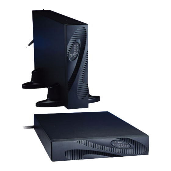
The PowerSure PSI comes in nominal power ratings of 1000, 1440, 2200, or 3000 VA. Refer to the Specifications section for details. The PowerSure PSI is a 2U, line-interactive UPS that may be installed in a rack or used in a tower configuration. A line-interactive UPS continuously conditions and regulates its output voltage, whether utility power is present or not. -
Page 11: Figure 2 1000 And 1440Va Psi-Rear View
Introduction Figure 2 1000 and 1440VA PSI—rear view Output Data Line Receptacles REPO Intellislot Port Connectors BATTERY CONNECTOR 1440VA/DC 48V/30A 1000VA/DC 48V/20A PHONE / FAX / MODEM / NETWORK PROTECTION LOAD 2 LOAD 1 INPUT INPUT BREAKER PUSH TO RESET INTELLISLOT External Battery Circuit Breaker... -
Page 12: Major Components
Major Components AJOR OMPONENTS Figure 5 Line diagram of PowerSure PSI 1000VA & 1440VA Input Output EMI/RFI Relay Filter Transformer Charger Battery Inverter Figure 6 Line diagram of PowerSure PSI 2200VA & 3000VA Input Output EMI/RFI Relay Filter Transformer DC-to-DC... -
Page 13: Automatic Voltage Regulator
- even if the UPS is turned Off. Battery The PowerSure PSI utilizes valve-regulated, nonspillable, lead acid batteries. To maintain battery design life, operate the UPS in an ambient temperature of 68°F to 77°F (20°C to 25°C). Optional external battery cabinets are available to extend battery run times. -
Page 14: What
What’s Included ’ NCLUDED The PowerSure PSI is shipped with the following items: • PowerSure PSI user manual • Warranty card • MultiLink software CD • MultiLink serial cable, 10 ft (3m) • USB cable, 6 ft (1.8m) • RJ-11 cord, 7 ft (2.1m) •... -
Page 15: Installation
UPS operation in temperatures above 77°F (25°C) reduces battery life. 3. The PowerSure PSI may be installed in either a tower configuration or in a rack, depending on available space and use considerations. Determine the type of installation and follow the appropriate instructions in either Tower UPS Installation or Rack-Mount UPS Conversion and Installation. -
Page 16: Rack-Mount Ups Conversion And Installation
Installation Rack-Mount UPS Conversion and Installation NOTE When rack mounted, the UPS must be supported by a shelf, slide rails, brackets or fixed rails on each side. The rack mount handles WILL NOT support the weight of the UPS. They are used to move the UPS into and out of the rack. -
Page 17: Figure 10 Rack Mounting Rails And Slide Assemblies
10. Use the extra M5 screws provided, secure front of the UPS to rack mounting rails to prevent the UPS from sliding out of position. 11. Plug the PowerSure PSI’s attached 10 ft. (3m) Vertical power cord into a dedicated wall receptacle... - Page 18 Serial communication via the RS232 is disabled. The USB, Intellislot, and Contact Closure com- munications operate in parallel. 15. REPO Switch—The PowerSure PSI is equipped with a Remote Emergency Power Off (REPO) switch. The user must supply a means of interfacing with the REPO circuit to allow disconnecting the UPS input feeder breaker to remove all sources of power to the UPS and connected equipment to comply with national and local wiring codes and regulations.
-
Page 19: External Battery Cabinet Installation
Ground External Battery Cabinet Installation Optional Liebert external battery cabinets may be connected to the UPS to provide additional battery run time. External battery cabinets are designed to be placed all on one side of the UPS or stacked beneath the UPS. The run time is limited to a maximum of four (4) hours. -
Page 20: Controls And Indicators
• After 24 hours, retest the batteries. • After the batteries have been retested, if all five (5) Battery indicators are not illuminated, con- tact your local dealer, Liebert representative or Liebert Worldwide Support Group. OFF Button When the UPS is on (in either Normal or Battery mode), pressing the OFF button for more... -
Page 21: Voltage Programming Button
The Battery Level Indicators are displayed in 20% increments as shown in Figure 13: Figure 13 Battery level indicators—5 green The PowerSure PSI is equipped with automatic and remote battery test features. The automatic test occurs every 14 days if utility has not been interrupted; this option may be configured by the user. -
Page 22: Over Temp Indicator-Amber
Controls and Indicators Over Temp Indicator—Amber The Over Temp Indicator flashes when the UPS detects an over temperature condition. This indicator illuminates when the UPS shuts down due to an over temperature condition (see Troubleshooting section for details). 6.10 Fault Indicator—Red The Fault Indicator illuminates when the UPS detects an internal problem (see Trouble- shooting section). -
Page 23: Modes Of Operation
The Automatic Voltage Regulator (AVR) circuitry compensates for fluctuations in utility power, such as voltage surges and sags. When the PowerSure PSI detects an abnormality, it raises the undervolt- age (boost) or lowers the overvoltage (buck) as needed. The AVR operates automatically and main- tains the output voltage to the connected critical equipment, without utilizing the batteries. -
Page 24: Battery Mode
Modes of Operation Battery Mode The UPS switches to Battery mode in the event of an extreme input voltage/frequency condition or complete utility failure. The battery system supplies power through the Inverter (1000VA & 1440VA) or through the DC-to-DC converter to the Bi-Directional Converter (2200VA & 3000VA) to generate power for the connected equipment. -
Page 25: Communications
Open Emitter Remote Shutdown Via the DB-9 Connector The PowerSure PSI can be shut down remotely by shorting Pins 5 and 6 or via Pins 4 and 5 of the DB-9 connector. 8.2.1 Any Mode Shutdown—Via Pins 5 & 6 When Pin 6 is shorted to Pin 5, the UPS output is shut Off regardless of what mode the UPS is oper- ating in. -
Page 26: Usb Interface Port
(www.liebert.com) or contact your local dealer or Liebert representative. Several option cards are available for use in the Intellislot port of the PowerSure PSI. The Intellislot OCWEBCARD provides SNMP and Web-based monitoring and control of the UPS across the network. -
Page 27: Voltage Programming Procedure
Voltage Programming Procedure OLTAGE ROGRAMMING ROCEDURE Figure 18 Load Level Indicators Load Level Indicators Voltage Programming Button 1. Remove the front bezel from the UPS. 2. UPS must be operating in Normal (AC) mode. NOTE Utility power will be applied to the connected load. 3. -
Page 28: Maintenance
Maintenance 10.0 M AINTENANCE The PowerSure PSI UPS requires very little maintenance. Follow these practices to prevent prob- lems. 10.1 Cleaning the UPS The following will help ensure trouble-free operation for years: • Vacuum dust from the ventilation intake occasionally. -
Page 29: 10.3.1 Internal Battery Replacement Procedure
6. Unpack the new battery assembly, taking care not to destroy the packing. Compare new and old battery assemblies to make sure they are the same. If so, proceed with Step 7; otherwise STOP and contact your local dealer, Liebert representative, or the Liebert Worldwide Support Group. 7. Slide in the new replacement battery pack. -
Page 30: Troubleshooting
Troubleshooting 11.0 T ROUBLESHOOTING The information below indicates various symptoms a user may encounter in the event the PowerSure PSI experiences a problem. Use this information to determine whether external factors caused the problem. See Table 2 - Troubleshooting chart for suggested remedy. 1. -
Page 31: Troubleshooting Chart
Check the circuit protector on the rear of the UPS. If it is tripped, reset it and restart the UPS. For Short circuit further help, contact your local dealer, Liebert representative or the Liebert Worldwide Support UPS will not start Group. -
Page 32: Specifications
Specifications 12.0 S PECIFICATIONS Table 3 UPS specifications PS1000RT2-120 PS1440RT2-120 PS2200RT2-120 PS3000RT2-120 Model Number Power Rating, VA/W 1000VA/750W 1440VA/1080W 2200VA/1650W 3000VA/2250W Dimensions, W x D x H, in (mm) 3.43 x 22 x 17 3.43 x 22 x 17 3.43 x 24.1 x 17 3.43 x 24.1 x 17 Unit (87 x 557 x 430) -
Page 33: Table 4 Battery Cabinet Specifications
Specifications Table 3 UPS specifications (continued) PS1000RT2-120 PS1440RT2-120 PS2200RT2-120 PS3000RT2-120 Model Number Agency Safety UL 1778, c-UL Listed ANSI C62.41, Category A, Level 3 Surge (IEEE 587, Category A); EN61000-4-5, Level 3, Criteria B EN61000-4-2, Level 3, Criteria B Susceptibility EN61000-4-3, Level 3, Criteria A Electrical Fast Transient EN61000-4-4, Level 4, Criteria A... -
Page 34: Table 5 Battery Run Times
Specifications Table 5 Battery run times Load% 1000VA 1440VA 2200VA 3000VA Internal Battery (minutes) 100% Internal Battery + 1 External Battery Cabinet (minutes) 100% 1001 — — Internal Battery + 2 External Battery Cabinet (minutes) 100% 1174 1001 — — 1001 —... -
Page 35: Product Warranty Registration
12.1 Product Warranty Registration To register for warranty protection, visit the Quick Links section of our Web site at: www.liebert.com Click on Product Warranty Registration and complete the form. If you have any questions, please contact us at: US: (800) 222-5877... - Page 36 Specifications...
- Page 38 The Company Behind the Products Technical Support/Service Web Site With over a million installations around the globe, www.liebert.com Liebert is the world leader in computer protection Monitoring systems. Since its founding in 1965, Liebert has 800-222-5877 developed a complete range of support and monitoring@liebert.com...
Need help?
Do you have a question about the PowerSure PSI and is the answer not in the manual?
Questions and answers