Rangemaster 110 Gas User's Manual & Installation Instructions
Hide thumbs
Also See for 110 Gas:
- User manual (36 pages) ,
- User's manual & installation instructions (36 pages) ,
- Installation and user manual (32 pages)

Subscribe to Our Youtube Channel
Related Manuals for Rangemaster 110 Gas


Summary of Contents for Rangemaster 110 Gas
-
Page 1: User Guide
Britain’s No.1 Range Cooker USER GUIDE & INSTALLATION INSTRUCTIONS Rangemaster 110 Gas... - Page 2 We o er cookware to work perfectly with all fuel types manufactured by Rangemaster, including induction hobs. You can be assured of functionality with style, as well as the quality and meticulous attention to detail you expect from the pioneers of range cooking.
-
Page 3: Table Of Contents
Tips on Cooking with the Timer Technical Data General Oven Tips Cooking Table Cleaning Your Cooker Essential Information Hotplate Burners The Griddle Grill Control Panel and Doors Glass Fronted Door Panels (some models) Ovens Cleaning Table Rangemaster 110 Gas U106140-08A... -
Page 5: Before You Start
1. Before You Start... Ventilation Thank you for buying this cooker. It should give you many years of trouble-free cooking if installed and operated CAUTION: The use of a gas cooking appliance results correctly. It is important that you read this section before you in the production of heat and moisture in the room start, particularly if you have not used a gas cooker before. -
Page 6: Cleaning
Cooking high moisture content foods Do not use water on grease res and never pick up a aming pan. Turn the controls o and then smother can create a ‘steam burst’ when the a aming pan on a surface unit by covering the pan oven door is opened. -
Page 7: Cooker Overview
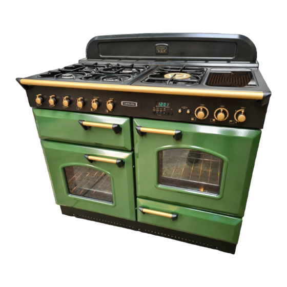
2. Cooker Overview DocNo.020-0006 - Overview - 90DF - Prof+ Fig.2-1 ArtNo.212-0002 - 110 Classic ceramic front view The 110 gas cooker (Fig.2-1) has the following features: Fig.2-2 Glass lid 5 hotplate burners including a warmer A control panel A grill... -
Page 8: Hotplate Burners
Hotplate Burners Fig.2-3 The drawing by each of the central knobs indicates which burner that knob controls. Each burner has a Flame Supervision Device (FSD) that prevents the ow of gas if the ame goes out. When the igniter button is pressed in, sparks will be made at every burner –... -
Page 9: The Griddle
The Griddle Fig.2-9 The griddle ts the left-hand pan support, front to back (Fig.2-9). It is designed for cooking food on directly. DO NOT use pans of any kind on it. The griddle surface is non-stick and metal cooking utensils (e.g. spatulas) will damage the surface. Use heat resistant plastic or wooden utensils. -
Page 10: The Grill
The Grill Fig.2-14 Before using the grill for the rst time turn on the grill and run for 30 minutes with the grill pan in position, pushed fully back, and the grill door open. Make sure the room is well ventilated to the outside ArtNo.330-0003 - Grill pan w handle pulled forwards air, by opening windows or turning on a cooker hood for example. -
Page 11: The Ovens
The Ovens ArtNo.323-0003 Bray gas oven burner flame Fig.2-18 The clock must be set to the time of day before the left- hand oven will work. See the following section on ‘The Clock’ for instructions on setting the time of day. References to ‘left-hand’... - Page 12 Whole poultry should not be cooked on ‘S’ . Chicken Fig.2-22 casseroles are ne. Casseroles must be brought to boiling point on the hotplate immediately before ‘S’ cooking. DO NOT stu poultry and rolled joints before cooking. The stu ng should be cooked separately. Poultry and pork should be cooked in the top half of the oven, and other meats not lower than shelf position 4.
-
Page 13: The Clock
The Clock Fig.2-24 You can use the timer to turn both ovens on and o . The clock must be set to the time of day before the ovens will work. Setting the Time of Day The 6-button LCD clock is shown in Fig.2-24. When the ArtNo.302-0002 - 6BC annotated clock is rst connected the display ashes ( 0.00 ) and (G) alternately. -
Page 14: Key Lock
AUTO is Showing, But You Want to Reset to Fig.2-34 Fig.2-35 Manual Cooking To return to manual cooking from any automatic setting, the ‘cook period’ must be cancelled. Press and hold the [E] button and then press the [ –] button until the display reads ArtNo.302-0009 - Activating ArtNo.302-0008 - the key lock 2... -
Page 15: Accessories
Accessories Fig.2-39 Oven Shelves Shelf guard The cooker is supplied with 4 at shelves (Fig.2-39). The oven shelves can be easily removed and re tted. Pull the shelf forward until the back of the shelf is stopped by the shelf stop bumps in the oven sides (Fig.2-40). Front Lift up the front of the shelf so the back of the shelf will pass under the shelf stop and then pull the shelf forward... -
Page 16: Main Oven Light
Main Oven Light Fig.2-46 Press the appropriate button to turn the light on (Fig.2-46). If an oven light fails, turn o the power supply before changing the bulb. See the ‘Troubleshooting’ section for ArtNo.320-0027 - Twin oven lights details on how to change the bulb. Storage The bottom drawer is for storing oven trays and other cooking utensils. -
Page 17: Cooking Tips
3. Cooking Tips Tips on Cooking with the Timer General Oven Tips If you want to cook more than one dish, choose dishes that The wire shelves should always be pushed rmly to the back require approximately the same cooking time. However, of the oven. -
Page 18: Cooking Table
4. Cooking Table The oven control settings and cooking times given in the table below are intended to be used AS A GUIDE ONLY. Individual tastes may require the temperature to be altered to provide a preferred result. ArtNo.050-0019 - Albertine SC - Shelf position Food is cooked at lower temperature in a fan oven than in a conventional oven. -
Page 19: Cleaning Your Cooker
5. Cleaning Your Cooker Essential Information Fig.5-1 Isolate the electricity supply before carrying out any thorough cleaning. Allow the cooker to cool. NEVER use paint solvents, washing soda, caustic cleaners, biological powders, bleach, chlorine based bleach cleaners, coarse abrasives or salt. DO NOT mix di erent cleaning products –... -
Page 20: The Griddle
The Griddle Fig.5-5 Always clean the griddle after use. Allow it to cool completely before removing. Immerse the griddle plate in hot soapy water. Use a soft cloth or, for stubborn stains, a nylon washing up brush. ArtNo.330-0003 - Grill pan w handle pulled forwards Note: If the griddle is washed in a dishwasher then some dishwasher residue may appear on the back. -
Page 21: Ovens
Ovens Fig.5-7 Thermostat temperature sensor Cleaning is easier if carried out while the oven is still warm. Before cleaning, cover the burner to prevent the burner holes becoming blocked. The inside of the oven and inner door panel can be cleaned using an approved cleaner (Table 5-1). -
Page 22: Cleaning Table
Cleaning Table Cleaners listed (Table 5-1) are available from supermarkets or electrical retailers as stated. For enamelled surfaces use a cleaner that is approved for use on vitreous enamel. Regular cleaning is recommended. For easier cleaning, wipe up any spillages immediately. Hotplate Part Finish... -
Page 23: Troubleshooting
6. Troubleshooting What cleaning materials are recommended for the The knobs get hot when I use the oven or the grill. Can I cooker? avoid this? See the ‘Cleaning’ section for recommended cleaning Yes, this is caused by heat rising from the oven or the materials. - Page 24 Oven not coming on Fig.6-1 Is the power on? Is the clock illuminated? If not, there may be something wrong with the power supply. Is the cooker supply on at the isolator switch? ArtNo.324-0005 Oven light bulb Has the time of day been set? Is the key symbol [F ...
-
Page 25: Installation
INSTALLATION Check the appliance is electrically safe and gas sound when you have nished. 7. Installation Dear Installer In the UK the cooker must be installed in accordance with: Before you start your installation, please complete the details below, so that, if your customer has a problem relating to All relevant British Standards / Codes of Practice, in your installation, they will be able to contact you easily. -
Page 26: Location Of Cooker
INSTALLATION Check the appliance is electrically safe and gas sound when you have nished. Checking the Parts: Location of Cooker The cooker may be installed in a kitchen/kitchen diner but 3 pan supports Griddle NOT in a room containing a bath or shower. This appliance is designed for domestic cooking only. -
Page 27: Positioning The Cooker
INSTALLATION Check the appliance is electrically safe and gas sound when you have nished. Positioning the Cooker Fig.7-1 Fig.7-1 shows the minimum recommended distance from the 75 mm 75 mm cooker to nearby surfaces. 650 mm The cooker should not be placed on a base. Above hotplate surround should be level with, or above, any adjacent work surface. -
Page 28: Completing The Move
INSTALLATION Check the appliance is electrically safe and gas sound when you have nished. cooker forward and remove the front half of the polystyrene Fig.7-6 base (Fig.7-5). Repeat from the back and remove the rear half of the polystyrene base. Lowering the Two Rear Rollers To adjust the height of the rear of the cooker, rst t a 13 mm spanner or socket wrench onto the hexagonal adjusting... -
Page 29: Levelling
INSTALLATION Check the appliance is electrically safe and gas sound when you have nished. Levelling Fig.7-11 Oven burner bracket You are recommended to use a spirit level on a shelf in one of the ovens to check for level. Place the cooker in its intended position taking care not to twist it within the gap between the kitchen units as damage may occur to the cooker or the units. -
Page 30: Electrical Connection
INSTALLATION Check the appliance is electrically safe and gas sound when you have nished. Pressure Testing Fig.7-13 Earth: to the The gas pressure can be measured at one of the hotplate terminal marked E, burner injectors (not the wok burner). coloured Green/Yellow Lift o a burner head. -
Page 31: Final Checks
INSTALLATION Check the appliance is electrically safe and gas sound when you have nished. Final Checks Fig.7-14 Hotplate Check Check each burner in turn (refer to the ‘Hotplate Burners’ section at the front of the instructions). Grill Check Turn on the grill and check that the grill heats up. Oven Check Set the clock as described earlier in the instructions, and then turn on the ovens. -
Page 32: Circuit Diagram
8. Circuit Diagram The connections shown in the circuit diagram are for single-phase. The ratings are for 230 V 50 Hz. Code Description Code Colour Code Description Right-hand oven thermostat switch Blue Clock Left-hand oven thermostat switch Brown Ignition switch Oven spark generator Hotplate &... -
Page 33: Technical Data
9. Technical Data DocNo.101-0010 - Technical data - 110 Gas - RM lidded This cooker is designed for use on either: • Natural gas (Cat I 2H ) at 20 mbar or • LP gas (Cat I 3+ ) Butane 29 mbar / Propane 37 mbar NOTE: The natural gas and LP gas versions of these cookers are di erent models and CANNOT be converted from one gas family to the other. - Page 34 Notes...
- Page 35 If you have any product enquiries, or in the event of a problem with your appliance once it has been installed, please For a competitive quote and to arrange for a Rangemaster approved telephone 0870 789 5107. engineer to attend, call Consumer Services on: 0870 789 5107.
- Page 36 Registered in England and Wales. Registration No. 354715 Registered O ce: Juno Drive, Leamington Spa, Warwickshire, CV31 3RG Rangemaster continuously seeks improvements in speci cation, design and production of products and thus, alterations take place periodically. Whilst every e ort is made to produce up-to-date literature, this booklet should not be regarded as an infallible guide to...
Need help?
Do you have a question about the 110 Gas and is the answer not in the manual?
Questions and answers
Hi, I have moved into a house that has an original 110 Range, electric. When I try to switch on the oven, it keeps switching off, showing the 'auto' sign. How do i operate the ovem manually without this happening.? Thankyou
To operate the Rangemaster 110 Gas oven manually when it keeps switching off and showing the 'AUTO' sign:
1. Cancel the automatic setting:
- Press and hold the [E] button.
- Press the [–] button until the display reads (0.00).
2. Return to manual cooking:
- Press the [B] button to switch back to manual operation.
This resets the oven to manual mode.
This answer is automatically generated