Datalogic Memor User Manual
Mobile computer
Hide thumbs
Also See for Memor:
- User manual (138 pages) ,
- Quick start manual (2 pages) ,
- Manual (2 pages)
Table of Contents
Advertisement
Quick Links
Download this manual
See also:
User Manual
Advertisement
Table of Contents

Related Manuals for Datalogic Memor


Summary of Contents for Datalogic Memor
- Page 1 Memor™ User’s Manual...
- Page 2 Software Version: 4.00 Ed.: 10/2011 © 2008-2011 Datalogic Mobile S.r.l. • All rights reserved. • Protected to the fullest extent under U.S. and international laws. • Copying, or altering of this document is prohibited without express written consent from Datalogic Mobile S.r.l.
-
Page 3: Table Of Contents
4.3.1 Laser Data Capture ................31 4.3.2 Imager Data Capture................. 32 Description of the Keys ..............34 4.4.1 Resetting the Memor ................. 36 Status Indicators ................39 4.5.1 LED Status ..................39 4.5.2 Taskbar ..................... 40 Data Capture Configuration............... 42 4.6.1... - Page 4 4.7.2 Registry ..................... 50 4.7.3 Files Admin ..................51 4.7.4 Wireless Communications..............53 4.7.5 Stylus Calibration ................55 4.7.6 Volume Settings ................58 Windows Connections............... 62 4.8.1 Microsoft® ActiveSync®..............62 4.8.2 Bluetooth® Manager Device Setup........... 64 4.8.3 Windows Mobile Phone..............73 4.8.4 FTP Server Setup................
-
Page 5: References
“Mobile computer” and "Memor" refer to Memor mobile computer. “You” refers to the System Administrator or Technical Support person using this manual to install, configure, operate, maintain or troubleshoot a Memor mobile computer. “Single Cradle” refers to the Memor Single Cradle. -
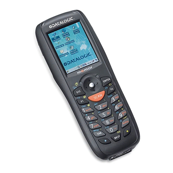
Page 6: General View
GENERAL VIEW QVGA 64K Color Display G) Microphone Good Read or User H) Strap with Stylus Holder Programmable LED I) Laser Safety Label Charging Status LED J) Rear Speaker Speaker K) ON/OFF Power Key Scan Key L) Product Label (under battery) Keyboard M) Battery Cover Data Capture/Laser Output... -
Page 7: Introduction
Java Virtual Machine. Memor provides voice and data wireless communication options to meet the business need. A speaker and microphone equip the Memor to handle - VoIP phone calls or push-to-talk conversations. The Summit IEEE 802.11 abg radio’s optimized transmit power and receiver sensitivity result in superior range with a tailored user interface for easy configuration and consistent management. -
Page 8: Models Description
Combined these tools streamline deployment and management activities while providing developer tools to further customize units for specific applications. MODELS DESCRIPTION The brand new Memor is available in different models depending on the options it is equipped with. All options are listed below: ... - Page 9 INTRODUCTION 944201041 DL-Memor+802.11+BT+2D+WM6.1 Memor, 802.11 abg CCX V4, Bluetooth, 128MB RAM/256MB Flash, 23-key Numeric, Std 2D Imager, WM 6.1...
-
Page 10: Package Contents
1 Windows Mobile/ CE End User License Agreement (depending on models) Any other packages will contain the accessories necessary for the Memor connection to the host computer and to the network: the cradle, one or more connection cables. Remove all the components from their packaging; check their integrity and congruity with the packing documents. -
Page 11: Inserting A Micro Sd Card
INTRODUCTION INSERTING A MICRO SD CARD Memor provides the possibility to add a Micro SD memory storage card. To access the Micro SD card slot and insert the card, proceed as follows: Turn off the Memor. Press the latch release button and pull the latch down, as indicated in... - Page 12 MEMOR™ Shift the cardholder to the left and then pull it up; insert the Micro SD card with the written part upward. Lock the card into place by pushing the cardholder down and then shifting it to the right; pull the locking plate down.
-
Page 13: Accessories
94A051016 CAB-421 USB Type A-B-Mini Straight 94A051022 WIN-NET Serial CAB (HRS ST40x-18S-CV) 94A051024 USB A (4 pin F) to Mini A (5 pin M) 94A051966 Cable Memor 12 TO 24 V Power Adapter Various 94ACC1328 DL-Memor Stylus Pen (10pcs) -
Page 14: Batteries And Maintenance
(see par. 4.5). If the battery pack is removed from the mobile computer, it can be recharged by inserting it into the rear slot of a Single Cradle or the Memor Multi Battery Charger. Do not use the Memor until batteries are charged for minimum 4 hours. - Page 15 Memor disconnected from power supply before the charging cycle is completed. NOTE The Memor could get warm during charging, this is normal and does not mean a malfunction. NOTE Use only a USB-IF compliant USB port as a charging source.
-
Page 16: Replacing The Battery Pack
MEMOR™ REPLACING THE BATTERY PACK To correctly replace the battery pack, proceed as follows. Turn off the Memor. Press the latch release button and pull the battery latch down as indicated in the figure below: Remove the cover and the battery pack. - Page 17 BATTERIES AND MAINTENANCE As the battery cover is lifted, the mobile computer automatically shuts off, in order to retain data during the pack substitution. CAUTION...
- Page 18 Using the battery pack in this manner may also result in a loss of performance and a shortened life expectancy. Use only a Datalogic Mobile approved power supply. The use of an alternative power supply will void the product warranty, may cause product damage and may cause heat, explode or ignite.
- Page 19 Memor does not turn on (when pressing the ON/OFF key). In this case, either substitute the battery pack with a charged one (sufficiently charged) or insert Memor into a NOTE powered cradle or plug it into the direct power supply.
-
Page 20: Cleaning The Mobile Computer
MEMOR™ CLEANING THE MOBILE COMPUTER Periodically clean the Memor with a slightly dampened cloth. -
Page 21: Connections
CONNECTIONS CONNECTIONS USB CONNECTION You can use any standard mini USB cable to directly connect the Memor to a host computer to transfer data through the USB interface. Key: Host Computer Memor Standard Mini USB cable Connection through the cable is compliant to 2.0 USB standard. - Page 22 MEMOR™ Connection through the cradle is compliant to 2.0 USB standard. NOTE The actual data transfer speed can be appreciably lower than the maximum theoretical speed. NOTE...
-
Page 23: Connection To Usb Peripherals
CONNECTION TO USB PERIPHERALS You can use a standard A (4 pin female) to mini A (5 pin male) USB cable to connect the Memor to a keyboard or a memory. For all these devices maximum current withdrawal must be below 100mA. - Page 24 MEMOR™ The actual data transfer speed can be appreciably lower than the maximum theoretical speed. NOTE...
-
Page 25: Rs232 Connection
CONNECTIONS RS232 CONNECTION You can use a cable to directly connect the Memor to a host computer to transfer data through the RS232 interface. Key: Host Computer Memor 94A051022 WIN-NET (HRS ST40X-18S-CV) The Single Cradle can be connected to the Host by any standard 9-pin serial null-modem cable for RS232 communications. -
Page 26: Wlan Connection
MEMOR™ WLAN CONNECTION Memor 802.11 abg radio models can communicate with the host using the on- board radio frequency component and an Access Point connected to the host computer. For models using the 802.11 abg radio, you can find information about the applet for radio configuration: http://www.summitdatacom.com/SCU.htm. - Page 27 Area coverage and radio performance may vary, due to environmental conditions, access points types or interference caused by other devices (microwave ovens, radio transmitters, etc.) NOTE In case of heavy usage the Memor could get warm, this is normal and does not mean a malfunction. NOTE...
-
Page 28: Wpan Connection
MEMOR™ WPAN CONNECTION Memor mobile computer models with Bluetooth can communicate with other Bluetooth enabled devices, such as a printer, within a range of 10 m, using the onboard Bluetooth module. Key: Memor Bluetooth printer In order to avoid wasting energy, the Bluetooth® module is off by default. -
Page 29: Connection Cables
CONNECTIONS CONNECTION CABLES RS232 Direct Connection: 94A051022 WIN-NET SERIAL CAB (HRS ST40x-18S-CV) Datalogic Memor™ HOST/PC side side 9-pin (female) Power Supply Polarity: VEXT... -
Page 30: Wireless And Radio Frequencies Warnings
WARNING Most modern electronic equipment is shielded from RF signals. However, certain electronic equipment may not be shielded against the RF signals generated by Memor. WARNING Datalogic recommends persons with pacemakers or other medical devices to follow the same recommendations provided by Health Industry Manufacturers Associations for mobile phones. - Page 31 CONNECTIONS An air bag inflates with great force. DO NOT place objects, including either installed or portable wireless equipment, in the area over the air bag or in the air bag deployment area. If vehicle’s wireless equipment is WARNING improperly installed and the air bag inflates, serious injury could result.
-
Page 32: Use And Functioning
STARTUP The Memor turns on when the battery pack or the external supply is inserted. After the battery pack is installed, use the [ON/OFF] key to turn the mobile computer on and off. - Page 33 USE AND FUNCTIONING The mobile computer can also be awakened or turned off by the application program. NOTE...
-
Page 34: Using The Stylus
On the pop-up menu that appears, tap hold: the action you want to perform. To recalibrate the touch screen use the Stylus Applet (see par. 4.7.5) Use only original Datalogic styluses supplied with the product itself. harsh applications,... -
Page 35: Using The Joystick
USE AND FUNCTIONING 4.1.2 Using the Joystick The joystick selects items and enters information. The joystick can work like the directional arrow keys of a PC keyboard or can function like a mouse and control the mouse pointer. It is possible to switch between the two functioning modes by pressing blue modifier + BKSP keys in sequence. -
Page 36: Windows Mobile Welcome Wizard
MEMOR™ WINDOWS MOBILE WELCOME WIZARD In Windows Mobile, at the very first Memor startup, following a clean boot or following a registry restore to default values, the mobile computer startup (see par. 4.1 is preceded by the Welcome Wizard. Welcome Wizard Screen The Welcome Wizard allows the user to calibrate the touch screen (see par. -
Page 37: Data Capture
4.3.1 Laser Data Capture To scan barcodes, point the Memor laser model onto the code from a distance within the reading range while pressing the SCAN key. The lighted band emitted by the laser must completely intercept the barcode as shown in the figure below. -
Page 38: Imager Data Capture
To read a 1D or 2D code, simply point the Memor Imager model onto the code and press the SCAN Key. The Memor Imager uses an intelligent aiming system pattern, similar to those... - Page 39 The field of view changes its size as you move the reader closer or farther away from the code. The field of view indicated by the aiming system pattern will be smaller when the Memor Imager is closer to the code and larger when it is farther from the code.
-
Page 40: Description Of The Keys
MEMOR™ DESCRIPTION OF THE KEYS The Memor provides a 23-key alphanumeric keyboard + ON/OFF key + joystick. The following image shows this keyboard. -
Page 41: Special Function Icons
Blue modifier: when pressed before a standard key, it enables the character or function printed in blue above the key. It powers the Memor ON or OFF. It is placed on the upper left side of the terminal. The ALPHA key is used to alternate numeric and alphanumeric use of the 10 numeric keys. -
Page 42: Resetting The Memor
To perform a warm boot, press these keys simultaneously: COLD BOOT A cold boot is a complete reset of the Memor in which all applications are forcibly closed and RAM is completely cleared. Registry is restored from persistent memory if a saved copy is available (see 4.7.2) and RAM file system completely erased. - Page 43 To perform a warm boot, press and hold the following keys simultaneously: Cold Boot A cold boot is a complete reset of the Memor in which all applications are forcibly closed and the RAM is completely cleared. Registry is restored from persistent memory if a saved copy is available (see Registry Applet, par.
- Page 44 A clean boot is a cold boot that causes the device to be restored to a clean configuration. The Memor will be reset to its factory configuration only if the user has not installed any additional package. Please note that you will lose any applications and data stored in persistent flash memory.
-
Page 45: Status Indicators
USE AND FUNCTIONING STATUS INDICATORS 4.5.1 LED Status The Memor provides two different LEDs signaling the mobile computer status. STATUS Good Read and Green It is constant for a configurable time General Purpose to signal that a successful read has (left side) occurred. -
Page 46: Taskbar
MEMOR™ 4.5.2 Taskbar The Taskbar provides information about the time, the battery level, the keyboard function, and the decoding status. ICONS DESCRIPTION Time and Battery Icons It displays the time. In Windows CE, they are representative of five different icons indicating the battery level. The icon is partially green when the power left is >20% and partially red... - Page 47 USE AND FUNCTIONING Windows CE Taskbar Windows Mobile Taskbars...
-
Page 48: Data Capture Configuration
MEMOR™ DATA CAPTURE CONFIGURATION From the Windows CE Taskbar, tap the "Decoding" icon to open a drop–down menu. Decoding can also be accessed from the Control Panel. By selecting the Info item from this drop-down menu you can access information about the Scanner and the Software;... - Page 49 USE AND FUNCTIONING Data Capture Configuration Window The screen format shows two columns where the left column indicates branches or parameters. Branches have three dots in the right column (...). You can navigate through the tree structure using the stylus or keyboard arrows directly on the item field or from the menu.
-
Page 50: Reader Parameters
MEMOR™ Reader Parameters The barcode reading parameters and values are dependent upon the type of scanner module mounted in your mobile computer. For a detailed list of parameters and of their configuration procedures, please refer to the SDK Help file on the CD. -
Page 51: Default Settings
USE AND FUNCTIONING Default Settings The following tables contain the default values for the major barcode setup parameters, according to the type of scan engine mounted on the mobile computer. For a complete list of parameters and of their configuration procedures, please refer to the SDK Help file on the CD. - Page 52 MEMOR™ BARCODE SYMBOLOGY IMAGER LASER MODELS SPECIFIC READER PARAMETERS MODELS Disabled Not available Plessey Disabled Not available Disabled Enabled Code 93 Disabled Not available Code 11 GS1 Databar Disabled Enabled Disabled Not available GS1 Databar Omnidirectional Not available Enabled GS1 Databar General...
-
Page 53: Capture
USE AND FUNCTIONING 4.6.2 Capture The Data Capture applet (Capture) enables code reading. Data Capture Window Data Capture can also be enabled through the Configuration applet by selecting File ->Scanner from the main menu, or by enabling the parameter Scan Always On in the Scan Parameters branch. -
Page 54: Control Panel
MEMOR™ CONTROL PANEL From the Windows CE Desktop, double tap on the "My Device" icon and then double tap on the "Control Panel" icon to open the Windows CE control panel main window. The Control Panel can also be launched from Start ->Settings - >Control Panel. -
Page 55: Buttons
USE AND FUNCTIONING 4.7.1 Buttons To configure the way up/down and the rest of keys control repeats, use the Up/Down Control applet (Start -> Settings -> Personal -> Buttons -> Up/Down Control). Windows CE Buttons Icon Windows Mobile Buttons Icon You can also select to wake up the terminal by the SCAN key. -
Page 56: Registry
MEMOR™ 4.7.2 Registry The REGISTRY ADMIN applet provides management of Windows CE 5.0/ Windows Mobile registry. From the Windows CE control panel main window, select the REGISTRY ADMIN applet by double tapping the Registry Admin icon. From the Windows Mobile Start menu, tap Settings -> System ->Registry Admin. -
Page 57: Files Admin
USE AND FUNCTIONING 4.7.3 Files Admin The FILES ADMIN applet enables control of the permanence of files in the Windows CE System Folder. Because Windows Mobile mounts the entire file system in persistent store (rather than using RAM), it provides both users and applications with a reliable storage platform even in the absence of battery power. - Page 58 MEMOR™ Select an installation file (for example, a .CAB cabinet file) from the Safe Setup mask. Safe Setup First Mask Then select \Windows or a relevant sub-directory in the path box. Then, Safe Setup will recognize the new files and directories present in the \Windows directory, and will copy them to the \Backup\Windows directory.
-
Page 59: Wireless Communications
USE AND FUNCTIONING 4.7.4 Wireless Communications The WIRELESS COMMUNICATIONS applet provides management of the 802.11 abg radio, the Bluetooth modules. Windows CE Wireless Communications Windows Mobile Connectivity Icon Icon If the mobile computer supports Windows CE, select the WIRELESS COMMUNICATIONS applet by double tapping the Wireless Communications icon. - Page 60 MEMOR™ Windows Mobile Wireless Communications Window...
-
Page 61: Stylus Calibration
USE AND FUNCTIONING 4.7.5 Stylus Calibration You might need to recalibrate the touch screen (i.e. when you attempt to select one item with the stylus, another item is erroneously selected). To recalibrate the touch screen on Windows CE, complete the following steps: Select Start >... - Page 62 MEMOR™ Figure 2 To recalibrate the touch screen on Windows Mobile, complete the following steps: Select Start > Settings > System > Screen to open the Screen Settings dialog as shown in Figure 3. Figure 3 Tap Align Screen to open the Calibration screen shown in Figure 4.
- Page 63 USE AND FUNCTIONING Figure 4 Startup stylus calibration on Windows CE When starting the terminal, a stylus calibration screen comes up if valid calibration settings are not available. This happens in the following circumstances: At the first startup of the terminal. After restoring registry default settings using the applet Registry Admin and performing a warm boot.
-
Page 64: Volume Settings
MEMOR™ 4.7.6 Volume Settings Windows CE From the Windows CE control panel main window, select the Audio applet by double tapping the ‘Audio’ icon: The Audio applet allows to set the recording volumes of the main microphone and of the headset microphone. Also, it allows to set the headset volume when the user is listening to an audio file. - Page 65 USE AND FUNCTIONING From the Windows CE control panel main window, select the Volume & Sounds applet by double tapping the Volume & Sounds icon: The Volume & Sounds applet allows to manage the audio features of the rear speaker and appears as follows: Volume &...
- Page 66 MEMOR™ Windows Mobile From the Windows Mobile Start Menu, select Settings > Connections tab and click the Audio icon: Audio Window The Audio applet allows to set the recording volumes of the main microphone and of the headset microphone. Also, it allows to set the headset volume when...
- Page 67 USE AND FUNCTIONING To set the speaker volume during a call, click the icon on the right top of the Windows Mobile Start Menu. To set the front speaker or the headset speaker volume, use the right bar or move the joystick up and down. To set the rear speaker volume, use the left bar.
-
Page 68: Windows Connections
MEMOR™ WINDOWS CONNECTIONS To connect the Memor to another device (i.e. Host PC) from Windows, several programs are available. These programs require specific electrical connections in order to function properly. 4.8.1 Microsoft® ActiveSync® ® ® Microsoft ActiveSync gives you the possibility to connect your desktop computer to your Memor and synchronize the information on them. -
Page 69: Activesync® Remote
USE AND FUNCTIONING Visit the following Microsoft Web site for the latest in updates and technical information: http://www.microsoft.com/windowsmobile/activesync/default.mspx NOTE ActiveSync® Remote Microsoft® ActiveSync Remote is no longer supported in ® Windows CE. For backward compatibility you can download it from the Internet. We suggest enabling the FTP Server and connecting to an FTP Client. -
Page 70: Bluetooth® Manager Device Setup
Bluetooth radio and specify settings for Incoming Connections. Select or clear the “Enable Bluetooth Radio” check box: Tap Find Me if you want to make the Memor visible to other Bluetooth devices for 60 seconds, allowing them to set up a connection. - Page 71 Connections tab > Bluetooth Manager. Search for the type of Device(s) you want to connect to by tapping Printer, Serial or All. The Memor will search for Bluetooth® Devices within range. If you attempt to set up a connection when the Bluetooth®...
- Page 72 MEMOR™ To set up a connection: From the list of available devices, double tap the one you want to activate, or select and then tap Connect. The resulting dialog will display services that are available on the device: Select the service you want to connect to. The following table shows the icons that display for different types of service.
- Page 73 USE AND FUNCTIONING Tap OK to complete. The dialog will also appear when an Authentication request is received from another device. Once you have set up a Pairing, you can view the settings by double-tapping its name from the Connections tab. The Pairing info dialog will display different options, depending on what type of device you have selected and what service you use.
- Page 74 MEMOR™ The icons displayed in the taskbar at the bottom of your Memor ’s screen will show you the state of the Bluetooth connection, as shown in the table below. Name Icon Description Disabled Icon Indicates that Bluetooth has been disabled.
- Page 75 Bluetooth radio and specify settings for Incoming Connections. Select or clear the “Enable Bluetooth Radio” check box: Tap Find Me if you want to make the Memor visible to other Bluetooth devices for 60 seconds, allowing them to set up a connection.
- Page 76 Search for available Bluetooth® Devices by tapping the button for the type of device you want (Printer, Serial or All) or tap Discovery to skip this step. The Memor will search for Bluetooth® Devices within range. If you attempt to set up a connection when the Bluetooth®...
- Page 77 USE AND FUNCTIONING To set up a connection: Double tap the device you want to activate, or select and then tap Connect. The resulting dialog will display services that are available on the device:...
- Page 78 MEMOR™ Select the service you want to connect to. The following table shows the icons that display for different types of service. Icon Service Dialup Networking Printer File Transfer Protocol (FTP) Object Exchange (OBEX) Object Push (OPP) Object Exchange (OBEX)
-
Page 79: Windows Mobile Phone
USE AND FUNCTIONING Tap OK to complete. The dialog will also appear when an Authentication request is received from another device. Once you have set up a Pairing, you can view the settings by double-tapping its name from the Connections tab. Tap the arrow to change the Virtual Port, or Delete to remove the device pairing. -
Page 80: Ftp Server Setup
Protocol (FTP) server. FTP is used for copying files to and from remote computer systems over a network using TCP/IP. You can establish a connection to your Memor using its FTP Server through the following interfaces: WLAN using the 802.11 abg radio Proceed as follows: Create a registry file (extension .reg) to setup and enable FTP Server... -
Page 81: Backup Directory File Management
Even if the entire Windows Mobile file system reside in FLASH (non-volatile memory), the mechanism described above is supported also on Windows Mobile for backward compatibility. 4.10 FIRMWARE UPDATE The Memor is equipped with a tool that implements a firmware update service. For further information, refer to DFU Reference Guide. -
Page 82: Technical Features
MEMOR™ TECHNICAL FEATURES TECHNICAL DATA Memor Common Features PHYSICAL CHARACTERISTICS DIMENSIONS (LXWXH) 15.2 x 5.5 x 4.0 cm / 5.9 x 2.2 x 1.6 in WEIGHT 220 g / 7.76 oz (incl. 1100 mAH battery) (DEPENDING ON MODEL) 250 g / 8.81 oz (incl. 2000 mAH battery) - Page 83 TECHNICAL FEATURES SYSTEM Windows CE 5.0 Professional/ Windows OPERATING SYSTEM Mobile 6.1 Professional ™ MICROPROCESSOR Marvell XScale PXA 310 624 MHz SYSTEM RAM MEMORY 128 MB SYSTEM FLASH MEMORY 256 MB POWER SUPPLY DC Supply 5 V ± 5% 1 cell Li-Pol or Li-Ion 1100 mAh@3.7 V (nominal) Battery Pack Alternatively 1 cell Li-Pol or Li-Ion 2000...
- Page 84 MEMOR™ READING OPTIONS LASER CHARACTERISTICS SCANNING RATE - BIDIRECTIONAL 104 ± 12 scan/sec MAXIMUM RESOLUTION 0.10 mm / 4 mils SKEW ANGLE ± 50° PITCH ANGLE ± 65° AIMING LASER VLD, wavelength 630~680 nm UPC A, UPC E, EAN 8, EAN 13,...
- Page 85 TECHNICAL FEATURES Laser: Class 2 LASER CLASSIFICATION Safety class: N 60825-1:2001 LED CLASSIFICATION Led (Illuminator): Class 1M ILLUMINATION SYSTEM LEDs 620~630 nm...
-
Page 86: Reading Diagrams
MEMOR™ READING DIAGRAMS Memor 1D Typical Reading Diagram - Reading Zones (10° skew angle) 1,00 mm (40 mils) 0,35 mm 1,4 mm 0,50 mm (14 mils) (55 mils) (20 mils) 0,25 mm (10 mils) 0,19 mm (7,5 mils) 0,13 mm... - Page 87 TECHNICAL FEATURES Memor SE4500-DL Typical Reading Diagram - Reading Zones (10° skew angle) 13 mil 20 mil UPC-A Code 39 10 mil 15 mil 6.67 mil PDF417 PDF417 PDF417 5.0 mil 7.5 mil PDF417 Code 39 5.0 mil Code 39...
-
Page 88: Test Codes
MEMOR™ TEST CODES High Density Codes 0.25 mm (10 mils) !17162H! Code 39 17162 Ë"8NduÌ 2/5 Interleaved 0123456784 ÌtestwÎ Code 128 test x(0B2DE5*KKKKLM( EAN 13 (6450*TRMN( EAN 8... - Page 89 TEST CODES Medium Density Codes 0.38 mm (15 mils) !17162H! Code 39 17162 Ë"8NduÌ Interleaved 2/5 0123456784 ÌtestwÎ Code 128 test 100% x(0B2DE5*KKKKLM( EAN 13 100% (6450*TRMN( EAN 8...
- Page 90 MEMOR™ Low Density Codes 0.50 mm (20 mils) !17162H! Code 39 17162 Ë"8NduÌ Interleaved 2/5 0123456784 ÌtestwÎ Code 128 test 120% x(0B2DE5*KKKKLM( EAN 13 120% (6450*TRMN( EAN 8...
- Page 91 TEST CODES 2D Codes Datamatrix ECC200 Example Inverse Datamatrix ECC200 Example...
-
Page 92: Safety Regulations
Memor or else be supplied by a UL Listed/CSA Certified Power Unit marked “Class 2” or LPS power source rated 5 V, 3.0 A, which supplies power directly to the Memor via the power connector of the cable. -
Page 93: Laser Safety
LASER SAFETY The laser light is visible to the human eye and is emitted from the window indicated in the figure. This information applies to both laser models and the Memor Imager Aiming System. Laser output window... - Page 94 La luce laser è Die Laserstrahlung Le rayon laser est La luz láser es visibile all'occhio ist für das visible à l'oeil nu et il visible al ojo umano e viene menschliche Auge est émis par la humano y es emessa dalla sichtbar und wird am fenêtre désignée sur...
- Page 95 ENGLISH The following information is provided to comply with the rules imposed by international authorities and refers to the correct use of your mobile computer. STANDARD LASER SAFETY REGULATIONS This product conforms to the applicable requirements of both CDRH 21 CFR 1040 Subchapter J and EN 60825-1:2001 at the date of manufacture.
- Page 96 Non tentare di accedere allo scomparto contenete i componenti ottici o di farne la manutenzione. L’apertura dello scomparto, o la manutenzione di qualsiasi parte ottica da parte di personale non ATTENZIONE autorizzato, potrebbe violare le norme della sicurezza. Il sistema ottico può essere riparato solamente alla fabbrica.
- Page 97 Jegliche Änderungen am Gerät sowie Vorgehensweisen, die nicht in dieser Betriebsanleitung beschrieben werden, können ein gefährliches Laserlicht verursachen. ACHTUNG Der Produkt benutzt eine Laserdiode. Obwohl zur Zeit keine Augenschäden von kurzen Einstrahlungen bekannt sind, sollten Sie es vermeiden für längere Zeit in den Laserstrahl zu schauen, genauso wenig wie in starke Lichtquellen (z.B.
- Page 98 L’utilisation d’instruments optiques avec le scanneur augmente le danger pour les yeux. Les instruments optiques comprennent les jumelles, les microscopes, les lunettes et les verres grossissants. ATTENTION ESPAÑOL Las informaciones siguientes son presentadas en conformidad con las disposiciones de las autoridades internacionales y se refieren al uso correcto del terminal.
-
Page 99: Led Class
LED CLASS According to EN60825-1:2001, the Memor 1D models which use the green spot LED are also CLASS 1 LED PRODUCTS. APPARECCHIO LED CLASSE 1 IEC PRODUIT LED DE CLASSE 1 IEC PRODUKT LED KLASSE 1 IEC PRODUCTO LED DE CLASE 1 IEC According to EN60825-1:2001, the Memor 2D models which use the illuminator LED are also CLASS 1M LED PRODUCTS. - Page 100 Information for the User ENGLISH Contact the competent authority responsible for the management of radio frequency devices of your country to verify any possible restrictions or licenses required. Refer to the web site http://europa.eu.int/comm/enterprise/rtte/spectr.htm further information. ITALIANO Prendi contatto con l'autorità competente per la gestione degli apparati a radio frequenza del tuo paese, per verificare eventuali restrizioni o licenze.
-
Page 101: Fcc Compliance
FCC COMPLIANCE FCC Regulations: This device complies with part 15 of the FCC Rules. Operation is subject to the following two conditions: (1) This device may not cause harmful interference, and (2) this device must accept any interference received, including interference that may cause undesired operation. -
Page 102: Rf Exposure Information (Sar)
The highest SAR value for the model device as reported to the FCC are the following: DL-Memor + 802.11 + BT models: for use at the head is 1.32 W/Kg and when worn on the body, as described in the user guide, is 0.518 W/Kg. -
Page 103: Industry Canada Compliance
INDUSTRY CANADA COMPLIANCE Operation is subject to the following two conditions: (1) this device may not cause interference, and (2) this device must accept any interference, including interference that may cause undesired operation of the device. This Class B digital apparatus complies with Canadian ICES-003. Cet appareil numérique de la classe B est conforme à... -
Page 104: Sar Compliance
SAR COMPLIANCE This product has been tested and found to comply with the following standards: OET BULLETIN 65 SUPPLEMENT C: evaluating compliance with FCC guidelines for human exposure to radio frequency electromagnetic fields. EN 62311:2008: assessment of electronic and electrical equipment related to human exposure restrictions for electromagnetic fields (0 Hz –... -
Page 105: Weee Compliance
Per maggiori dettagli sulle modalità di smaltimento, contattare il Fornitore dal quale è stata acquistata l’apparecchiatura o consultare la sezione dedicata sul sito www.mobile.datalogic.com. Information for the user in accordance with the European Commission Directive 2002/96/EC At the end of its useful life, the product marked with the crossed out wheeled wastebin must be disposed of separately from urban waste. - Page 106 Pour obtenir des informations complémentaires concernant l'élimination, veuillez contacter le fournisseur auprès duquel vous avez acheté le produit ou consulter la section consacrée au site Web www.mobile.datalogic.com. Información para el usuario de accuerdo con la Directiva Europea 2002/96/CE Al final de su vida útil, el producto marcado con un simbolo de contenedor de...
-
Page 107: China Rohs Pollution Control Logos
CHINA ROHS POLLUTION CONTROL LOGOS Toxic or Hazardous Substances and Elements for DL-MEMOR Part name Cr6+ PBDE Upper Case Lower Case Touch Panel Board Laser Engine Imager Engine BT Module (Note 1) 802.11 a/b/g Radio Module (Note 1) 99% of the parts of this product adopt the nonpoisonous and harmless... -
Page 108: Glossary
GLOSSARY Access Point A device that provides transparent access between Ethernet wired networks and IEEE 802.11 interoperable radio-equipped mobile units. Hand-held mobile computers, PDAs or other devices equipped with radio cards, communicate with wired networks using Access Points (AP). The mobile unit (mobile computer) may roam among the APs in the same subnet while maintaining a continuous, seamless connection to the wired network. - Page 109 gradual on each side of the focused distance, so that within the DOF, the unsharpness is imperceptible under normal viewing conditions. EEPROM Electrically Erasable Programmable Read-Only Memory. An on-board non- volatile memory chip. Ethernet The standard local area network (LAN) access method. A reference to "LAN," "LAN connection"...
- Page 110 Pairing A Bluetooth pairing occurs when two Bluetooth devices agree to communicate with each other and establish a connection. Piconet A piconet is a Bluetooth PAN that links up to eight devices. Each piconet is controlled by one master device, and up to seven slave devices at any one time. Any device may be a member of more than one piconet, changing its membership as a user moves from one area to another.
- Page 111 which the connections are wireless. Typically, a wireless personal area network uses some technology that permits communication within about 10 meters - in other words, a very short range.
-
Page 112: Index
Conventions; v Reference Documentation; v References; v Registry; 50 Replacing the Batteries; 10 Data Capture; 31 Resetting the Memor; 36 Imager Data Capture; 32 RF Exposure Information (SAR); Laser Data Capture; 31 Data Capture Configuration; 42 RS232 Connection; 19 Default Settings; 45 Description of the Keys;... - Page 113 Technical Features; 76 Test Codes; 82 WEEE Compliance; 99 Windows Connections; 62 Windows Mobile Bluetooth® Manager Device Setup; 69 USB Connection; 15 Windows Mobile Phone; 73 Using the Joystick; 29 Windows Mobile Welcome Wizard; Using the Stylus; 28 Wireless and Radio Frequencies Warnings;...
- Page 114 Datalogic Mobile S.r.l. Via S. Vitalino, 13 40012 - Lippo di Calderara Bologna - Italy dichiara che declares that the déclare que le bescheinigt, daß das Gerät declare que el modelli con funzionalità radio 802.11abg+BT DL-MEMOR models with 802.11abg+BT radio feature modèles avec 802.11abg+BT radio intégrés...
- Page 115 EN 60950-1:2006 + A11:200 : INFORMATION TECHNOLOGY EQUIPMENT AFETY ENERAL EQUIREMENTS EN 62311:2008 : SSESSMENT OF ELECTRONIC AND ELECTRICAL EQUIPMENT RELATED HUMAN EXPOSURE RESTRICTIONS (0 H - 300 GH ELECTROMAGNETIC FIELDS Lippo di Calderara, July 11th 2011 Paola Chientaroli Quality Assurance Manager...
- Page 116 World wide Sales Network available from: www.mobile.datalogic.com/contacts Datalogic Mobile S.r.l. Via S. Vitalino, 13 40012 Lippo di Calderara di Reno Bologna - Italy Telephone: (+39) 051-3147011 Fax: (+39) 051-3147561 822000891 (Rev. A) ©2008-2011 Datalogic Mobile S.r.l. 10/11...
Need help?
Do you have a question about the Memor and is the answer not in the manual?
Questions and answers