Table of Contents
Advertisement
Advertisement
Table of Contents

Related Manuals for TMC AI5TV


Summary of Contents for TMC AI5TV
- Page 1 AI5TV User's Manual Version 1.3D...
-
Page 2: Table Of Contents
J7: Power Supply Connector ............17 I/O Connector ................18 J14: Front Bezel Connector ............18 J21: CPU Fan Power Connector ........... 18 J20: IR Connector ............... 19 J27, J28: USB Connector ............. 19 Chapter 5 BIOS ............20 AI5TV Motherboard User’s Manual... -
Page 3: Chapter 1 Specifications
Chapter 1 Specifications Chapter 1 Specifications The AI5TV is a high performance PCI system board. It's highly flexible in CPU frequency, L2 cache type and size, and main memory type and size. The main features are listed as follows: Main Processor... -
Page 4: Expansion Slots
Three ISA slots* * One shared slot Onboard I/O Winbond 877 Supper I/O for two serial ports (16550 UART compatible) and one parallel port (ECP/EPP compatible) and one floppy interface that support up to 2.88MB floppy drives. AI5TV Motherboard User’s Manual... -
Page 5: Chapter 2 Hardware Description
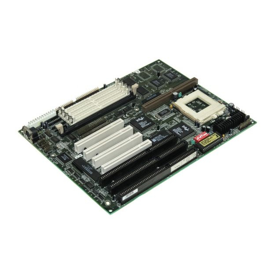
Chapter 2 Hardware Description Chapter 2 Hardware Description This chapter briefly describes each of the major features of the AI5TV system board. The layout of the board is shown in Figure 1 which shows the locations of key components. The topics covered in this chapter are as follows: 2.1 Processor... - Page 6 Chapter 2 Hardware Description Figure 1: Layout of the AI5TV AI5TV Motherboard User’s Manual...
-
Page 7: Processor
Chapter 2 Hardware Description 2.1 Processor The AI5TV is designed to take a Pentium processor with a bus speed of 50, 60 and 66 MHz. Since the internal clock of the CPU can be multiples of 1.5, 2, 2.5 or 3 of the bus clock, the CPU frequency can be 75MHz to 200MHz. -
Page 8: Main Memory
Chapter 2 Hardware Description 2.3 Main Memory The AI5TV provides two 64-bit memory banks for up to 128MB. Each bank consist of two SIMM sockets, M0/M1 and M2/M3. Both EDO and page mode DRAMs are supported. The size of the SIMMs can be 4MB, 8MB, 16MB or 32MB. -
Page 9: Bios
64MB 64MB 2.4 BIOS The BIOS on the AI5TV system board provides the standard BIOS functions plus the following additional features: 1. ISA Plug and Play (PnP) extension Unlike PCI cards which are plug and play, ISA cards require setting jumpers to resolve hardware conflict. -
Page 10: I/O Port Address Map
2.6 DMA Channels There are seven DMA Channels available on the system board. Only DRQ2 is used by the floppy controller. In the case that ECP mode on parallel port is used, DRQ1 or DRQ3 will be used. AI5TV Motherboard User’s Manual... -
Page 11: Interrupt Request
16550 UART compatible. The parallel port supports high speed EPP/ECP mode. The floppy controller supports up to 2.88 MB format. The I/O port addresses of the serial and parallel ports are programmable via BIOS set-up. Each I/O can be individually disabled. AI5TV Motherboard User’s Manual... -
Page 12: Sw1: At Bus Clock Speed Select
Chapter 3 Configuring the AI5TV Chapter 3 Configuring the AI5TV The following sections describe the necessary procedures and proper jumper settings to configure the AI5TV motherboard. SW1: AT Bus Clock Speed Select Page 12 SW2: P54C/P55C Type Select Page 12... - Page 13 Chapter 3 Configuring the AI5TV Figure 2: Jumper Location of the AI5TV AI5TV Motherboard User’s Manual...
-
Page 14: Sw3, Sw5, Sw6, Sw7, Sw8: Cpu Frequency Select
Chapter 3 Configuring the AI5TV SW1: AT Bus Clock Select Use this DIP-Switch to select the frequency of the AT bus clock (ATCLK). The ATCLK is derived from the PCI clock (PCLK) as PCLK/3 or PCLK/4 and the PCLK is derived from the CPU clock (CLK) as CLK/2. - Page 15 Chapter 3 Configuring the AI5TV For Cyrix 6x86, 6x86L CPUs SW3 SW5 SW6 SW7 SW8 Clock Multiplier 50MHz 6x86-P120+ (100MHz) 55MHz 6x86-P133+ (110MHz) 60MHz 6x86-P150+ (120MHz) 66MHz 6x86-P166+ (133MHz) For AMD K5/K6 CPUs SW3 SW5 SW6 SW7 SW8 Bus Clock Multiplier...
-
Page 16: Chapter 4 Installation
Chapter 4 Installation Chapter 4 Installation This chapter describes the connectors and interface that the AI5TV provides for creating a working system. Refer to Figure 3 for the location of the connectors. The following items are covered in this chapter:... - Page 17 Chapter 4 Installation Figure 3: Connector Location of the AI5TV AI5TV Motherboard User’s Manual...
- Page 18 N.C. Grou J4: PS/2 Mouse Connector The PS/2 mouse connector of the AI5TV motherboard is a 10-pin header for the optional PS/2 mouse external connector. The following table shows the pin out assignments of this connector. Signal Name Pin # Pin # Signal Name N.C.
- Page 19 Chapter 4 Installation AI5TV Motherboard User’s Manual...
- Page 20 ADJACENT to each other. That is, black wires of each connector should be aligned in the center of the power supply connectors, J7, of the AI5TV. The following table indicates the pin-out assignments of the power supply connectors.
- Page 21 Chapter 4 Installation I/O Connector The I/O connectors connect the AI5TV to the most common peripherals. To connect cables to these connectors, align carefully the Pin 1 of the cables to that of connectors. Refer to Figure 3 for the location and orientation of the connectors.
- Page 22 Chapter 4 Installation J21: FAN This J21 is an easy access connector for CPU fan power. The fan must be a 12V fan. AI5TV Motherboard User’s Manual...
-
Page 23: J27, J28: Usb Connector
J27 and J28 are pin headers for the optional USB external connector. The following table shows the pin out assignments of these connectors. J27 (USB1) J28 (USB2) Signal J27 1 1 J28 Name Pin # Pin # 4 USB USB- USB+ Ground AI5TV Motherboard User’s Manual... -
Page 24: Chapter 5 Bios
<PgUp> and <PgDn> keys to change entries, <F1> for help and <Esc> to quit. When you enter the Setup utility, the Main Menu screen will appear on the screen. The Main Menu allows you to select from various setup functions and exit choices. AI5TV Motherboard User’s Manual... -
Page 25: Standard Cmos Setup
You will need to run the Standard CMOS option, however, if you change your system hardware configurations, onboard battery fails, configurations stored in the CMOS memory were lost or damaged. AI5TV Motherboard User’s Manual... - Page 26 Hour : 00 to 23 Minute : 00 to 59 Second : 00 to 59 To set the time, highlight the “Time” field and use the <PgUp>/ <PgDn> or +/- keys to set the current time. AI5TV Motherboard User’s Manual...
- Page 27 The hard disk will not work properly if you enter improper information in these fields. If your hard disk drive type is not matched or listed, you can use Type User to define your own drive type manually. AI5TV Motherboard User’s Manual...
- Page 28 The system boot will not be halted for a disk error; it will stop for all other errors. All, But Disk/Key The system boot will not be halted for a keyboard or disk error; it will stop for all other errors. AI5TV Motherboard User’s Manual...
-
Page 29: Bios Features Setup
If you will run such a program, disable the Virus Warning feature. CPU Internal Cache / External Cache These items allow you to enable (speed up memory access) or disable the cache function. By default, these items are Enabled. AI5TV Motherboard User’s Manual... - Page 30 Typematic Rate Setting When disabled, continually holding down a key on your keyboard will generate only one instance. When enabled, you can set the two typematic controls listed next. By default, this field is set to Disabled. AI5TV Motherboard User’s Manual...
- Page 31 RAM. Video Shadow will increase the video speed. C8000 - CBFFF Shadow/DC000 - DFFFF Shadow Shadowing a ROM reduces the memory available between 640KB to 1024KB. These fields determine whether optional ROM will be copied to RAM or not. AI5TV Motherboard User’s Manual...
-
Page 32: Chipset Features Setup
If refreshed time is not enough, refresh may be incomplete and data will be lost. DRAM R/W Leadoff Timing This field allows you to set the number of CPU clocks before reads and writes to DRAM. By default, it is set to 7/6 Leadoff timing. AI5TV Motherboard User’s Manual... - Page 33 16MB. By default, this field is set to Disabled. Peer Concurrency This field allows you to select the number of PCI devices to be activated at a time. The default value is Enabled. AI5TV Motherboard User’s Manual...
-
Page 34: Power Management Setup
This field allows you to use Advanced Power Management device to enhance the Max. Power Saving mode and stop the CPU internal clock. If Max. Power Saving is not enabled, this will be preset to NO. AI5TV Motherboard User’s Manual... - Page 35 The default value is Off. When set to On, activity will neither prevent the system from going into a power management mode nor awaken it. AI5TV Motherboard User’s Manual...
-
Page 36: Resources Controlled By
PCI slot. PCI IRQ Activated by This field allows you to select the method by which the PCI bus recognizes that an IRQ service is being requested by a device. The default value is Level. AI5TV Motherboard User’s Manual... - Page 37 The default setup is ISA. If you are equipped with PCI controller, you need to specify which slot has the controller and PCI interrupt is associated with the connected hard drives. Selecting “PCI AUTO” allows the system to automatically determine your IDE disk system configuration. AI5TV Motherboard User’s Manual...
-
Page 38: Load Bios Defaults
á â à ß : Select Item ESC : Quit F10 : Save & Exit Setup (Shift) F2 : Change Color Load BIOS Defaults except Standard CMOS Setup To load SETUP defaults value to CMOS SRAM, enter “Y”. If not, enter “N”. AI5TV Motherboard User’s Manual... -
Page 39: Integrated Peripherals
BIOS to communicate with controller and CPU directly. This way will make the work more efficiently. The system supports five modes, numbered from 0 (default) to 4, which primarily differ in timing. When Auto is selected, the BIOS will select the best available mode. AI5TV Motherboard User’s Manual... - Page 40 Type the password, up to eight characters in length, and press <Enter> key. The system confirms your password by asking you type it again. After setting a password, the screen automatically returns to the main screen. AI5TV Motherboard User’s Manual...
- Page 41 LOAD BIOS DEFAULTS EXIT WITHOUT SAVING LOAD SETUP DEFAULTS á â à ß : Select Item ESC : Quit F10 : Save & Exit Setup (Shift) F2 : Change Color Change / Set / Disable Password AI5TV Motherboard User’s Manual...
-
Page 42: Ide Hdd Auto Detection
LOAD BIOS DEFAULTS EXIT WITHOUT SAVING LOAD SETUP DEFAULTS á â à ß : Select Item ESC : Quit F10 : Save & Exit Setup (Shift) F2 : Change Color Save Data to CMOS & Exit Setup AI5TV Motherboard User’s Manual... -
Page 43: Exit Without Saving
LOAD BIOS DEFAULTS EXIT WITHOUT SAVING LOAD SETUP DEFAULTS á â à ß : Select Item ESC : Quit F10 : Save & Exit Setup (Shift) F2 : Change Color Abandon all Data & Exit Setup AI5TV Motherboard User’s Manual...
Need help?
Do you have a question about the AI5TV and is the answer not in the manual?
Questions and answers