Table of Contents
Advertisement
Advertisement
Table of Contents

Related Manuals for TMC TI5VG+


Summary of Contents for TMC TI5VG+
- Page 1 TI5VG+ Pentium MVP3 ATX Motherboard User’s Manual Version 1.0F...
-
Page 3: Table Of Contents
Contents Contents Chapter 1 Introduction............ 1 Chapter 2 Specifications ..........2 Chapter 3 Hardware Description ........5 3.1 Processor and CPU Voltage ..........7 3.2 L2 Cache Memory .............7 3.3 Main Memory ..............7 3.4 BIOS ..................9 3.5 Onboard PCI EIDE ............10 3.6 Onboard Multi-I/O............10 3.7 Onboard Hardware Monitoring IC ........10 3.8 I/O Port Address Map............11... - Page 4 Contents 5.12 J12: Chassis Fan Power Connector .......30 5.13 J13 Front Bezel Connector ..........31 Chapter 6 BIOS Configuration........33 6.1 BIOS Introduction ............36 6.2 BIOS Setup ..............36 6.3 Standard CMOS Setup.............38 6.4 BIOS Features Setup ............41 6.5 Chipset Features Setup ............44 6.6 Power Management Setup ..........47 6.7 PNP/PCI Configuration ...........49 6.8 Load BIOS Defaults ............52...
-
Page 5: Chapter 1 Introduction
Chapter 1 Introduction Chapter 1 Introduction This manual is designed to give you information on the TI5VG+ Motherboard. It is divided into the following six sections: • • • • Introduction • • • • Specifications • • • • Hardware Description •... -
Page 6: Chapter 2 Specifications
Chapter 2 Specifications Chapter 2 Specifications Based on VIA’s MVP3 chipset, the TI5VG+ is an ATX Pentium Socket 7 motherboard that supports all the features to make a Microsoft PC’97 compliant PCI/ISA system. The TI5VG+ comes with an Accelerated Graphics Port (AGP) slot, power management functionality that is compliant with ACPI (Advanced Configuration and Power Interface) and legacy APM requirements. - Page 7 Chapter 2 Specifications Onboard I/O Winbond W83877 for two serial, one parallel, one floppy drive interface and IrDA support Onboard Bus Mastering EIDE Two EIDE interfaces for up to four devices, support PIO Mode 3/4 or Ultra DMA/33 IDE Hard Disk and ATAPI CD-ROM. BIOS Licensed BIOS with additional features: •...
- Page 8 Chapter 2 Specifications This page is intentionally left blank. TI5VG+ User’s Manual...
-
Page 9: Chapter 3 Hardware Description
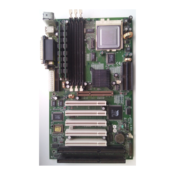
Chapter 3 Hardware Description Chapter 3 Hardware Description This chapter briefly describes each of the major features of the TI5VG+ motherboard. The layout of the board is shown in Figure 1 which shows the locations of the key components. The topics covered in this chapter are as follows: 3.1 Processor and CPU Voltage ............ - Page 10 Chapter 3 Hardware Description Figure 1: Layout of the TI5VG+ Motherboard TI5VG+ User’s Manual...
-
Page 11: Processor And Cpu Voltage
Chapter 3 Hardware Description 3.1 Processor and CPU Voltage The TI5VG+ is designed to take a Pentium Processor with a bus speed of 66, 75, 83 and 100 MHz. The internal clock of the CPU can be multiples of 1.5, 2, 2.5, 3, 3.5, 4, 4.5, 5 and 5.5 of the bus clock, the CPU frequency can be 100 to 550MHz. - Page 12 Chapter 3 Hardware Description (1) 72-pin SIMM (5V) - EDO DRAM (SIMM1, SIMM2) Total Memory 4MB×2 16MB 8MB×2 32MB 16MB×2 64MB 32MB×2 128MB 64MB×2 (2) 168-pin DIMM (3.3V) - SDRAM or EDO DRAM DIMM3 DIMM2 DIMM1 Total Memory ----- ----- 16MB ----- -----...
-
Page 13: Bios
Chapter 3 Hardware Description 168Pin DIMM (3.3V) - SDRAM or EDO DRAM (continued) DIMM3 DIMM2 DIMM1 Total Memory 64MB 16MB 16MB 96MB 128MB 16MB 16MB 160MB 32MB 32MB ----- 64MB 64MB 32MB ----- 96MB 128MB 32MB ----- 160MB 32MB 32MB 72MB 64MB 32MB... -
Page 14: Onboard Pci Eide
Chapter 3 Hardware Description 2. ISA Plug and Play (PnP) Extension Unlike PCI cards which are plug and play, ISA cards require setting jumpers to resolve hardware conflicts. To make a computer system PnP, an ISA PnP standard is established and supported by new OSes, such as Windows 95. -
Page 15: I/O Port Address Map
Chapter 3 Hardware Description 3.8 I/O Port Address Map Each peripheral device in the system is assigned a set of I/O port addresses which also becomes the identity of the device. There are a total of 1K port address space available. The following table lists the I/O port addresses used on the motherboard. -
Page 16: Interrupt Request Lines (Irq)
Chapter 3 Hardware Description 3.10 Interrupt Request Lines (IRQ) There are a total of 15 IRQ lines available on the motherboard. Peripheral devices use interrupt request lines to notify the CPU for the service required. The following table shows the IRQ used by the devices on the motherboard. -
Page 17: Chapter 4 Hardware Settings
Chapter 4 Hardware Settings Chapter 4 Hardware Settings The following sections describe the necessary procedures and proper jumper settings to configure the TI5VG+ motherboard. 4.1 SW1(1-8): CPU Frequency Selector ......... 15 4.2 JP1: DRAM Operating Frequency ..........20 4.3 SW2(1-4): CPU Voltage Selector ..........20 4.4 JP5: Clear CMOS Selection ............ - Page 18 Chapter 4 Hardware Settings Figure 2: Jumper Locations of the TI5VG+ TI5VG+ User’s Manual...
-
Page 19: Sw1(1-8): Cpu Frequency Selector
Chapter 4 Hardware Settings 4.1 SW1(1-8): CPU Frequency Selector For Intel Pentium, IDT WinChip 2-3D / C6 Multiplier CPU FREQ. Clock Clock 66MHz 66MHz 1.5x P54C-100 off on on off off off off on 66MHz 66MHz P54C-133 off on on off on off off on P54C/P55C-16 66MHz 66MHz 2.5x... - Page 20 Chapter 4 Hardware Settings For Cyrix 6x86, 6x86L, 6x86MX CPU Multiplier CPU FREQ. Clock Clock P166+ 66MHz 66MHz (133MHz) off on on off on off off on P200+ 75MHz 75MHz (150MHz) off off on off on off off on PR200 66MHz 66MHz 2.5x...
- Page 21 Chapter 4 Hardware Settings MII-380 100MHz 66MHz (300MHz) off off off on off on off off MII-400 95MHz 63MHz 3.5x (333MHz) on off off on off off off off MII-433 100MHz 66MHz 3.5x (350MHz) off off off on off off off off MII-450 95MHz 63MHz...
- Page 22 Chapter 4 Hardware Settings For AMD K5, K6, K6-2 CPU Multiplier CPU FREQ. Clock Clock 66MHz 66MHz 1.5x PR100 off on on off off off off on 66MHz 66MHz PR133 off on on off on off off on PR166 / 66MHz 66MHz 2.5x K6-166...
- Page 23 Chapter 4 Hardware Settings 95MHz 64MHz K6-2/380 on off off on on off on off 66MHz 66MHz K6-2/400 off on on off on off off on K6-2/400 100MHz 66MHz K6-3/400 off off off on on off on off K6-2/450* 100MHz 66MHz 4.5x K6-3/450* off off off on on on on off...
-
Page 24: Jp1: Dram Operating Frequency
Chapter 4 Hardware Settings 4.2 JP1: DRAM Operating Frequency SDRAM Frequency pin 1-2 short Run CPU Clock pin 2-3 short Run AGP Clock Set the SDRAM Frequency to Run CPU Clock only when the CPU clock is 100MHz and the DIMM modules are PC-100. 4.3 SW2(1-4): CPU Voltage Selector For Single Voltage CPU: CORE... - Page 25 Chapter 4 Hardware Settings For Dual Voltage CPU: Intel P55C, Cyrix 6x86L/MX/MII, AMD K6/K6-2, IDT WinChip 2-3D CORE K6-233 3.3V 3.2V (0.35µ) off off on on 3.3V 3.1V on on off on 3.3V 3.0V off on off on K6-166/200 3.3V 2.9V 6x86MX on off off on...
-
Page 26: Jp5: Clear Cmos Selection
Chapter 4 Hardware Settings For Dual Voltage CPU: Intel P55C, Cyrix 6x86L/MX/MII, AMD K6/K6-2 CORE K6, K6-2 3.3V 2.2V (0.25µ) off on off off 3.3V 2.1V on off off off 3.3V 2.0V off off off off 4.4 JP5: Clear CMOS Selection Use JP5, a 3-pin header, to clear the contents of the CMOS RAM. -
Page 27: Chapter 5 Installation
Chapter 5 Installation Chapter 5 Installation This chapter describes the connectors and interfaces that the TI5VG+ provides for creating a working system. Refer to Figure 3 for the location of the connectors. The following items are covered in this chapter: 5.1 I/O Connectors ................ - Page 28 Chapter 5 Installation Figure 3: Connector Location on the TI5VG+ TI5VG+ User’s Manual...
-
Page 29: I/O Connectors
Chapter 5 Installation 5.1 I/O Connectors The I/O connectors connect the TI5VG+ to the most common peripherals. To attach cables to these connectors, carefully align Pin 1 of the cables to that of the connectors. Refer to Figure 4 for the location and orientation of the connectors. -
Page 30: J2: Usb Connector
Chapter 5 Installation 5.3 J2: USB Connector J2 is the standard USB external connector consisting of two ports. USB support allows connections of up to 64 plug and play external peripherals per channel. The following table shows the pin outs of these ports. J2 Pin # Signal Name USB0... -
Page 31: J4: Parallel Port Connector
Chapter 5 Installation 5.5 J4: Parallel Port Connector J4 is a DB-25 external connector. The following table describes the pin- out assignments of this connector. See the figure on the previous page. Signal Name Pin # Pin # Signal Name Line printer strobe AutoFeed PD0, parallel data 0... -
Page 32: J7: Floppy Drive Connector
Chapter 5 Installation 5.7 J7: Floppy Drive Connector J7 of the TI5VG+ is a 34-pin header and will support up to 2.88MB floppy drives. Signal Name Pin # Pin # Signal Name Ground RM/LC Ground No connect Ground No connect Ground Index Ground... -
Page 33: Ide1, Ide2: Eide Connectors
Chapter 5 Installation 5.8 IDE1, IDE2: EIDE Connectors IDE1: Primary IDE Connector Signal Name Pin # Pin # Signal Name Reset IDE Ground Host data 7 Host data 8 Host data 6 Host data 9 Host data 5 Host data 10 Host data 4 Host data 11 Host data 3... -
Page 34: J8: Cpu Fan Power Connector
Chapter 5 Installation 5.9 J8: CPU Fan Power Connector J8 is a 3-pin header for the CPU fan power connector. The fan must be a 12V fan. Pin # Signal Name Fan sensor +12V 3 2 1 Ground 5.10 J9: IrDA Connector This connector is used for an IrDA connector that supports infrared wireless communication with IrDA devices. -
Page 35: J13 Front Bezel Connector
Chapter 5 Installation 5.13 J13 Front Bezel Connector The front bezel of the case has a control panel which provides light indication of the computer activities and switches to change the computer status. J13 is a 20-pin header that provides interfaces for the following functions. - Page 36 Chapter 5 Installation CPU Overheat LED: Pins 6 and 16 This connector connects to the CPU Overheat LED that lights up when CPU temperature exceeds the CPU warning temperature set in the BIOS. When this occurs, the system slows down until the temperature falls to a safe level.
-
Page 37: Chapter 6 Bios Configuration
Chapter 6 BIOS Configuration Chapter 6 BIOS Configuration This chapter describes the different settings available in the Award BIOS that comes with the TI5VG+ motherboard. The topics covered in this chapter are as follows: 6.1 BIOS Introduction ............36 6.2 BIOS Setup ..............36 6.3 Standard CMOS Setup ............38 Date Time... - Page 38 Chapter 6 BIOS Configuration DRAM Read Pipeline Sustained 3T Write Cache Rd+CPU Wt Pipeline Read Around Write Cache Timing Video BIOS Cacheable System BIOS Cacheable Memory Hole at 15MB Addr. AGP Aperture Size Cyrix M2 ADS# delay CPU/PCI Clock Select Auto Detect DIMM/PCI Clk Spread Spectrum OnChip USB...
- Page 39 Chapter 6 BIOS Configuration PCI IRQ Activated by Assign IRQ for USB/VGA 6.8 Load BIOS Defaults ............52 6.9 Load Setup Defaults ............52 6.10 Integrated Peripherals ............53 OnChip Primary/Secondary PCI IDE IDE Prefetch Mode IDE HDD Block Mode IDE Primary/Secondary Master/Slave PIO IDE Primary/Secondary Master/Slave UDMA Onboard FDD Controller Onboard Serial/Parallel Port...
-
Page 40: Bios Introduction
Chapter 6 BIOS Configuration 6.1 BIOS Introduction The Award BIOS (Basic Input/Output System) installed in your computer system’s ROM supports Intel/Cyrix/AMD processors in a standard IBM-AT compatible I/O system. The BIOS provides critical low-level support for standard devices such as disk drives, serial and parallel ports. - Page 41 Chapter 6 BIOS Configuration ROM PCI/ISA BIOS CMOS SETUP UTILITY AWARD SOFTWARE, INC. STANDARD CMOS SETUP INTEGRATED PERIPHERALS BIOS FEATURES SETUP SUPERVISOR PASSWORD CHIPSET FEATURES SETUP USER PASSWORD POWER MANAGEMENT SETUP IDE HDD AUTO DETECTION PNP/PCI CONFIGURATION HDD LOW LEVEL FORMAT LOAD BIOS DEFAULTS SAVE &...
-
Page 42: Standard Cmos Setup
Chapter 6 BIOS Configuration 6.3 Standard CMOS Setup “Standard CMOS Setup” choice allows you to record some basic hardware configurations in your computer system and set the system clock and error handling. If the motherboard is already installed in a working system, you will not need to select this option. - Page 43 Chapter 6 BIOS Configuration Time The time format is: Hour : 00 to 23 Minute : 00 to 59 Second : 00 to 59 To set the time, highlight the “Time” field and use the <PgUp>/ <PgDn> or +/- keys to set the current time. Primary HDDs / Secondary HDDs The onboard PCI IDE connectors provide Primary and Secondary channels for connecting up to four IDE hard disks or other IDE devices.
- Page 44 Chapter 6 BIOS Configuration The specifications of your drive must match with the drive table. The hard disk will not work properly if you enter incorrect information in these fields. If your hard disk drive type is not matched or listed, you can use Type User to define your own drive type manually.
-
Page 45: Bios Features Setup
Chapter 6 BIOS Configuration 6.4 BIOS Features Setup This section allows you to configure and improve your system and allows you to set up some system features according to your preference. ROM / PCI ISA BIOS BIOS FEATURES SETUP AWARD SOFTWARE, INC. Virus Warning Video BIOS Shadow : Enabled... - Page 46 Chapter 6 BIOS Configuration Quick Power On Self Test This choice speeds up the Power On Self Test (POST) after you power up the system. If it is set to Enabled, BIOS will skip some items. By default, this choice is Enabled. Boot Sequence This field determines the drive that the system searches first for an operating system.
- Page 47 Chapter 6 BIOS Configuration Typematic Rate Setting When disabled, continually holding down a key on your keyboard will generate only one instance. When enabled, you can set the two typematic controls listed next. By default, this field is set to Disabled. Typematic Rate (Chars/Sec) When the typematic rate is enabled, the system registers repeated keystrokes speeds.
-
Page 48: Chipset Features Setup
Chapter 6 BIOS Configuration 6.5 Chipset Features Setup This Setup menu controls the configuration of the motherboard chipset. ROM PCI/ISA BIOS CHIPSET FEATURES SETUP AWARD SOFTWARE INC. Bank 0/1 DRAM Timing : 60ns OnChip USB : Enabled Bank 2/3 DRAM Timing : 60ns USB Keyboard Support : Disabled... - Page 49 Chapter 6 BIOS Configuration Read Around Write DRAM optimization feature: If a memory read is addressed to a location whose latest write is being held in a buffer before being written to memory, the read is satisfied through the buffer contents, and the read is not sent to the DRAM.
- Page 50 Chapter 6 BIOS Configuration CPU/PCI Clock Select The default settings for the CPU/PCI clock are 66/33MHz (default) and 100/33MHz, depending on the bus speed of the CPU you have installed. If overclocking causes the system to be unstable, use the defaults. Note that 112/37MHz, 124/41MHz and 133/44MHz settings are only supported if your motherboard has an ICS 9148AF-58 clock generator.
-
Page 51: Power Management Setup
Chapter 6 BIOS Configuration 6.6 Power Management Setup ROM PCI/ISA BIOS (2A59IM29) POWER MANAGEMENT SETUP AWARD SOFTWARE, INC. Power Management : User Define Primary INTR : ON PM Control by APM : Yes IRQ3 (COM2) : Primary Video Off Option : Suspend ->... - Page 52 Chapter 6 BIOS Configuration Video Off Method This field defines the Video Off features. There are three options. V/H SYNC + Blank Default setting, blank the screen and turn off vertical and horizontal scanning. DPMS Allows the BIOS to control the video display card if it supports the DPMS feature.
-
Page 53: Pnp/Pci Configuration
Chapter 6 BIOS Configuration PM Events The VGA, LPT & COM, HDD & FDD, DMA /master, Modem Ring Resume, RTC Alarm Resume and Primary INTR section are I/O events which can prevent the system from entering a power saving mode or can awaken the system from such a mode. - Page 54 Chapter 6 BIOS Configuration PNP OS Installed This field allows you to specify if the operating system installed in your system is plug and play aware. Note: Operating systems such as DOS, OS/2, and Windows 3.x do not use PnP. Resources Controlled by This PnP BIOS can configure all of the boot and compatible devices automatically.
-
Page 55: Pci Irq Activated By
Chapter 6 BIOS Configuration PCI Master Read Prefetch When this item is enabled, the system is allowed to prefetch the next read and initiate the next process. By default, this field is set to Enabled. PCI#2 Access #1 Retry This item enables PC#2 Access #1 attempts. By default, this field is set to Disabled. -
Page 56: Load Bios Defaults
Chapter 6 BIOS Configuration 6.8 Load BIOS Defaults This option allows you to load the troubleshooting default values permanently stored in the BIOS ROM. These default settings are non-optimal and disable all high-performance features. ROM PCI/ISA BIOS CMOS SETUP UTILITY AWARD SOFTWARE, INC. -
Page 57: Integrated Peripherals
Chapter 6 BIOS Configuration 6.10 Integrated Peripherals This option sets your hard disk configuration, mode and port. ROM PCI/ISA BIOS INTEGRATED PERIPHERALS AWARD SOFTWARE INC. OnChip IDE First Channel : Enabled Onboard Parallel Mode : SPP OnChip IDE Second : Enabled Channel IDE Prefetch Mode : Disabled... -
Page 58: Ide Primary/Secondary Master/Slave Udma
Chapter 6 BIOS Configuration The system supports five modes, numbered from 0 (default) to 4, which primarily differ in timing. When Auto is selected, the BIOS will select the best available mode. IDE Primary/Secondary Master/Slave UDMA This field allows your system to improve disk I/O throughput to 33Mb/sec with the Ultra DMA/33 feature. -
Page 59: Supervisor / User Password
Chapter 6 BIOS Configuration 6.11 Supervisor / User Password These two options set the system password. Supervisor Password sets a password that will be used to protect the system and Setup utility. User Password sets a password that will be used exclusively on the system. To specify a password, highlight the type you want and press <Enter>. -
Page 60: Ide Hdd Auto Detection
Chapter 6 BIOS Configuration 6.12 IDE HDD Auto Detection This option detects the parameters of an IDE hard disk drive, and automatically enters them into the Standard CMOS Setup screen. ROM PCI/ISA BIOS STANDARD CMOS SETUP AWARD SOFTWARE, INC. HARD DISKS TYPE SIZE CYLS... -
Page 61: Save & Exit Setup
Chapter 6 BIOS Configuration 6.14 Save & Exit Setup This option allows you to determine whether to accept the modifications or not. If you type “Y”, you will quit the setup utility and save all changes into the CMOS memory. If you type “N”, you will return to Setup utility. ROM PCI/ISA BIOS CMOS SETUP UTILITY AWARD SOFTWARE, INC. - Page 62 Chapter 7 LANDesk User’s Guide Chapter 7 LANDesk User’s Guide This chapter gives a brief introduction to the optional LANDesk Client Manager (LDCM) utility, as well as the installation procedures. The following items are covered in this chapter: 7.1 Introduction ..............60 7.2 Installation ...............61 7.2.1 Installing the Local Version of LDCM 7.2.2 Installing the Administrator Version of LDCM...
-
Page 63: Chapter 7 Landesk User's Guide
Chapter 7 LANDesk User’s Guide 7.1 Introduction LANDesk Client Manager (LDCM 3.1 ) provides the capability for managing components (network interface cards, memory, printers, software applications, etc.) within a PC system. It uses the Desktop Management Interface (DMI) standard established by the Desktop Management Task Force (DMTF). -
Page 64: Installation
Chapter 7 LANDesk User’s Guide 7.2 Installation The optional LANDesk utility that comes with the CPU card runs in Windows NT or Windows 95 operating system. Upon entering the Windows NT 4.0 or Windows 95 environment, insert the CD. Windows will autorun the installation program and show the following screen. - Page 65 Chapter 7 LANDesk User’s Guide 7.2.1 Installing the Local Version of LDCM Double Click on ‘LANDesk Client Manager’ in the initial screen and the following screen will appear. Double click on the local version of LANDesk Client Manager. When the Welcome screen appears, click on “Next” to continue with Setup.
- Page 66 Chapter 7 LANDesk User’s Guide Choose the directory location where Setup will install LANDesk Client Manager. Click “Browse” if you want to change the directory suggested. Otherwise, click “Next” to start installing LDCM. When Setup is finished, changes will have been made to the file AUTOEXEC.BAT.
- Page 67 Chapter 7 LANDesk User’s Guide 7.2.2 Installing the Administrator Version of LDCM After double clicking on ‘LANDesk Client Manager’ in the initial screen, select the administrator version of the LDCM and the Welcome screen below will appear. Click on “Next” to continue. The screen below allows you to install the documentation in Adobe Acrobat format and the Adobe Acrobat Reader software.
- Page 68 Chapter 7 LANDesk User’s Guide After LANDesk Client Manager Setup is complete, restart your computer to be able to use the LANDesk Client Manager. TI5VG+ User’s Manual...
Need help?
Do you have a question about the TI5VG+ and is the answer not in the manual?
Questions and answers