Elation DESIGN SPOT 575E User Manual
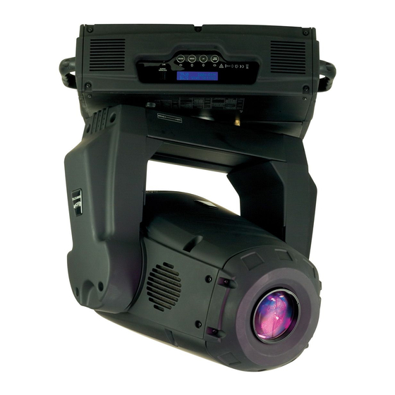
Professional moving head
Hide thumbs
Also See for DESIGN SPOT 575E:
- User manual (54 pages) ,
- Instruction manual (31 pages) ,
- User instructions (48 pages)

Related Manuals for Elation DESIGN SPOT 575E


Summary of Contents for Elation DESIGN SPOT 575E
- Page 1 PROFESSIONAL MOVING HEAD USER’S MANUAL DESIGN SPOT 575E KEEP THIS MANUAL FOR FUTURE NEEDS...
- Page 2 For your own safety, please read this user manual carefully before installing the device. K eep thi s dev i ce aw ay f rom rai n and moi sture ! U npl ug mai ns l ead bef ore openi ng the housi ng. Every person involved with the installation, operation and maintenance of this device has to: -be qualified -follow carefully the instructions of this manual...
-
Page 3: Safety Instructions
·Motorized linear zoom from 16° ~ 30° ·Linear dimmer in precise speed from 0~100% ·Stepless iris , 5%~100% linear change iris, pulse iris effect ·Stepless frost, 0%~100% linear change frost ·Preset variable iris, dimmer, shutter, frost pulse effects ·Strobe effect with 1-10 flashes per second or random strobe via shutter ·Friendly colored LCD display ·Battery buffered Control Board for operation time readouts etc ·Local and remote lamp on/off... -
Page 4: General Guidelines
During initial start-up some smoke or smell may arise. This is a normal process and does not necessarily mean that the device is defective, it should decrease gradually. CA UTION Never touch the device during operation! The housing may heat up CA UTION Never look directly into the light source, as sensitive persons may suffer an epileptic shock. -
Page 5: Installation Instructions
persons not qualified for operating the device. Most damages are the result of unprofessional operation. Please use the original packaging if the device is to be transported. For safety reasons, please be aware that all modifications on the device are forbidden. If this device will be operated in any way different to the one described in this manual, the product may suffer damages and the guarantee becomes void. -
Page 6: Mounting The Device
CA UTION Do not operate this device with open cover b) Mounting the device CA UTION Please consider the EN 60598-2-17 and the other respective national norms during the installation. The installation must only be carried out by a qualified person. The installation of the effect has to be built and constructed in a way that it can hold 10 times the weight for 1 hour without any harming deformation. -
Page 7: Dmx-512 Control Connection
installation can result in bodily injury. CA UTION The electric connection must only be carried out by a qualified electrician. Before mounting make sure that the installation area can hold a minimum point load of 10 times the device’s weight. Connect the fixture to the mains with the power plug installation via the Omega holders Screw one clamp each via a M12 screw and nut onto the Omega holders. -
Page 8: Dmx-512 Connection With Dmx Terminator
to the male 3-pin XLR input of the moving head. You can chain multiple Moving head together through serial linking. The cable needed should be two core, screened cable with XLR input and output connectors. Please refer to the diagram below. output Input output... -
Page 9: Control Board
You can set the same starting address for all fixtures or a group of fixtures, or make different address for each fixture individually. If you set the same address, all the units will start to “listen” to the same control signal from the same channel number. - Page 10 Status Settings Add. via DMX Address via DMX ON/OFF Auto run if no DMX No DMX Status Auto/Music/Close/Hold Pan Reverse movement Pan Reverse ON/OFF Tilt Reverse movement Tilt Reverse ON/OFF Fine resolution switch Fine Resolution ON/OFF Pan Degree Select Pan Degree 630/540 Scan Feedback switch Feedback...
-
Page 11: Function Mode
Function Mode DMX address setting With this function, you can adjust the desired DMX-address via the Control Board. • Select “Set DMX address“ via the encoder. • Press the encoder, adjust the DMX address by turning the encoder. • Press the encoder to confirm. •... -
Page 12: Software Version
Software version With this function , you can display the software version of the device. • Select “Software version” by turning the encoder. • Press the encoder, the display shows “V-X.X”, “X.X“ stands for the version number, e.g. “V-1.0”, “V-2.6”. •... -
Page 13: Reset Functions
1 to "7", channel 2 to "7" and channel 3 to "57". If you want to set the starting address to 420,set channel 1 to "7", channel 2 to "8" and channel 3 to "164" (256+164=420). • Wait for approx. 20 seconds and the unit will carry out a reset. After that, the new starting address is set. Run If No DMX With this function, when the drive is not DMX signal, it runs automatism. -
Page 14: Users Mode Set
Calibrate values With this function, you can calibrate and adjust the effect wheels to their correct positions. The password of calibrate values is 050. Users mode set User mode With this function, you can create user defined channel orders. Edit User mode With this function, you can adjust the preset user defined channel order. - Page 15 DMX channel (24 DMX channels): DESIGN SPOT 575E Channel 1 - PAN movement 8bit : Channel 2 – Pan fine 16bit Channel 3 - TILT movement 8bit : Channel 4– Tilt fine 16bit Channel 5 - Color Wheel : 0-13...
- Page 16 40-49 Rot. gobo 4 50-59 Rot. gobo 5 60-69 Rot. gobo 6 70-89 Gobo 1 shake slow to fast 90-109 Gobo 2 shake slow to fast 110-129 Gobo 3 shake slow to fast 130-149 Gobo 4 shake slow to fast 150-169 Gobo 5 shake slow to fast 170-189...
- Page 17 Channel 13- 3 facet rotating prism, Prism / Gobo macros: open 4-63 Forwards rotation from fast to slow 64-67 No rotation 68-127 Backwards rotation from slow to fast 128-135 Macro 1 136-143 Macro 2 144-151 Macro 3 152-159 Macro 4 160-167 Macro 5 168-175...
- Page 18 0-255 Intensity 0 to 100% Channel 18– Iris: 0-191 Max. diameter to Min.diameter 192-223 Pulse closing fast to slow 224-255 Pulse opening slow to fast Channel 19 –Frost: 0-191 Frost 0~100% 192-223 Pulse opening fast to slow 224-254 Pulse closing slow to fast Max.
- Page 19 0-225 max to min speed 226-235 blackout by movement 236-245 blackout by all wheel changing 246-255 no function Channel 24– Lamp on/off, reset, internal programs: 0-19 colour change normal 20-39 colour change to any position 40-59 Lamp on 60-79 Lamp switch off 80-84 All motor reset 85-87...
-
Page 20: Error Message
ERROR MESSAGE When you turn on the fixture, it will make a reset first. The display may show “XXer” while there are problems with one or more channels. “XX” stands for channel PAN- movement, TILT- movement, Cyan Color, Magenta Color, Yellow Color, Color, Rotation gobo, Gobo Rotation, Prism Rotation, Shutter, Strobe, Focus, Stepless Zoom, Iris, Fire wheel who has the testing sensor for positioning. -
Page 21: Cleaning And Maintenance
(Rotating gobo wheel 2- error) This message will appear after the reset of the fixture if the yoke’s magnetic-indexing circuit malfunction (sensor failed or magnet missing) or the stepping-motor is defective ( or its driving IC on the main PCB). The Rotating gobo wheel 2 is not located in the default position after the reset. Gobo Rotation Er (Gobo Rotation wheel 2- error) This message will appear after the reset of the fixture if the yoke’s magnetic-indexing circuit malfunction (sensor failed or magnet missing) or the stepping-motor is defective ( or its driving IC on the main... -
Page 22: Technical Specifications
2) The electric power supply cables must not show any damage, material fatigue or sediments. Further instructions depending on the installation spot and usage have to be adhered by a skilled installer and any safety problems have to be removed. CA UTION Disconnect from mains before starting maintenance operation.
Need help?
Do you have a question about the DESIGN SPOT 575E and is the answer not in the manual?
Questions and answers