Table of Contents
Advertisement
Advertisement
Table of Contents

Related Manuals for Elation PALADIN Panel


Summary of Contents for Elation PALADIN Panel
- Page 1 PALADIN PANEL™ User Manual...
- Page 2 +31 45 546 85 66 | +31 45 546 85 96 fax | www.elationlighting.eu | info@elationlighting.eu Elation Professional Mexico | AV Santa Ana 30 | Parque Industrial Lerma, Lerma, Mexico 52000 +52 (728) 282-7070 D O C U M E N T V E R S I O N...
-
Page 3: Table Of Contents
C O N T E N T S General Information Warranty Returns (USA Only) Safety Guidelines Maintenance Guidelines Fixture Overview Fixture Installation System Menu Pixel Zone Control E-FLY Wireless DMX Set Up DMX Channel Functions and Values Specifications Optional Accessories... -
Page 4: General Information
Please do not return this device to your dealer without first contacting customer support. Please do not discard the shipping carton in the trash. Please recycle whenever possible. CUSTOMER SUPPORT Contact ELATION Service for any product related service and support needs. Also visit forums.elationlighting.com with questions, comments or suggestions. -
Page 5: Warranty Returns (Usa Only)
ELATION in Los Angeles, CA or to an ELATION Authorized Service Center. The RMA number must be clearly written on the outside of the return box and a brief description of the problem and the RMA number must be documented and included in the box. -
Page 6: Safety Guidelines
This fixture is a sophisticated piece of electronic equipment. To guarantee a smooth operation, it is important to follow all instructions and guidelines in this manual. Elation Professional is not responsible for injury and/or damages resulting from the misuse of this fixture due to the disregard of the information printed in this manual. - Page 7 S A F E T Y G U I D E L I N E S DO NOT TOUCH the fixture housing during operation. Turn OFF the power and allow approximately 15 minutes for the fixture to cool down before serving. DO NOT shake fixture, avoid brute force when installing and/or operating fixture.
-
Page 8: Maintenance Guidelines
Regular inspections are recommended to insure proper function and extended life. There are no user serviceable parts inside this fixture, please refer all other service issues to an authorized Elation service technician. Should you need any spare parts, please order genuine parts from your local Elation dealer. -
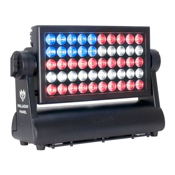
Page 9: Fixture Overview
F I X T U R E O V E R V I E W FRONT LED Array Removable Magnetic Frost Filter SIDES Manual Tilt Adjustment Knobs BACK Carrying Handle OLED Control System Menu Display Mode, Down, Up, Enter Buttons IP65 Twist Lock Power In/Out IP65 5pin DMX In/Out E-FLY Wireless DMX Antenna... -
Page 10: Fixture Installation
F I X T U R E I N S T A L L A T I O N FLAMMABLE MATERIAL WARNING Keep fixture minimum 5.0 feet (1.5m) away from flammable materials and/or pyrotechnics. ELECTRICAL CONNECTIONS A qualified electrician should be used for all electrical connections and/or installations. USE CAUTION WHEN POWER LINKING OTHER MODEL FIXTURES AS THE POWER CONSUMPTION OF OTHER MODEL FIXTURES MAY EXCEED THE MAX POWER OUTPUT ON THIS FIXTURE. - Page 11 F I X T U R E I N S T A L L A T I O N OMEGA BRACKETS INSTALLATION Insert 1 or both Omega Brackets into the matching holes on the bottom of the fixture. Secure the Omega Brackets to the fixture by turning each quick-lock fastener ¼ turn clockwise; making sure the fastener is completely locked.
- Page 12 F I X T U R E I N S T A L L A T I O N RIGGING Overhead rigging requires extensive experience, including amongst others calculating working load limits, installation material being used, and periodic safety inspection of all installation material and the fixture.
- Page 13 F I X T U R E I N S T A L L A T I O N POWER AND DATA CONNECTIONS ENSURE ALL CONNECTIONS AND END CAPS ARE PROPERLY SEALED WITH A DIELECTRIC GREASE (AVAILABLE AT MOST ELECTRICAL SUPPLIERS) PREVENT WATER CORROSION AND/OR ELECTRICAL SHORT CIRCUIT.
- Page 14 LEDs. This issue is not specific only to ELATION lighting fixtures, it is a common issue with lighting fixtures from all manufacturers. Although there is no true way to fully prevent this issue from happening, the guidelines below can prevent any potential damage from occurring if followed.
-
Page 15: System Menu
S Y S T E M M E N U The fixture includes an easy to navigate system menu. The control panel (see image below) located on the front of the fixture, provides access to the main system menu and is where all necessary system adjustments are made to the fixture. - Page 16 ELATION PALADIN PANEL™ - SYSTEM MENU Supports Software Versions: ≥ 1.01 Features are subject to change without notice. MENU SUB MENU OPTIONS / VALUES DESCRIPTION (Default Settings in BOLD) Address Set ADDR 001 - 497 Set DMX Address Extended 16CH...
- Page 17 ELATION PALADIN PANEL™ - SYSTEM MENU Supports Software Versions: ≥ 1.01 MENU SUB MENU OPTIONS / VALUES DESCRIPTION (Default Settings in BOLD) 900 HZ, 1000HZ, 1100HZ, 1200HZ, 1300HZ, 1400HZ, 1500HZ, Frequen Set LED Refresh Frequency Rate 2500HZ, 4000HZ, 5000HZ, 10kHZ, 15kHZ, 20kHZ, 25kHZ...
- Page 18 ELATION PALADIN PANEL™ - SYSTEM MENU Supports Software Versions: ≥ 1.01 MENU SUB MENU OPTIONS / VALUES DESCRIPTION (Default Settings in BOLD) Password Password=XXX (050) Channel Data Calibration Password Red1 050 ~ 255 Green1 050 ~ 255 Blue1 050 ~ 255...
-
Page 19: Pixel Zone Control
P I X E L Z O N E C O N T R O L This fixture includes 10-pixel zones, each zone containing 5 LED pixels which can be controlled when specific DMX channel modes are selected. The system menu includes a FLIP setting which flips the pixel zones to support unique fixture mounting scenarios. -
Page 20: E-Fly Wireless Dmx Set Up
E - F L Y W I R E L E S S D M X S E T U P BEFORE SETTING THE WIRELESS CHANNEL ON ANY E-FLY FIXTURE, MAKE SURE THE CONTROLLING E-FLY WIRELESS DMX TRANSCEIVER DEVICE IS OFF. TO CONTROL FIXTURE WITH E-FLY WIRELESS DMX SIGNAL 1. - Page 21 WIRELESS E-FLY INSTALLATION LOCATION GUIDELINES Wireless DMX signal can penetrate walls, glass, metal, and most objects. However, there are many factors that can affect and/or interrupt the wireless DMX signal, one of which is people. Therefore, it is highly recommended to position the wireless antenna a minimum of 9.8 ft.
-
Page 22: Dmx Channel Functions And Values
D M X C H A N N E L F U N C T I O N S A N D V A L U E S ELATION PALADIN PANEL™ RGB MODES - DMX Channel Values / Functions (88 Total DMX Channels) Supports Software Versions: ≥... - Page 23 16bit Cells 16bit Extended Cells Ext-Cells Value Function Default Snap 16CH 80CH 88CH 10CH 82CH Dim Modes 0-20 Standard 21-40 Stage 41-60 61-80 Architectural 81-100 Theatre 101-120 Stage 2 Dimmer Delay Time 0.1s (default) 0.2s 0.3s 0.4s 0.5s 0.6s 0.7s 0.8s 0.9s 1.0s...
- Page 24 16bit Cells 16bit Extended Cells Ext-Cells Value Function Default Snap 16CH 80CH 88CH 10CH 82CH Control 0-19 Idle 20-24 Program 1 25-29 Program 2 30-34 Program 3 35-39 Program 4 40-44 Program 5 45-49 Program 6 50-54 Program 7 55-59 Program 8 60-64 Program 9...
- Page 25 16bit Cells 16bit Extended Cells Ext-Cells Value Function Default Snap 16CH 80CH 88CH 10CH 82CH Program Speed 0 - 255 Speed (slow → fast) Program Fade 0 - 255 Fade (slow → fast) Color Macros 0 - 255 Macro (1→ 64) 0 - 255 0 →...
- Page 26 16bit Cells 16bit Extended Cells Ext-Cells Value Function Default Snap 16CH 80CH 88CH 10CH 82CH Red1 0 - 255 0 → 100% Red1 Fine 0 - 255 0 → 100% Green1 0 - 255 0 → 100% Green1 Fine 0 - 255 0 →...
- Page 27 16bit Cells 16bit Extended Cells Ext-Cells Value Function Default Snap 16CH 80CH 88CH 10CH 82CH Red4 0 - 255 0 → 100% Red4 Fine 0 - 255 0 → 100% Green4 0 - 255 0 → 100% Green4 Fine 0 - 255 0 →...
- Page 28 16bit Cells 16bit Extended Cells Ext-Cells Value Function Default Snap 16CH 80CH 88CH 10CH 82CH Red7 0 - 255 0 → 100% Red7 Fine 0 - 255 0 → 100% Green7 0 - 255 0 → 100% Green7 Fine 0 - 255 0 →...
- Page 29 16bit Cells 16bit Extended Cells Ext-Cells Value Function Default Snap 16CH 80CH 88CH 10CH 82CH Red10 0 - 255 0 → 100% Red10 Fine 0 - 255 0 → 100% Green10 0 - 255 0 → 100% Green10 Fine 0 - 255 0 →...
- Page 30 ELATION PALADIN PANEL™ HSI MODES - DMX Channel Values / Functions (38 Total DMX Channels) Supports Software Versions: ≥ 1.0.1 Features subject to change without notice. *Pixel Zone Control depends on DMX Mode, Flip setting, and fixture head tilt position.
- Page 31 HSI-Ext HSI-Cell HSI 4CH Value Function Default Snap 10CH 38CH Dim Modes 0 - 20 Standard 21 - 40 Stage 41 - 60 61- 80 Architectural 81- 100 Theatre 101- 120 Stage 2 Dimmer Delay Time 0.1s(default) 0.2s 0.3s 0.4s 0.5s 0.6s 0.7s...
- Page 32 HSI-Ext HSI-Cell HSI 4CH Value Function Default Snap 10CH 38CH Control 0 -19 Idle 20-24 Program 1 25-29 Program 2 30-34 Program 3 35-39 Program 4 40-44 Program 5 45-49 Program 6 50-54 Program 7 55-59 Program 8 60-64 Program 9 65-69 Program 10 70-74...
- Page 33 HSI-Ext HSI-Cell HSI 4CH Value Function Default Snap 10CH 38CH Program Speed 0 - 255 Speed (slow → fast) Program Fade 0 - 255 Fade (slow → fast) Color Macros 0 - 255 Macro (1→ 64) 0 - 255 0 → 100% Saturation 0 - 255 0 →...
- Page 34 HSI-Ext HSI-Cell HSI 4CH Value Function Default Snap 10CH 38CH Hue 5 0 - 255 0 → 100% Saturation 5 0 - 255 0 → 100% Intensity 5 0 - 255 0 → 100% Hue 6 0 - 255 0 → 100% Saturation 6 0 - 255 0 →...
-
Page 35: Specifications
S P E C I F I C A T I O N S SOURCE (50) 15W RGBW LEDs 50,000 Hour Average LED Life* *Test lab conditions. May vary depending on several factors including but not limited to: Environmental Conditions, Power/Voltage, Usage Patterns (On-Off Cycling), Control, and Dimming. COLOR RGBW CONTROL / CONNECTIONS... - Page 36 DIMENSIONAL DRAWINGS Specifications and improvements in the design of this unit and this manual are subject to change without notice.
-
Page 37: Optional Accessories
O P T I O N A L A C C E S S O R I E S ORDER CODE ITEM IP TESTER IP Fixture Vacuum and Pressure Leak Tester TRIGGER CLAMP Heavy Duty Wrap Around Hook Style Clamp SIP126 5 ft.
Need help?
Do you have a question about the PALADIN Panel and is the answer not in the manual?
Questions and answers