
Related Manuals for Advantech EKI-2748FI


Summary of Contents for Advantech EKI-2748FI
-
Page 1: User Manual
EKI-2748FI 8G ports Industrial Managed Redundant Gigabit Ethernet Switch, 4 Gigabit Copper and 4 Gigabit SFP User Manual... - Page 2 The documentation and the software included with this product are copyrighted 2010 by Advantech Co., Ltd. All rights are reserved. Advantech Co., Ltd. reserves the right to make improvements in the products described in this manual at any time without notice. No part of this manual may be reproduced, copied, translated or transmitted in any form or by any means without the prior written permission of Advantech Co., Ltd.
- Page 3 Because of Advantech′s high quality-control standards and rigorous testing, most of our customers never need to use our repair service. If an Advantech product is defective, it will be repaired or replaced at no charge during the warranty period. For out-of-warranty repairs, you will be billed according to the cost of replacement materials, service time and freight.
- Page 4 Step 2. Contact your distributor, sales representative, or Advantech’s customer service center for technical support if you need additional assistance. Please have the following information ready before you call: - Product name and serial number...
- Page 5 Safety Instructions 1. Read these safety instructions carefully. 2. Keep this User's Manual for later reference. 3. Disconnect this equipment from any AC outlet before cleaning. Use a damp cloth. Do not use liquid or spray detergents for cleaning. 4. For plug-in equipment, the power outlet socket must be located near the equipment and must be easily accessible.
- Page 6 Safety Precaution - Static Electricity Follow these simple precautions to protect yourself from harm and the products from damage. 1. To avoid electrical shock, always disconnect the power from your equipment chassis before you work on it. 2. Disconnect power before making any configuration changes. EKI-2748FI_Manual...
-
Page 7: Table Of Contents
1.4 Packing List............17 1.5 Safety Precaution..........17 Chapter 2 Installation........20 2.1 LED Indicators............. 20 Table 2.1: EKI-2748FI LED Definition........20 2.2 Dimensions (unit: mm) ........21 Figure 2.1: Front View..............21 Figure 2.2: Side View ..............22 Figure 2.3: Rear View..............23 Figure 2.4: Top View..............24... - Page 8 Figure 3.1-3 COM Port Properties Setting ......37 Figure 3.1-4 Login Screen: RS-232 Configuration ....37 Figure 3.1-5 Command Line Interface ........38 3.2 Commands Set ........... 39 3.2.1 Commands Level........39 Table 3.1: Command Level............39 3.2.2 Commands Set List ......... 39 Table 3.2: Commands Set List............39 3.2.3 System Commands Set......
- Page 9 3.3.1 System............. 53 Figure 3.3-4 System Information..........53 Figure 3.3-5 IP Configuration..........54 Figure 3.3-6 DHCP Server - System Configuration....55 Figure 3.3-7 DHCP Server – Client Entries ......56 Figure 3.3-8 DHCP Server – Port & IP Binding .....57 Figure 3.3-9 TFTP – Update Firmware ........58 Figure 3.3-10 TFTP –...
- Page 10 Figure 3.3-47 802.1x/Radius - Misc Configuration....99 Figure 3.3-48 Static MAC Addresses interface.......100 Figure 3.3-49 MAC Filtering interface........101 Figure 3.3-50 All MAC Address interface ......102 Figure 3.3-51 Multicast Filtering interface......103 Figure 3.3-52 Factory Default interface ........104 Figure 3.3-53 Save Configuration interface ......105 Figure 3.3-54 System Reboot interface ........106 Chapter 4 Troubleshooting ......109...
- Page 11 Overview Sections include: Introduction Features Specifications Packing List Safety Precaution Contents...
-
Page 12: Introduction
1.1.1 The SFP Advantage The EKI-2748FI’s four SFP fiber slots provide a lot of flexibility when planning and implementing a network. The slots can accept any SFP-type fiber transceivers and these transceivers are designed for transmitting over distances of either 500m (multi- mode), 10km, 30km, 50km, 70km or 110km (single-mode) –... -
Page 13: Flexible Mounting
1.1.5 Flexible Mounting EKI-2748FI is compact and can be mounted on a DIN-rail or panel, so it is suitable for any space-constrained environment. 1.1.6 Wide Operating Temperature The operating temperature of the EKI-2748FI is between -40 ~ 75 ℃. With such a wide range, you can use the EKI-2748FI in some of the harshest industrial environments that exist. -
Page 14: Features
1.2 Features • All Gigabit Ethernet ports for 4 Copper and 4 SFP • SFP sockets for easy and flexible fiber expansion • Redundancy: Gigabit X-Ring (ultra high-speed recovery time < 10ms), RSTP/STP (802.1w/1D) • Management: Web, Telnet, Serial Console, Windows Utility, SNMP •... -
Page 15: Specifications
Configuration Utility, TFTP, Port Speed/Duplex Configuration, SNMP v1/v2c/v3 IEEE 802.1Q, GVRP, Port-based, VLAN VLAN ADVANTECH X-Ring (Recovery time < 10ms at Redundancy 30pcs full loading ring structure), Dual Homing, Couple Ring, 802.1w/D RSTP/STP IP Access security, post security, DHCP Server, Security Port and IP Binding, 802.1X Port Access Control... - Page 16 Power Power Consumption 2 x Unregulated +12 ~ 48 V (18~30V) Power Input 1 Relay Output Fault Output Mechanism 59.6 x 152 x 105 mm Dimensions (WxHxD) IP30, metal shell with solid mounting kits Enclosure DIN-rail, wall Mounting Environment -40 ~ 75 Operating Temperature 5 ~ 95% (non-condensing) Operating Humidity...
-
Page 17: Packing List
1.4 Packing List • 1 x EKI-2748FI Industrial Managed Gigabit Ethernet Switch • 1 x eAutomation Industrial Communication CD-ROM and User manual • 2 x Wall Mounting Bracket and Screws • 1 x DIN-rail Mounting Bracket and Screws • 1 x 8-pin RJ-45 to RS-232 serial cable •... - Page 18 EKI-2748FI_Manual...
-
Page 19: Chapter 2 Installation
Installation Sections include: LED Indicators Dimensions Mounting Network Connection Connection to a Fiber Optic Network Power Connection Chapter 2... -
Page 20: Led Indicators
Chapter 2 Installation In this chapter, you will be given an overview of the EKI-2748FI hardware installation procedures. 2.1 LED Indicators There are few LEDs display the power status and network status located on the front panel of EKI-2748FI, each of them has its own specific meaning shown as below. -
Page 21: Dimensions (Unit: Mm)
2.2 Dimensions (unit: mm) Figure 2.1: Front View Chapter 2... -
Page 22: Figure 2.2: Side View
Figure 2.2: Side View EKI-2748FI_Manual... -
Page 23: Figure 2.3: Rear View
Figure 2.3: Rear View Chapter 2... -
Page 24: Figure 2.4: Top View
Figure 2.4: Top View EKI-2748FI_Manual... -
Page 25: Mounting
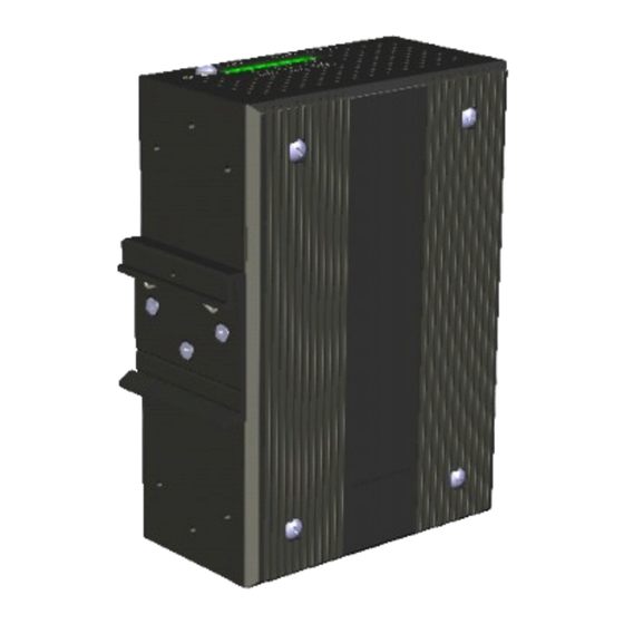
EKI-2748FI can be wall-mounted by using the included mounting kit. Then, hang on the EKI-2748FI to the nails on the wall. First, use the screws included in the package to combine the EKI-2748FI and metal mounting kit. And then you can install the device firmly via the components, please see Figure 2.5 as below. -
Page 26: Din-Rail Mounting
The DIN-rail kit is screwed on the industrial switch when out of factory. If the DIN-rail kit is not screwed on the industrial switch, please screw the DIN-rail kit on the switch first. First, hang the EKI-2748FI to the DIN-rail with angle of inclination. See Figure 2.6. Figure 2.6: Installation to DIN-rail Step 1... -
Page 27: Figure 2.7: Installation To Din-Rail Step 2
Then, hook the device over the DIN rail and let it drop down straight to slide over the rail smoothly. Figure 2.7: Installation to DIN-rail Step 2 Chapter 2... -
Page 28: Network Connection
2.4 Network Connection The EKI-2748FI has 4 x RJ-45 ports that support connection to 10 Mbps Ethernet, 100 Mbps Fast Ethernet or 1000 Mbps Gigabit Ethernet. EKI-2748FI can be connected to other hubs or switches via a twisted-pair straight-through or crossover cable up to 100m long. -
Page 29: Figure 2.9: Transceiver Inserted
Figure 2.9: Transceiver Inserted Second, insert the fiber cable of LC connector into the transceiver. Figure 2.10: LC connected to the transceiver Chapter 2... -
Page 30: Figure 2.11: Remove Lc Connector
To remove the transceiver from the slot, please follow the steps shown below: First, press the upper side of the LC connector to release from the transceiver and pull it out. Figure 2.11: Remove LC connector Second, push down the metal loop and pull the transceiver out by the plastic handle. Figure 2.12: Pull out from the slot EKI-2748FI_Manual... -
Page 31: Power Connection
2.6 Power Connection The EKI-2748FI supports dual +12 ~ 48 V and 24 V power inputs and power-fail relay output. Terminal Block Front View for Fault Alarm 24Vdc, 1A Contact Resistance Fault Alarm Application Example Figure 2.13: Pin Assignment of the Power Connector You can connect an alarm indicator, buzzer or other signaling equipment through the relay output. -
Page 32: X-Ring Application
2.7 X-Ring Application The industrial switch supports the X-Ring protocol that can help the network system recover from network connection failure within 10ms or less and make the network system more reliable. The X-Ring algorithm is similar to Spanning Tree Protocol (STP) and Rapid STP (RSTP) algorithm but its recovery time is less than STP/RSTP. -
Page 33: Coupling Ring Application
2.8 Coupling Ring Application As the illustration shown below, users can use the X-Ring groups to form a coupling ring for redundant backup. It can ensure the transmissions between X-Ring groups not to fail. The following figure is a sample of coupling ring application. Note The Ethernet switches with firmware version before v3.0 use the X-Ring function that has the limitations as follows. -
Page 34: Dual Homing Application
2.9 Dual Homing Application The Dual Homing function is to prevent the connection loss between the particular X- Ring group and the upper level/core switch. Assign one port, and only one, to be the Dual Homing port that is the backup port in each single X-Ring group. The Dual Homing function only works when the X-Ring function is active. - Page 35 Configuration Sections include: RS-232 Console Commands Set Web Browser Chapter3...
-
Page 36: Chapter 3 Configuration
Chapter 3 Configuration The EKI-2748FI can be configured via RS-232 Console or a web browser. 3.1 RS-232 Console EKI-2748FI’s RS-232 console is designed for rapidly configuring which provides the console management – CLI command. Attach the supplied cable, which one end is RJ-45 and the other end is female DB9, to connect EKI- 2748FI and your host PC or terminal. -
Page 37: Figure 3.1-3 Com Port Properties Setting
Select the appropriate COM port, and set the parameter as the figure shown below (9600 for Baud Rate, 8 for Data Bits, None for Parity, 1 for Stop Bits, and None for Flow Control). Figure 3.1-3 COM Port Properties Setting Press Enter to bring the login screen (If you can not find the login screen, press Enter one more time). -
Page 38: Figure 3.1-5 Command Line Interface
After you have logged in to the system, you will see a command prompt. To enter CLI management interface, type in “enable” command. Figure 3.1-5 Command Line Interface EKI-2748FI_Manual... -
Page 39: Commands Set
3.2 Commands Set The following table lists the CLI commands and description. 3.2.1 Commands Level Table 3.1: Command Level Modes Access Method Prompt Exit Method About This Model Begin a session with Enter logout or quit. The user commands available your switch. -
Page 40: System Commands Set
3.2.3 System Commands Set Table 3.3: System Commands Set Commands Level Description Example Show switch configuration switch>show config show config Show console information switch#show terminal show terminal Save user configuration into switch#write memory write memory permanent memory (flash rom) Configure system name switch(config)#system name xxx system name [System Name]... -
Page 41: Port Commands Set
Disable IP security function switch(config)#no security no security Disable IP security of HTTP server switch(config)#no security http no security http Disable IP security of telnet server switch(config)#no security telnet no security telnet 3.2.4 Port Commands Set Table 3.4: Port Commands Set Commands Level Description... -
Page 42: Trunk Commands Set
show interface configuration status switch(config)#interface fastEthernet 2 show interface configuration switch(config-if)#show interface configuration show interface actual status switch(config)#interface fastEthernet 2 show interface status switch(config-if)#show interface status show interface statistic counter switch(config)#interface fastEthernet 2 show interface accounting switch(config-if)#show interface accounting Clear interface accounting switch(config)#interface fastEthernet 2 no accounting information... -
Page 43: Vlan Commands Set
3.2.7 VLAN Commands Set Table 3.7: VLAN Commands Set Commands Level Description Example Enter VLAN configure mode switch#vlan database vlan database To set switch VLAN mode. switch(vlan)#vlanmode portbase Vlanmode [portbase| 802.1q | gvrp] switch(vlan)#vlanmode 802.1q switch(vlan)#vlanmode gvrp No VLAN Switch(vlan)#no vlan no vlan Ported based VLAN configuration Add new port based VALN... -
Page 44: Spanning Tree Commands Set
3.2.8 Spanning Tree Commands Set Table 3.8: Spanning Tree Commands Set Commands Level Description Example Enable spanning tree switch(config)#spanning-tree enable spanning-tree enable [0~61440] Configure spanning tree priority switch(config)#spanning-tree priority 32767 spanning-tree priority parameter [seconds] Use the spanning-tree max-age switch(config)#spanning-tree max-age 15 spanning-tree max-age global configuration command to change the interval between... -
Page 45: Igmp Commands Set
Commands Level Description Example Select QOS policy scheduling switch(config)#qos policy weighted-fair qos policy [weighted-fair|strict] Setting of QOS priority type switch(config)#qos prioritytype qos prioritytype [port-based|cos-only|tos-only|cos- first|tos-first] Configure Port-based Priority switch(config)#qos priority portbased 1 low qos priority portbased [Port] [lowest|low|middle|high] Configure COS Priority switch(config)#qos priority cos 0 middle qos priority cos [Priority][lowest|low|middle|high]... -
Page 46: Snmp Commands Set
address table 3.2.12 SNMP Commands Set Table 3.12: SNMP Commands Set Commands Level Description Example Set SNMP agent system name switch(config)#snmp system-name l2switch snmp system-name [System Name] Set SNMP agent system location switch(config)#snmp system-location lab snmp system-location [System Location] Set SNMP agent system contact switch(config)#snmp system-contact where snmp system-contact [System Contact]... -
Page 47: Port Mirroring Commands Set
[View Name] SNMPV3 agent. Excluded sub-oid 1.3.6.1 type [Excluded|Included] sub-oid [OID] 3.2.13 Port Mirroring Commands Set Table 3.13: Port Mirroring Commands Set Commands Level Description Example Set RX destination port of monitor switch(config)#monitor rx monitor rx function Set TX destination port of monitor switch(config)#monitor tx monitor tx function... -
Page 48: Tftp Commands Set
timeout global configuration command to set the server timeout. Use the 802.1x misc max request switch(config)# 8021x misc maxrequest 3 8021x misc maxrequest [number] global configuration command to set the MAX requests. Use the 802.1x misc reauth period switch(config)# 8021x misc reauthperiod 3000 8021x misc reauthperiod [sec.] global configuration command to... -
Page 49: Sntp Commands Set
[Systemlog|SMTP|Both] type Set X - ring topology changed switch(config)#event X-ring-topology-change both event X-ring-topology-change [Systemlog|SMTP|Both] event type Set port event for system log switch(config)#interface fastethernet 3 event systemlog [Link-UP|Link-Down|Both] switch(config-if)#event systemlog both Set port event for SMTP switch(config)#interface fastethernet 3 event smtp [Link-UP|Link-Down|Both] switch(config-if)#event smtp both Show event selection... -
Page 50: Lldp Command Set
Configure 1st/2nd Ring Port switch(config)#ring ringport 7 8 ring ringport [1st Ring Port] [2nd Ring Port] Configure Coupling Port switch(config)#ring couplingport 1 ring couplingport [Coupling Port] Configure Control Port switch(config)#ring controlport 2 ring controlport [Control Port] Configure Dual Homing Port switch(config)#ring homingport 3 ring homingport [Dual Homing Port]... -
Page 51: Web Browser
• Subnet Mask: 255.255.255.0 • Default Gateway: 192.168.1.254 • User Name: admin • Password: admin Open Internet Explorer and type EKI-2748FI’s IP in the Address field then press Enter to open the web login page. Figure 3.3-1 Type the address in the URL Figure 3.3-2... -
Page 52: Figure 3.3-3 Main
In the main page, you can find the tree menu structure of the Ethernet switch in the left side. Click the “+” symbol to unroll the hiding hyperlink, and click any one of the hyperlinks to open its function page. Figure 3.3-3 Main page EKI-2748FI_Manual... -
Page 53: System
3.3.1 System System Information Assign the system name, location and view the system information • System Name: Assign the name of the switch. The maximum length is 64 bytes. • System Description: Displays the description of switch. Read only cannot be modified. •... -
Page 54: Figure 3.3-5 Ip Configuration
IP Configuration Due to the foreseeable address exhausition of IPv4, the IP configuration of the Ethernet switch is designed to provide an interface for users to configure the switch running both IPv4 and IPv6 architecture. IPv4 The IPv4 tab allows users to configure the switch to receive an IP address from DHCP server or manually fill in IP Address, Subnet Mask, Gateway, IP addresses of the primary and the secondary DNS servers. -
Page 55: Figure 3.3-6 Dhcp Server - System Configuration
DHCP Server – System configuration DHCP is the abbreviation of Dynamic Host Configuration Protocol that is a protocol for assigning dynamic IP addresses to devices on a network. With dynamic addressing, a device can have a different IP address every time it connects to the network. In some systems, the device's IP address can even change while it is still connected. -
Page 56: Figure 3.3-7 Dhcp Server – Client Entries
DHCP Server – Client Entries When the DHCP server function is active, the system will collect the DHCP client information and displays it here. Figure 3.3-7 DHCP Server – Client Entries EKI-2748FI_Manual... -
Page 57: Figure 3.3-8 Dhcp Server – Port & Ip Binding
DHCP Server - Port and IP Bindings Assign the dynamic IP address to the port. When the device is connecting to the port and asks for IP assigning, the system will assign the IP address that has been assigned before to the connected device. Figure 3.3-8 DHCP Server –... -
Page 58: Figure 3.3-9 Tftp – Update Firmware
TFTP - Update Firmware Trivial File Transfer Protocol (TFTP) is a very simple file transfer protocol, with the functionality of a very basic form of FTP. It provides the functions to allow the user to update the switch firmware. Before updating, make sure you have your TFTP server ready and the firmware image is on the TFTP server. -
Page 59: Figure 3.3-10 Tftp – Restore Configuration
TFTP – Restore Configuration You can restore the configuration from TFTP server. Before doing that, you must put the image file on TFTP server first and the switch will download back the flash image. • TFTP Server IP Address: Fill in the TFTP server IP. •... -
Page 60: Figure 3.3-11 Tftp – Backup Configuration
TFTP - Backup Configuration You can save current Flash ROM value from the switch to TFTP server for restoring later. • TFTP Server IP Address: Fill in IP address of the TFTP server. • Backup File Name: Fill in the file name •... -
Page 61: Figure 3.3-12 Syslog Configuration
System Event Log – Syslog Configuration Configure the system event mode to collect system log. • Syslog Client Mode: Select the system log mode—Client Only, Server Only, or Both. • System Log Server IP Address: Assign the system log server IP. •... -
Page 62: Figure 3.3-13 Smtp Configuration
System Event Log - SMTP Configuration You can set up the mail server IP, mail account, password, and forwarded email account for receiving the event alert. • Email Alert: Enable or disable the email alert function. • SMTP Server IP: Set up the mail server IP address (when Email Alert enabled, this function will then be available). -
Page 63: Figure 3.3-14 Event Configuration
System Event Log - Event Configuration When the Syslog/SMTP checkbox is ticked, the event log will be sent to system log server/SMTP server. Also, per port log (link up, link down, and both) events can be sent to the system log server/SMTP server with the respective checkbox ticked. -
Page 64: Figure 3.3-15 Fault Relay Alarm
Fault Relay Alarm • Power Failure: Tick the checkbox to enable the function of lighting up the FAULT LED on the panel when power fails. • Port Link Down/Broken: Tick the checkbox to enable the function of lighting up FAULT LED on the panel when ports’... -
Page 65: Table 3.20: Utc Timezone
SNTP Configuration You can configure the SNTP (Simple Network Time Protocol) settings which allow you to synchronize switch clocks on the Internet. • SNTP Client: Enable/disable SNTP function to get the time from the SNTP server. • Daylight Saving Time: Enable/disable daylight saving time function. When daylight saving time is enabled, you need to configure the daylight saving time period. -
Page 66: Figure 3.3-16 Sntp Configuration
ZP5 - USSR Zone 4 +5 hours 5 pm ZP6 - USSR Zone 5 +6 hours 6 pm WAST - West Australian Standard +7 hours 7 pm CCT - China Coast, USSR Zone 7 +8 hours 8 pm JST - Japan Standard, USSR Zone 8 +9 hours 9 pm EAST - East Australian Standard GST... -
Page 67: Figure 3.3-17 Ip Security
IP Security IP security function allows the user to assign 10 specific IP addresses that have permission to access the switch through the web browser for the securing switch management. • IP Security Mode: When this option is in Enable mode, the Enable HTTP Server and Enable Telnet Server checkboxes will then be available. - Page 68 User Authentication Change web management login user name and password for the management security issue. • User Name: Key in the new user name (The default is “admin”). • Password: Key in the new password (The default is “admin”). • Confirm Password: Re-type the new password. •...
-
Page 69: Figure 3.3-19 Port Statistics
3.3.2 Port Port setting includes Port Statistics, Port Control, Port Trunk, Port Mirroring, and Rate Limiting. The user can use this interface to set the parameters and control the packet flow among the ports. Port Statistics The following information provides the current port statistics information. •... -
Page 70: Figure 3.3-20 Port Control
Port Control In Port Control, you can pull down the selection items to set the parameters of each port to control the transmitting/receiving packets. • Port: Select the port that you want to configure. • State: Current port status. The port can be set to disable or enable mode. If the port state is set as ‘Disable’, it will not receive or transmit any packet. -
Page 71: Figure 3.3-21 Aggregator Setting
Port Trunk The Link Aggregation Control Protocol (LACP) provides a standardized means for exchanging information between Partner Systems on a link to allow their Link Aggregation Control instances to reach agreement on the identity of the Link Aggregation Group to which the link belongs, move the link to that Link Aggregation Group, and enable its transmission and reception functions in an orderly manner. -
Page 72: Figure 3.3-22 2 Work Ports With Lacp Disabled
Aggregator Information When you have set up the aggregator setting with LACP disabled, you will see the local static trunk group information as below. Figure 3.3-22 2 work ports with LACP disabled Figure 3.3-23 Static trunking group of 2 ports EKI-2748FI_Manual... -
Page 73: Figure 3.3-24 Aggregator Information
When you have set up the aggregator setting of two interconnected switches with LACP enabled, you will see the respective LACP trunk group information as below. Figure 3.3-24 Aggregator Information Chapter3... - Page 74 State Activity Having set up the LACP aggregator on the tab of Aggregator Setting, you can configure the state activity for the members of the LACP trunk group. You can tick or cancel the checkbox beside the state display. When you remove the tick mark to the port and click Apply , the port state activity will change to Passive.
-
Page 75: Figure 3.3-26 Port Mirroring
Port Mirroring The Port mirroring is a method for monitoring traffic in switched networks. Traffic through ports can be monitored by one specific port which means traffic goes in or out monitored (source) ports will be duplicated into mirroring (destination) port. •... -
Page 76: Figure 3.3-27 Rate Limiting
Rate Limiting Here you can set up every port’s frame limitation type and bandwidth rate. • Ingress Limit Frame type: Select the frame type you want to filter. The frame types have 4 options for selecting: All, Broadcast/Multicast/Flooded Unicast, Broadcast/Multicast, and Broadcast only. The four frame type options are for ingress frames limitation. - Page 77 DMI (Digital Monitoring Interface) The SFP supports DMI function which allows real-time access to device operating parameters, and includes optional digital features such as soft control and monitoring of SFP I/O signals. In addition, you can set up the action of alarms and warnings by ports to manage your device. You can see the transceiver’s status by ports and set up the action when detecting the exceptional value.
-
Page 78: Figure 3.3-29 Vlan Configuration
3.3.3 Protocol The user can set the layer 2 protocol setting via this interface. VLAN configuration A Virtual LAN (VLAN) is a logical network grouping that limits the broadcast domain, which would allow you to isolate network traffic, so only the members of the same VLAN will receive traffic from the ones of the same VLAN. -
Page 79: Figure 3.3-30 Port Based Mode
VLAN configuration - Port-based VLAN Packets can go among only members of the same VLAN group. Note all unselected ports are treated as belonging to another single VLAN. If the port-based VLAN enabled, the VLAN-tagging is ignored. In order for an end station to send packets to different VLAN groups, it itself has to be either capable of tagging packets it sends with VLAN tags or attached to a VLAN-aware bridge that is capable of classifying and tagging the packet with different VLAN ID based on not only default PVID but also other information about the packet, such as the protocol. -
Page 80: Figure 3.3-31 Port Based Mode-Add Interface
Figure 3.3-31 Port based mode-Add interface • Enter the group name and VLAN ID. Add the port number having selected into the right field to group these members to be a VLAN group or remove any of them listed in the right field from the VLAN. •... -
Page 81: Figure 3.3-32 Port Based Edit/Delete Interface
Figure 3.3-32 Port Based Edit/Delete interface • Use Delete to delete the VLAN. • Use to modify group name, VLAN ID, or add/remove the members of the existing VLAN group. Edit Note Remember to execute the “Save Configuration” action, otherwise the new configuration will lose when switch power off. - Page 82 802.1Q VLAN Tagged-based VLAN is an IEEE 802.1Q specification standard. Therefore, it is possible to create a VLAN across devices from different switch venders. IEEE 802.1Q VLAN uses a technique to insert a “tag” into the Ethernet frames. Tag contains a VLAN Identifier (VID) that indicates the VLAN numbers. You can create Tag-based VLAN, and enable or disable GVRP protocol.
-
Page 83: Figure 3.3-33 802.1Q Vlan Configuration
Figure 3.3-33 802.1Q VLAN Configuration Chapter3... -
Page 84: Figure 3.3-34 Edit Group Configuration Interface
Group Configuration Edit the existing VLAN Group. • Select the VLAN group in the table list. • Click Edit Figure 3.3-34 Edit Group Configuration interface • Having clicked the Edit button, you can change the VLAN group name and VLAN ID. Figure 3.3-35 802.1Q Group Configuration-Edit •... -
Page 85: Figure 3.3-36 Rstp System Configuration Interface
Rapid Spanning Tree The Rapid Spanning Tree Protocol (RSTP) is an evolution of the Spanning Tree Protocol and provides for faster spanning tree convergence after a topology change. The system also supports STP and the system will auto-detect the connected device that is running STP or RSTP protocol. RSTP - System Configuration •... -
Page 86: Figure 3.3-37 Rstp Port Configuration Interface
RSTP - Port Configuration Here you can configure the path cost and priority of each port. • Select the port in the port column field. • Path Cost: The cost of the path to the other bridge from this transmitting bridge at the specified port. Enter a number 1 through 200,000,000. -
Page 87: Figure 3.3-38 Snmp System Configuration Interface
SNMP Configuration Simple Network Management Protocol (SNMP) is the protocol developed to manage nodes (servers, workstations, routers, switches and hubs etc.) on an IP network. SNMP enables network administrators to manage network performance, find and solve network problems, and plan for network growth. Network management systems learn of problems by receiving traps or change notices from network devices implementing SNMP. -
Page 88: Figure 3.3-39 Trap Configuration Interface
Trap Configuration A trap manager is a management station that receives the trap messages generated by the switch. If no trap manager is defined, no traps will be issued. Create a trap manager by entering the IP address of the station and a community string. - Page 89 SNMPV3 Configuration Configure the SNMP V3 function. Context Table Configure SNMP v3 context table. Assign the context name of context table. Click Apply to add context name. User Table Configure SNMP v3 user table.. • User ID: Set up the user name. •...
-
Page 90: Figure 3.3-40 Snmp V3 Configuration Interface
Figure 3.3-40 SNMP V3 Configuration interface EKI-2748FI_Manual... - Page 91 QoS Configuration Here you can configure Qos policy and priority setting, per port priority setting, COS and TOS setting. QoS Policy and Priority Type • Qos Policy: Select the QoS policy rule. Use an 8,4,2,1 weighted fair queuing scheme: The switch will follow 8:4:2:1 rate to process priority queue from High to lowest queue.
-
Page 92: Figure 3.3-41 Qos Configuration Interface
Figure 3.3-41 QoS Configuration interface EKI-2748FI_Manual... -
Page 93: Table 3.21: Igmp Types
IGMP Configuration The Internet Group Management Protocol (IGMP) is an internal protocol of the Internet Protocol (IP) suite. IP manages multicast traffic by using switches, routers, and hosts that support IGMP. Enabling IGMP allows the ports to detect IGMP queries, report packets, and manage IP multicast traffic through the switch. - Page 94 X-Ring X-Ring provides a faster redundant recovery than Spanning Tree topology. The action is similar to STP or RSTP, but the algorithms between them are not the same. In the X-Ring topology, each switch should be enabled with the X-Ring function and two ports of each switch should be configured as the member ports in the ring.
-
Page 95: Figure 3.3-43 X-Ring Interface
Figure 3.3-43 X-ring interface Note To enable the X-Ring function, users must disable the RSTP first. The X-Ring function and RSTP function cannot both be activated on a single switch. Remember to execute the “Save Configuration” action, otherwise the new configuration will lose when switch powers off. - Page 96 LLDP Configuration LLDP (Link Layer Discovery Protocol) function allows the switch to advertise its information to other nodes on the network and store the information it discovers. • LLDP Protocol: Disable or enable the LLDP function. • LLDP Interval: Set the interval of learning the information in seconds. •...
-
Page 97: Figure 3.3-45 802.1X/Radius System Configuration
3.3.4 Security In this section, you can configure 802.1x and MAC address table. 802.1X/Radius Configuration 802.1x is an IEEE authentication specification which prevents the client from connecting to a wireless access point or wired switch until it provides authority, like the user name and password that are verified by an authentication server (such as RADIUS server). -
Page 98: Figure 3.3-46 802.1X/Radius - Port Setting
802.1x/Radius - Port Configuration You can configure the 802.1x authentication state for each port. The state provides Disable, Accept, Reject, and Authorize. • Reject: The specified port is required to be held in the unauthorized state. • Accept: The specified port is required to be held in the Authorized state. •... -
Page 99: Figure 3.3-47 802.1X/Radius - Misc Configuration
802.1X/Radius - Misc Configuration • Quiet Period: Set the period which the port doesn’t try to acquire a supplicant. • TX Period: Set the period the port waits for retransmit next EAPOL PDU during an authentication session. • Supplicant Timeout: Set the period of time the switch waits for a supplicant response to an EAP request. -
Page 100: Figure 3.3-48 Static Mac Addresses Interface
MAC Address Table Use the MAC address table to ensure the port security. You can add a static MAC address; it remains in the switch's address table, regardless of whether the device is physically connected to the switch. This saves the switch from having to re-learn a device's MAC address when the disconnected or powered-off device is active on the network again. -
Page 101: Figure 3.3-49 Mac Filtering Interface
MAC Address Table - MAC Filtering By filtering MAC address, the switch can easily filter the pre-configured MAC address and reduce the un- safety. You can add and delete filtering MAC address. Figure 3.3-49 MAC Filtering interface • MAC Address: Enter the MAC address that you want to filter. •... -
Page 102: Figure 3.3-50 All Mac Address Interface
Figure 3.3-50 All MAC Address interface EKI-2748FI_Manual... -
Page 103: Figure 3.3-51 Multicast Filtering Interface
MAC Address Table—Multicast Filtering Multicasts are similar to broadcasts, they are sent to all end stations on a LAN or VLAN. Multicast filtering is the system by which end stations only receive multicast traffic if they register to join specific multicast groups. -
Page 104: Figure 3.3-52 Factory Default Interface
Factory Default Reset switch to default configuration. Tick the check boxes to keep the current IP address, user name and password before reset. Click Reset to reset all configurations to the default value. Figure 3.3-52 Factory Default interface EKI-2748FI_Manual... -
Page 105: Figure 3.3-53 Save Configuration Interface
Save Configuration Save all configurations that you have made in the system. To ensure the all configuration will be saved, click Save to save the all configuration to the flash memory. Figure 3.3-53 Save Configuration interface Chapter3... -
Page 106: Figure 3.3-54 System Reboot Interface
System Reboot Reboot the switch in software reset. Click Reboot to reboot the system. Figure 3.3-54 System Reboot interface EKI-2748FI_Manual... - Page 107 Chapter3...
-
Page 108: Troubleshooting
Troubleshooting EKI-2748FI_Manual... -
Page 109: Chapter 4 Troubleshooting
Chapter 4 Troubleshooting Verify that you are using the included or appropriate power cord/adapter. Don’t use the power adaptor with DC output voltage higher than the power rating of the device. Otherwise, the device will burn down. Select the proper UTP cable to construct the network. Use unshielded twisted-pair (UTP) or shield twisted-pair (STP) cable for RJ-45 connections: 100Ω... - Page 110 Pin Assignments & Wiring EKI-2748FI_Manual...
-
Page 111: Appendix A Pin Assignments & Wiring
Appendix A Pin Assignments & Wiring It is suggested to adopt ELA/TIA as the wiring of the RJ-45. Figure A.1: RJ-45 Pin Assignments Figure A.2: EIA/TIA-568B Figure A.3: EIA/TIA-568A... -
Page 112: Figure A.4: Db 9-Pin Female Connector
Figure A.4: DB 9-pin female connector DB9 Connector RJ-45 Connector 1 Orange/White 2 Orange 3 Green/White 4 Blue 5 Blue/White 6 Green 7 Brown/White 8 Brown EKI-2748FI_Manual... - Page 114 Compatible SFP Transceivers EKI-2748FI_Manual...
- Page 115 Appendix B Compatible SFP Transceivers The table below shows compatible SFP transceivers for EKI-2748FI. Transmission Item Brand Part Number Mode Distance AVAGO AFBR-5710PZ 550m APAC LM28-C3S-TC-N 550m Multi-mode HOATECH HTI8512-X5ATO 550m SPACE SHUTTLE S56L-S85-6L-N 550m SP-GB-LX 10km LuminentOIC SP-GB-ELX 20km...
Need help?
Do you have a question about the EKI-2748FI and is the answer not in the manual?
Questions and answers