
Related Manuals for Grizzly G4791


Summary of Contents for Grizzly G4791
- Page 1 MODEL G4791 12" x 39" LARGE COMBO LATHE/MILL OWNER'S MANUAL WARNING: NO PORTION OF THIS MANUAL MAY BE REPRODUCED IN ANY SHAPE OR FORM WITHOUT THE WRITTEN APPROVAL OF GRIZZLY INDUSTRIAL, INC.
-
Page 3: Table Of Contents
SECTION 1: SAFETY ... 7 SECTION 2: CIRCUIT REQUIREMENTS ... 11 SECTION 3: SETUP ... 12 SECTION 4: MILL OPERATIONS ... 20 SECTION 5: LATHE OPERATIONS ... 27 Table of Contents SECTION 6: ACCESSORIES ... 50 SECTION 7: MAINTENANCE ... 53 SECTION 8: SERVICE ... -
Page 4: Introduction
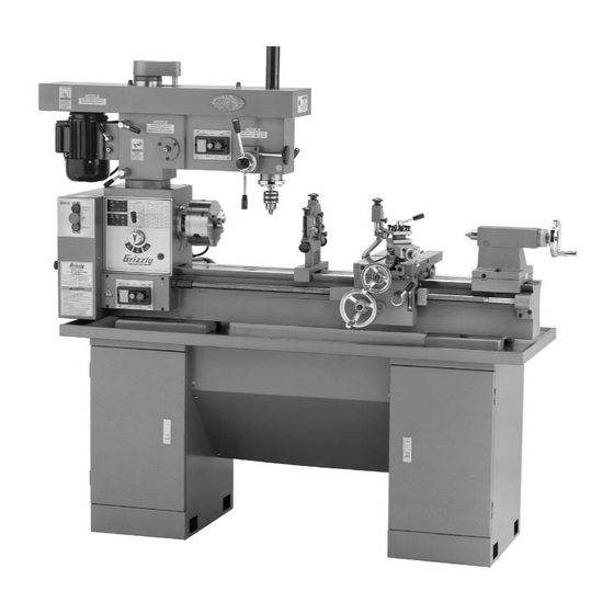
INTRODUCTION Functional Overview Foreword www.grizzly.com Contact Info... - Page 5 Identification Figure 1.
-
Page 6: Machine Data Sheet
Machine Data Sheet Customer Service #: (570) 546-9663 · To Order Call: (800) 523-4777 · Fax #: (800) 438-5901 MODEL G4791 12" X 39" LARGE COMBO LATHE/MILL Product Dimensions: Weight... 1110 lbs. Length/Width/Height... 69 x 25 x 69 in. Foot Print (Length/Width)... 56 x 19-1/2 in. - Page 7 No. Of Change Gears... 14 Swing Over Bed... 12 in. Swing Over Saddle... 6-7/8 in. Dist. Between Centers...39 in. Spindle Bore...1-1/2 in. Lathe Spindle Taper...MT#5 Mill Info Drill Press Taper... MT#3 Mill Drill Spindle Travel...5 in. Mill Drill Swing... 21 in.
- Page 8 Construction Bed Const... Hardened and Ground Cast Iron Headstock Const... Cast Iron Body Const... Cast Iron Frame Const...Cast Iron Headstock Gears Const...Steel Stand Const...Cast Iron Paint... Epoxy Other Bed Width...6-1/8 in. Floor To Center Height...43 in. Lead Screw Diameter...0.950 in. Lead Screw TPI...8 Lead Screw Length...
-
Page 9: Safety Instructions For Machinery
Safety Instructions for Machinery... -
Page 11: Additional Safety Instructions For Mills
Additional Safety Instructions For Mills UNDERSTANDING CONTROLS. SAFETY ACCESSORIES. WORK HOLDING. CHUCK KEY SAFETY. SPINDLE SPEEDS. POWER DISRUPTION. STOPPING SPINDLE. CLEAN-UP. BE ATTENTIVE. Like all machinery there is potential danger when operating this machine. Accidents are frequent- ly caused by lack of familiarity or failure to pay attention. Use this mill with respect and caution to reduce the risk of operator injury. -
Page 12: Additional Safety Instructions For Lathes
Additional Safety Instructions for Lathes UNDERSTANDING CONTROLS. CLEANING MACHINE: USING CORRECT TOOLING: ELIMINATING A PROJECTILE HAZARD: SECURING A WORKPIECE: AVOIDING OVERLOADS: AVOIDING ENTANGLEMENT INJURIES: No list of safety guidelines can be complete. Every shop environment is different. Always con- sider safety first, as it applies to your individual working conditions. Use this and other machin- ery with caution and respect. -
Page 13: Section 2: Circuit Requirements
SECTION 2: CIRCUIT REQUIREMENTS 220V Operation Serious personal injury could occur if you connect the machine to power before com- pleting the setup process. DO NOT connect the machine to the power until instructed later in this manual. Electrocution or fire could result if machine is not grounded and installed in compliance with electrical... -
Page 14: Section 3: Setup
Wear safety glasses dur- ing the entire setup pro- cess! The Model G4791 is a heavy machine. Serious personal injury may occur if safe moving methods are not used. To be safe, get assistance and use power equipment rated for at least 2000 lbs. - Page 15 Inventory Note: If you can't find an item on this list, check the mounting location on the machine or examine the packaging materials carefully. Occasionally we pre-install certain components for shipping purposes. Inventory: (Figures 3–4) Figure 3. Figure 4. SUFFOCATION HAZARD! Immediately discard all plas- tic bags and packing materi- als to eliminate choking/suf-...
-
Page 16: Site Considerations
Clean Up Figure 5 For optimum performance, clean all moving parts or sliding contact surfaces. Gasoline and petroleum products have low flash points and can explode or cause fire if used to clean machinery. NOT use these products to clean the machinery. Many cleaning solvents toxic Minimize your risk by only... - Page 17 Placement & Assembly The Model G4791 is a heavy machine. Serious personal injury may occur if safe moving methods are not used. To be safe, get assistance and use power equipment rated for at least 2000 lbs. to move the shipping crate and remove the machine from the crate.
-
Page 18: Mounting To Shop Floor
Figure 9 Note: It may be necessary to slightly re- position the cabinets and chip pan during this step. Figure 9. Note: Re-check the bedway for levelness after the first 24 hours, the first two weeks, then annually after that. Mounting to Shop Floor Bolting to Concrete Floors... -
Page 19: Test Run
Using Machine Mounts Figure 11 NOTICE We strongly recommend securing your machine to the floor if it is hardwired to the power source. Consult with your electrician to ensure compliance with local codes. Check Gearbox Oil Lubrication GEARBOXES MUST BE FILLED WITH OIL! NO OIL SHIPPED WITH MACHINE! Requires ISO 68... - Page 20 Before starting the machine, make sure you have performed the preceding assembly and adjustment instructions, and you have read through the rest of the manual and are familiar with the various functions and safety features on this machine. Failure to follow this warning could result in serious personal injury or even death! Figure 13...
-
Page 21: Recommended Adjustments
Spindle Break-In NOTICE Successfully complete all of the spindle break-in steps for both the lathe and mill to avoid rapid deterioration of the spindle bearings and other related parts. To perform the spindle break-in for this machine: Lubrication Page 54 Setting Mill Speed Steps 4–6... -
Page 22: Section 4: Mill Operations
WE STRONGLY RECOMMEND that you read books, trade magazines, or get formal training before beginning any projects. Regardless of the content in this section, Grizzly Industrial will not be held liable for accidents caused by lack of training. Basic Mill Controls Figures 14–15... -
Page 23: Figure
N. Main Power EMERGENCY Button: O. Main Power Lamp: P. Motor Position Crank: Turning the mill and lathe ON at the same time presents an entanglement hazard and could cause serious personal injury or damage to the machine. To prevent this condition, DO NOT have the mill and lathe running at the same time. -
Page 24: Figure
Table Movement Figure 16 Figure 16. Handwheel Dial Increments twice Figure 17 Figure 17. Head Movement Rotating the Mill Head Resolution Figure 18. Elevating the Mill Head Unexpected head movement when the mill is running can cause the cutting tool to move into the operator or damage the workpiece. -
Page 25: Figure 19
Setting Mill Speed Calculating Mill Spindle Speed Figure 19 Note: Cutting speed is the rotational speed that the cutter moves over/into the workpiece, and is expressed in surface feet per minute (SFM). Cutting Speeds for High Speed Steel (HSS) Cutting Tools Note: For carbide cutting tools, double the cutting speed. - Page 26 Note: This chart is also on the front of the machine. In most cases, the calculated spindle speed will be between the available speeds. Use your best judgement when choosing either a higher or lower spindle speed. Example with HSS Cutting Tool Step 1: Figure 19 Page 23...
- Page 27 Quill Downfeed Figure 23 Figure 23. To use the downfeed controls: Note: It may be necessary to move the quill slightly up or down to push the downfeed selector knob all the way in. Note: Since the spring that automatically raises the quill is fairly strong, we recommend raising the quill in a controlled manner by hand to avoid premature wear to the mecha-...
- Page 28 Unloading Tooling With the Drawbar Unloading Tooling With the Drift Key Figure 25 Figure 25. Cutting tools are sharp and can quickly injure your hands. Always protect your hands when handling cutting tools.
-
Page 29: Section 5: Lathe Operations
WE STRONGLY RECOMMEND that you read books, trade magazines, or get formal training before beginning any projects. Regardless of the content in this section, Grizzly Industrial will not be held liable for accidents caused by lack of training. Basic Lathe Controls Figures 26–28... - Page 30 H. Change Gear Cabinet: Main Power ON Button: Main Power EMERGENCY Button: Carriage Figure 27. K. Table (Cross Feed) Handwheel: Compound Slide Mounting Bolt: M. Compound Slide Rotational Adjustment Nut: N. 4-Way Tool Post: O. Compound Slide Handwheel: P. Thread Dial: Q.
-
Page 31: Step
Mounting/Removing Chuck or Faceplate ACCESSORIES Page 50 Tools Needed Mounting a Chuck or Faceplate Figure 29 Figure 29. Debris or grit on the mating surfaces will not allow the chuck or faceplate to evenly seat onto the spindle back plate. This con- dition could allow the chuck or faceplate to vibrate loose during use and cause serious personal injury. -
Page 32: Jaw Chuck
Figure 29 PINCH HAZARD! Get assistance and pro- tect your hands and the precision ground bedways with plywood or a chuck cradle when removing the lathe chuck! The heavy weight of a falling chuck can cause serious injury. 3-Jaw Chuck Figure 31 Figure 31. - Page 33 Tools Needed Mounting Workpiece in 3-Jaw Chuck Securely workpiece and remove the chuck key! Thrown objects from a lathe can cause serious injury or death to the operator and to bystanders many feet away. Removing Jaws from 3-Jaw Chuck Note: Each jaw will move until it becomes loose from the scroll gear threads, then it can be removed by hand.
- Page 34 Installing Jaws into 3-Jaw Chuck Figure 33 Figure 33. Steps 4–5 It is important to follow these points when replacing jaws in your 3-jaw chuck: 4-Jaw Chuck Page 29 Tools Needed To mount a workpiece in the 4-jaw chuck:...
- Page 35 Figure 34 Figure 34. Figure 35 Figure 35. Always use a low spindle speed when machining non-cylindrical or off-center workpieces to avoid ejecting the workpiece from the holding device at a high rate of speed. Failure to heed this warning could lead to serious personal injury, death or property damage.
- Page 36 Centers Figure 37 Figure 37. Figure 38 Figure 38. ACCESSORIES Page 50 Using a Dead Center in the Spindle Note: Hold onto the center as you tap it loose to avoid dropping it and damaging the tip or the bedways. Figure 38...
-
Page 37: Offsetting Tailstock
Using a Dead Center in the Tailstock Note: For stability and accuracy, the tailstock quill with the dead center mounted should protrude between ⁄ " and 1 Note: The force against the mounted workpiece will fully seat the center's taper. However, do not overly force the center into the workpiece—this will make removing the center very difficult. -
Page 38: Aligning Tailstock
Aligning Tailstock To align the tailstock: Page 16 Note: If the tailstock is slightly out of align- ment by a few thousands of an inch, the center drill will find the center point during the drilling process. If the tailstock appears gross- ly out of alignment, move the tailstock until it appears to be centered (refer to the previous subsection for detailed instructions). -
Page 39: Drilling With Tailstock
thinner Drilling with away Tailstock half Figure 43 Note: Refer to Offsetting Tailstock on Page 35 for making adjustments to the tailstock position. Figure 44 Figure 43. Figure 44. -
Page 40: Follow Rest
Follow Rest Figure 45. Tools Needed To use the follow rest: Tip: To further avoid deflection of the workpiece during setup, use the method Figure 45 shown in Figure 46. The test indicator is set directly opposite the brass fingers on the workpiece, then the brass finger is moved into the workpiece until the dial on the indi- cator begins to move. -
Page 41: Steady Rest
Steady Rest Tools Needed To use the steady rest: Figure 47 Figure 47. Figure 48 Figure 48. Note: See the Tip on Page 38 for a method to further minimize deflection during steady rest setup. -
Page 42: Compound Slide
Carriage Handwheel Dial Increments Figure 49 Figure 49. Figure 50 Figure 50. Cross Slide (Table) Resolution Handwheel Dial Increments Compound Slide Handwheel Dial Increments Figure 51 Figure 51. Resolution twice Resolution... -
Page 43: Tool Post
Tool Post Figure 52 Figure 52. Tools Needed To load and use the 4-way tool post: Step 1 When securing a tool into the tool post, always remember these rules: Figure 53 Figure 53. - Page 44 Setting Lathe Speed Calculating Correct Spindle Speed Figure 54 Note: Cutting speeds are expressed in sur- face feet cut per minute (SFM). Recommended Cutting Speeds Rough Cuts Note: These values are based on HSS cutting tools. For carbide cutting tools, double the aver- age speed.
- Page 45 Note: Your lathe/mill ships with three V-belts of varying length for the lathe spindle speed configuration: 1) 26", 2) 28", and 3) 29". Use your best judgement when deciding which length of V-belt to use for each pulley con- nection.
-
Page 46: Setting Feed Rate
Example Step 1: Figure 54 Step 2: Step 3: Step 4: Step 5: Figure 57 Figure 57. Setting Feed Rate Figure 55 Figure 58. Note: The feed rate configuration chart is also on the inside of the change gear cabinet door. Figure 58... - Page 47 "II" position, point the arrow at 2/HI (high). Attempting to move the feed rate range lever when the lathe is running will damage the internal gears of the power feed mecha- nism and will void the warranty. NEVER attempt to move the feed rate range lever when the lathe is running.
- Page 48 Configure Change Gears Tools Needed To configure the change gears: Figure 60 Note: Your lathe/mill is shipped with the fol- lowing change gears installed: Figure 60. Figure 58 Page 44 Column D Note: Before you install or store the gears,...
- Page 49 Change Gear "B" or "C" Note: Be sure to retain the T-nut behind the pivot arm that the bolt threads into. Change Gear "D" Example of Setting Feed Rate Step 1: Figure 58 Step 2: 2/HI Step 3: Page 44...
-
Page 50: Threading Controls
Threading Controls Half-Nut Lever Figure 61 Figure 61. Thread Dial Figure 62. NOTICE Use lower spindle speeds (RPM) when threading. A slower RPM will give you more time to engage/disengage the half-nut, especially if threading over a short distance or threading up to a shoulder. Figure 62... - Page 51 Follow these rules and refer to the chart in Figure 63 when using the thread dial: Note: The thread pitch of the longitudinal leadscrew is 8. Figure 64 Thread Pitch Thread Dial Setting Figure 63. Figure 64. Note: The thread dial is not used when cutting metric threads.
-
Page 52: Section 6: Accessories
SECTION 6: ACCESSORIES H8257—Primrose Armor Plate with Moly-D Machine and Way Oil 1 Quart S. Balolia – President Figure 65. G9849—Magnetic Base/Dial Indicator Combo Figure 66. G1076—52-PC. Clamping Kit, Figure 67. G1070—MT3 Live Center Set Figure 68. ⁄ " T-Nut... - Page 53 T10063—Milling Vise 12 ⁄ " x 6 T10064—Milling Vise 17 ⁄ " x 8 Figure 69. H2987—½" Bent Lathe Dog Figure 70. ⁄ " H7540—Metalworking Kit No. 1 ⁄ " Figure 71. G9256—6" Dial Caliper G9257—8" Dial Caliper G9258—12" Dial Caliper...
- Page 54 H6879—Lathe Operation & Maintenance Book H6880—Turret Mill Operation G5053—The Home Machinist's Handbook Figure 73. H2670—HSS Square Tool Bits, Figure 74. H2677—6" Precision Rotary Table Figure 75. H5680—Glanze 7-Pc. Insert Turning Tool Set H5682—10-Pack of Carbide Inserts ⁄ " x ⁄...
-
Page 55: Section 7: Maintenance
Annually: Page 56 DO NOT use compressed air to blow away chips from the lathe to avoid the risk of flying metal debris injuring yourself or oth- ers, or driving the chips deep into the lathe mechanisms resulting in damage or prema- ture wear. - Page 56 Daily Lubrication Procedures Figure 77 Description Figure Follow reasonable lubrication practices as outlined in this manual for your lathe. Failure to do so could lead to premature failure of your lathe and will void the warranty. Lubrication Figures 78–90 Lubricant Figure 77.
- Page 57 Figure 78. Figure 82. Figure 79. Figure 83. Figure 84. Figure 80. Figure 85. Figure 81.
- Page 58 Figure 86. Figure 90. Checking/Adding Lathe Gearbox Oil Reservoir Lubricant Frequency Figure 87. Tools Needed To check and add oil to the reservoir: Figure 91 Figure 88. Figure 91. Figure 89.
- Page 59 Figure 92 Figure 92. NOTICE The lathe gearbox oil must be changed after the first three months of operation, then annually after that. Semi-Annual Lubrication Tools Needed To perform the semi-annual procedure: Figure 93 Figure 93. Note: If necessary to pry the end cap off,...
- Page 60 Figures 94–95 Figure 94. Figure 95. Note: To avoid damage to the bevel gears, make sure the teeth of the bevel gears mesh while inserting the end cap and gear without forcing them into the head. Figure 96 Figure 96. Figure 97 Figure 97.
- Page 61 Note: If you have difficulty removing the fill plug, do not remove the drain plug to drain the reservoir until you can successfully remove the fill plug. This way you can still operate the lathe until the difficulty is resolved. Figure 92...
- Page 62 Tools Needed To adjust the motor V-belt tension: Figure 100 Note: Moving the motor toward the lathe head will reduce V-belt tension. Conversely, pulling the motor away from the lathe head will increase V-belt tension. Figure 100. Figure 101 Figure 101.
-
Page 63: Section 8: Service
SECTION 8: SERVICE Troubleshooting Motor & Electrical Page 73... - Page 64 Mill Operation Page 23 Page 23 Page 64 Page 54 Page 64 Page 23 Page 64...
- Page 65 Lathe Operations Page 64 Page 41 Page 64 Page 64 Page 65 Page 64 Page 64 Page 65 Page Page Page 36...
-
Page 66: Adjusting Gibs
Adjusting Gibs NOTICE Excessively loose gibs may cause poor workpiece finishes, and may cause undue wear of the sliding surfaces. Over-tightening the gibs may cause premature wear of these sliding surfaces. Saddle and Table Gibs Tools Needed To adjust the saddle and table gibs: Figure 102. -
Page 67: Tailstock Gib
Note: Turning the screws clockwise will tighten the gib, and turning them counter- clockwise will loosen the gib. Steps 2–4 Tailstock Gib Tools Needed To adjust the tailstock gib: Note: Turning the set screws clockwise will tighten the gib, and turning them counter- clockwise will loosen the gib. -
Page 68: Adjusting Half-Nut
Adjusting Half-Nut Tools Needed To adjust the half-nut: Note: Turn the screws clockwise to tighten the gib, and counterclockwise to loosen it. Figure 106. Replacing Shear Figure Figure 107. Tools Needed To replace a shear pin: Pins Figure 107... - Page 69 Lathe Bearing Preload Note: Lathe spindle end-play can be felt when attempting to move the spindle toward and away from the headstock. Tools Needed To adjust the lathe spindle bearing preload: Figure 108 Figure 108. Note: You may have to tap on the outboard...
- Page 70 NOTICE Adjusting the lathe spindle preload is a fair- ly complex procedure that requires precise measurements. If you are not comfortable performing this procedure, get assistance from an experienced professional. Figure 110 Figure 110. Note: While tightening the spanner nut, rock...
- Page 71 Figure 111. Note: It may only be possible to partially engage a lock washer tang with the spanner nut, which will be sufficient. To confirm that the spindle bearings are cor- rectly preloaded: Figure 111 Step 10...
-
Page 72: Section 9: Wiring
GROUNDED CIRCUIT. WARNING! SHOCK HAZARD! Disconnect power before working on wiring. MOTOR WIRING. 5. EXPERIENCING DIFFICULTIES. NOTICE The photos and diagrams included in this section are best viewed in color. You can view these pages in color at www.grizzly.com. -
Page 73: Wiring Overview
Page 73 Electrical Ground Main 220 VAC Power 6-20 Plug Switch (as recommended) Page 72 Lathe Motor Wiring Overview Mill Motor Page 72 READ ELECTRICAL SAFETY Mill Switch Page 73 Page 73 Lathe Switch Page 73 ON PAGE 70! - Page 74 Electrical Component Wiring Diagrams Figure 112. Page 73 Page 73 Figure 113. READ ELECTRICAL SAFETY ON PAGE 70! Electrical Box Contactor Tengen CJX8-16 Lamp STOP 220 VAC 6-15 Plug (as recommended)
- Page 75 Electrical Component Wiring Diagrams Figure 114. Page 72 Mill Switch (as viewed from behind) Figure 115. Page 72 Lathe Switch (as viewed from behind) READ ELECTRICAL SAFETY ON PAGE 70! Figure 116. Mill Motor Figure 117. Lathe Motor...
-
Page 76: Section 10: Parts
SECTION 10: PARTS Mill Head Breakdown... - Page 77 Mill Head Parts List REF PART # DESCRIPTION P4791001 SPANNER NUT M30-1.5 P4791002 BEVEL GEAR 46T P4791003 SPACER P8107 THRUST BEARING 8107 P4791005 LEADSCREW NUT BRACKET PSB13M CAP SCREW M8-1.25 X 30 P4791007 ELEVATION LEADSCREW NUT PK60M KEY 8 X 8 X 15 P4791009 MILL COLUMN P4791010...
- Page 78 Downfeed Breakdown REF PART # DESCRIPTION P4791101 SPRING COVER P4791102 COILED SPRING 0.8 X 20 X 1000 P4791103 SPRING SEAT PS17M PHLP HD SCR M4-.7 x 6 P4791105 GEAR SHAFT 18T PK99M KEY 6 X 6 X 15 P4791107 PIN 5 X 28 P4791108 WORM SEAT P4791109...
- Page 79 Mill Motor Breakdown REF PART # DESCRIPTION P4791201 MOTOR PULLEY PK99M KEY 6 X 6 X 15 PSS05M SET SCREW M5-.8 X 10 PB85M HEX BOLT M8-1.25 X 18 P4791205 MILL MOTOR 3/4HP 220V 1-PH 205-1 P4791205-1 CAPACITOR COVER 205-2 P4791205-2 S CAPACITOR 75M 250V 1-1/4 X 3-1/8 205-3 P4791205-3 R CAPACITOR 16M 450V 1-5/8 X 2-7/8...
-
Page 80: Tailstock Breakdown
Tailstock Breakdown REF PART # DESCRIPTION P4791301 TALESTOCK GIB P4791302 KNOB M6-1 X 36 P4791303 HANDLE M6-1 X 40 P4791304 HANDLE HUB P4791305 GRADUATED LABEL P4791306 SPECIAL T-NUT P4791307 TAILSTOCK QUILL P4791308 COLLAR PSS05M SET SCREW M5-.8 X 10 P4791310 LOCK PLUNGER P4791311 KNOB... -
Page 81: Bed Breakdown
Bed Breakdown... -
Page 82: Bed Parts List
REF PART # DESCRIPTION P4791401 P4791402 TABLE P4791403 TABLE GIB P4791404 LOCK PLUNGER P4791405 BRACKET P4791406 SADDLE PSB49M CAP SCREW M6-1 X 60 P4791408 TAPER PIN 5 X 45 P4791409 LOCK PLUNGER PSS84M SET SCREW M10-1.5 X 35 P4791411 WIPER RIGHT REAR PS09M PHLP HD SCR M5-.8 X 10 P4791413... - Page 83 PART # DESCRIPTION P4791501 CHANGE GEAR 20T 501A P4791501A CHIP PAN * P4791502 CHANGE GEAR 35T P4791503 SPLINE P4791504 SHAFT PEC10M E-CLIP 9MM P4791506 CHANGE GEAR 26T P4791507 SPLINE PK98M KEY 3 X 3 X 16 PN02M HEX NUT M10-1.5 PW04M FLAT WASHER 10MM P4791511...
- Page 84 Lathe Head Breakdown...
- Page 85 Lathe Head Parts List REF PART # DESCRIPTION P4791572 LATHE SWITCH ASSEMBLY 572-1 P479174-1 ELECTRICAL BOX 572-2 P479174-2 SWITCH COVER 572-3 PS36 PHLP HD SCR 10-24 X 2-1/2 572-4 P479174-4 FWD/REV SWITCH 572-5 P479174-5 ON SWITCH 572-6 P479174-6 OFF SWITCH...
- Page 86 P4791704 STAR GRIP KNOB 8 X 32 P4791705 BUSHING P4791706 DOOR P4791707 BUTT HINGE P4791708 LATHE DRIVE SYSTEM CABINET P4791709 PIVOT PLATE P4791710 BUSHING PFH05M FLAT HD SCR M5-.8 X 12 P4791712 TENSION SPRING 2 X 12 X 61.5 REF PART #...
- Page 87 Lathe Motor Breakdown REF PART # DESCRIPTION PB07M HEX BOLT M8-1.25 X 25 PK41M KEY 8 X 8 X 40 P4791803 MOTOR 1-1/2HP 220V 1-PH 803-1 P4791803-1 CAPACITOR COVER 803-2 P4791803-2 S CAP. 150M 250V 1-1/4 X 3-1/8 803-3 P4791803-3 R CAP.
- Page 88 Steady Rest Breakdown PART # DESCRIPTION P4791340 STEADY REST ASSEMBLY 340-1 PSW03-1 KNOB 340-2 P4791340-2 TAPER PIN 3 X 22 340-3 P4791340-3 ADJUSTMENT BOLT 340-4 P4791340-4 ADJUSTMENT BOLT SLEEVE 340-5 PSS01M SET SCREW M6-1 X 10 340-6 P4791340-6 KNURLED SCREW 340-7 P4791340-7 BOTTOM FRAME...
-
Page 89: Compound Slide Breakdown
Compound Slide Breakdown REF PART # DESCRIPTION P4791900 COMPLETE COMPOUND ASSY P4791901 LEADSCREW NUT P4791902 COMPOUND SLIDE LEADSCREW PK134M KEY 4 X 4 X 14 P4791904 LEADSCREW BRACKET P4791109 BALL OILER 8MM PSB01M CAP SCREW M6-1 X 16 P4791907 GRADUATED DIAL P4791908 SPRING INDICATOR P4791909... -
Page 90: Accessories Breakdown
Accessories Breakdown PART # DESCRIPTION 1101 P47911101 4-JAW CHUCK ASSY 8" 1101-1 P47911101-1 4-JAW CHUCK 8" 1101-2 P47911101-2 JAW SET FOR 4-JAW CHUCK 1102 P47911102 3-JAW CHUCK ASSY 6" 1103 P47911103 FACEPLATE 8" 1104 P47911104 3-JAW CHUCK KEY 1105 P47911105 4-JAW CHUCK KEY 1106 P47911106... -
Page 91: Label Placement
MUST maintain the original location and readability of the labels on the machine. If any label is removed or becomes unreadable, REPLACE that label before using the machine again. Contact Grizzly at (800) 523-4777 or www.grizzly.com to order new labels. Label Placement... -
Page 95: Warranty And Returns
WARRANTY AND RETURNS...
Need help?
Do you have a question about the G4791 and is the answer not in the manual?
Questions and answers