Grizzly G4000 Owner's Manual
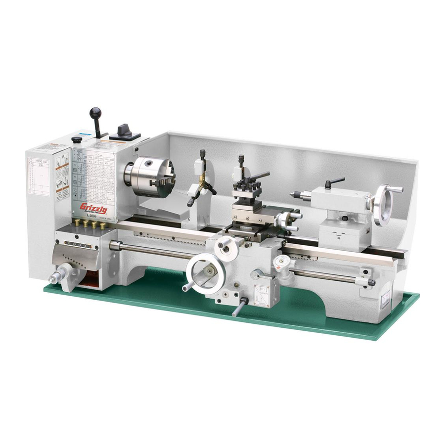
9" x 19" bench lathe
Hide thumbs
Also See for G4000:
- Instruction manual (57 pages) ,
- Parts list (24 pages) ,
- Owner's manual (76 pages)
Table of Contents
Advertisement
Quick Links
MODEL G4000
9" X 19" BENCH LATHE
OWNER'S MANuAL
Copyright © ApriL, 2009 By grizzLy industriAL, inC., rEVisEd MArCh, 2013 (tr)
WARNiNG: NO pORTiON Of THiS MANuAL MAy BE REpRODuCED iN ANy SHApE
OR fORM WiTHOuT THE WRiTTEN AppROvAL Of GRizzLy iNDuSTRiAL, iNC.
(For ModELs MAnuFACturEd sinCE 8/09) #ts11444 printEd in ChinA
Advertisement
Table of Contents

Related Manuals for Grizzly G4000


Summary of Contents for Grizzly G4000
- Page 1 9" X 19" BENCH LATHE OWNER'S MANuAL Copyright © ApriL, 2009 By grizzLy industriAL, inC., rEVisEd MArCh, 2013 (tr) WARNiNG: NO pORTiON Of THiS MANuAL MAy BE REpRODuCED iN ANy SHApE OR fORM WiTHOuT THE WRiTTEN AppROvAL Of GRizzLy iNDuSTRiAL, iNC.
- Page 2 This manual provides critical safety instructions on the proper setup, operation, maintenance, and service of this machine/tool. Save this document, refer to it often, and use it to instruct other operators. Failure to read, understand and follow the instructions in this manual may result in fire or serious personal injury—including amputation, electrocution, or death.
-
Page 3: Table Of Contents
Table of Contents iNTRODuCTiON ..........2 SECTiON 5: ACCESSORiES ......43 Manual Accuracy ........... 2 SECTiON 6: MAiNTENANCE ......47 Contact info............ 2 schedule ............47 Machine description ........2 Cleaning & protecting ........47 identification ........... 3 Lubrication ........... 47 Machine data sheet ........ -
Page 4: Introduction
Any updates to your model knurling, and threading. there are a wide variety of machine will be reflected in these documents of tools and workpiece holding devices available as soon as they are complete. -
Page 5: Identification
WE STRONGLy RECOMMEND that you read books, review industry trade magazines, or get formal training before beginning any projects. Regardless of the content in this section, Grizzly industrial will not be held liable for accidents caused by lack of training. -
Page 6: Machine Data Sheet
Machine Data Sheet MACHINE DATA SHEET Customer Service #: (570) 546-9663 · To Order Call: (800) 523-4777 · Fax #: (800) 438-5901 MODEL G4000 9" X 19" BENCH LATHE Product Dimensions: Weight................................250 lbs. Width (side-to-side) x Depth (front-to-back) x Height................37 x 20 x 15 in. Footprint (Length x Width).......................... - Page 7 Headstock Info Spindle Bore............................0.78 in. Spindle Size............................. 39 mm Spindle Taper............................MT#3 Spindle Threads............................4 TPI Number of Spindle Speeds..........................6 Spindle Speeds........................130 – 2000 RPM Spindle Type............................Threaded Spindle Bearings......................... Tapered Roller Tailstock Info Tailstock Quill Travel........................... 1-9/16 in. Tailstock Taper............................
-
Page 8: Section 1: Safety
SECTiON 1: SAfETy For Your Own Safety, Read Instruction Manual Before Operating This Machine The purpose of safety symbols is to attract your attention to possible hazardous conditions. This manual uses a series of symbols and signal words intended to convey the level of impor- tance of the safety messages. - Page 9 INTENdEd usAGE. Only use machine for its machine in good working condition. A machine intendedpurposeandnevermakemodifications that is improperly maintained could malfunction, not approved by Grizzly. Modifying machine or leadingtoseriouspersonalinjuryordeath. using it differently than intended may result in ChECK dAMAGEd PARTs. Regularly inspect...
-
Page 10: Additional Safety Instructions For
Additional Safety instructions for Metal Lathes COvERS & DOORS: unexpected contact CORRECT TOOLiNG: the right tool with the internal moving parts or electrical decreases strain on the lathe components devices could cause serious personal injury. and reduces the risk of unsafe cutting. ALWAys keep the covers and doors closed ALWAys select the right cutter for the job, and secured when the machine is connect-... -
Page 11: Section 2: Power Supply
SECTiON 2: pOWER SuppLy Availability Circuit Requirements Before installing the machine, consider the avail- This machine is prewired to operate on a 110V ability and proximity of the required power supply power supply circuit that has a verified ground and circuit. -
Page 12: Extension Cords
Improper connection of the equipment-grounding wire can result in a risk of electric shock. The wire with green insulation (with or without yellow Serious injury could occur if you connect stripes) is the equipment-grounding wire. If repair the machine to power before completing the or replacement of the power cord or plug is nec- setup process. -
Page 13: Section 3: Setup
SECTiON 3: SETup Needed for Setup This machine presents serious injury hazards the following are needed to complete the setup to untrained users. Read process, but are not included with your machine: through this entire manu- al to become familiar with Description the controls and opera- •... -
Page 14: Inventory
inventory The following is a list of items shipped with your machine. Before beginning setup, lay these items out and inventory them. If any non-proprietary parts are missing (e.g. a nut or a washer), we will gladly replace them; or for the sake of expediency, replacements can be obtained at your local hardware store. -
Page 15: Cleanup
Cleanup Site Considerations Gasoline or products with low flash points can Workbench Load The unpainted surfaces of your machine are explode or cause fire if coated with a heavy-duty rust preventative that refer to the Machine Data Sheet for the weight used to clean machin- prevents corrosion during shipment and storage. -
Page 16: Moving & Placing Lathe
Moving & placing Wrap the lifting straps around the back of the bedway and up through the center cavities Lathe to avoid bending the leadscrew or contacting the carriage controls when lifting, as shown in figure 6. Note: To help balance the load, remove the tailstock and steady rest from the machine, The Model G4000 is a then position the right lifting strap and the... -
Page 17: Mounting
Mounting the strongest of the two mounting methods illustrated in this section is the "through Mount" method. in this method, holes are drilled all the way through the workbench, and hex bolts, the chip pan and the base of the lathe have washers, and hex nuts are used to secure the holes that allow the machine to be mounted to lathe and chip pan to the workbench, as illustrated... -
Page 18: Belt Tensioning
Belt Tensioning if a chuck is mounted, make sure it is firmly secured to the spindle and that it can rotate Lever Knob without any interference (refer to Chuck/ faceplate Mounting & Removal on page 20 for detailed instructions). thread the knob onto the belt tensioning lever, as Make sure the feed lever on the front of the shown in figure 9. -
Page 19: Spindle Bearing Break-In
Make sure the chuck or spindle is rotating in turn the spindle switch to the stop position a counterclockwise direction (the top of the and wait for the spindle to come to a com- chuck or spindle should be moving toward plete stop, then turn the switch to the rEV the operator). -
Page 20: Section 4: Operations
Regardless of the content in this section, Grizzly industrial will not be held liable for feed Rate Lever: Engages the gearing that accidents caused by lack of training. partly control the carriage feed rate. - Page 21 Carriage NOTICE Engaging the feed lever and the half-nut at the same time will damage the car- riage gearing and longitudinal leadscrew. NEvER attempt to force the feed lever in the engaged (up) position and half-nut lever in the engaged (down) position at the same time.
-
Page 22: Chuck/Faceplate Mounting & Removal
Chuck/faceplate insert the longer chuck removal bar into the spindle indent to hold the spindle still, then Mounting & Removal thread the chuck or faceplate onto the spindle and hand-tighten it, as shown in figure 14. Note: Overtightening the chuck or faceplate your Model g4000 lathe includes a 4"... -
Page 23: 3-Jaw Chuck
3-Jaw Chuck Removing a Chuck or faceplate disConnECt LAthE FroM poWEr! Lay a piece of plywood on the bedway under- the 3-jaw chuck included with your lathe is a neath the spindle to protect the precision scrolling-type chuck, which means all three jaws ground surfaces. - Page 24 installing Jaws Close the jaws until they make light contact with the workpiece, as shown in figure 17. place the chuck on a flat, stable surface. Examine the sides of the jaws—each is stamped with a number 1 through 3. Examine the jaw guides of the chuck—each is stamped with a corresponding number (see figure 18) Note: The jaws and jaw guides are machined...
-
Page 25: 4-Jaw Chuck
slide the #1 jaw into the #1 jaw guide and Mount or remove the 4-jaw chuck according the instructions beginning on page 20. hold it firmly against the scroll gear threads, then rotate the chuck key clockwise approxi- Tools Needed mately one turn until the lead thread engages with the jaw. -
Page 26: Faceplate
Clamps operation (see figure 23 for an example). Note: Refer to ACCESSORIES on Page 43 for test indicator options from Grizzly. Magnetic figure 24. Example of a non-concentric Base workpiece clamped to a faceplate. -
Page 27: Centers
Centers When mounting a long, slender workpiece that extends more than 2 ⁄ times its diameter beyond the chuck jaws, use a center mounted in the tailstock to support it. your Model g4000 lathe includes three centers: 1) an Mt#2 live center, 2) an Mt#3 dead center, and since the dead center does not rotate with the 3) an Mt#2 dead center, as shown in figure 25. -
Page 28: Live Centers
Live Centers using a Center in the Tailstock the dead center achieves a more accurate fin- disConnECt LAthE FroM poWEr! ished product but requires low spindle speeds to thoroughly clean the tapered mating surfac- avoid heat from friction damaging the center of es of the tailstock quill bore and the center. -
Page 29: Offsetting Tailstock
Offsetting Tailstock Aligning Tailstock the tailstock can be offset slightly from the spin- the tailstock was aligned with the spindle at the dle center line to cut shallow tapers in a workpiece factory. however, we recommend that you take mounted between centers. When the tailstock is the time to ensure that the tailstock is aligned offset toward the operator, the machined workpiece to your own desired tolerances, especially if you... - Page 30 install the Mt#2 dead center into the use a caliper to measure both ends of the tailstock. workpiece. Attach a lathe dog on the spindle end of — if the machined workpiece is thicker at the the bar stock from Step 2, then mount tailstock end, move the tailstock toward the the workpiece between the centers (see operator...
-
Page 31: Drilling With Tailstock
Drilling with Steady Rest Tailstock the steady rest serves as a support for long, slender workpieces that extend beyond the chuck the tailstock can be used to drill holes by or faceplate more than 2 ⁄ times its diameter mounting a drill bit in the tailstock, rotating and a center mounted in the tailstock cannot be the workpiece with the spindle, then using the used. -
Page 32: Follow Rest
Cross Slide Loosen the finger lock nuts, turn the adjust- ment knobs until the fingers make even con- tact with the workpiece, then re-tighten the lock nuts. Handwheel Dial increments Distance one increment .... 0.025mm (approx. 0.001") Note: The fingers should rest against the one Full rotation ..1.250mm (approx 0.050") workpiece to fully support it at all three points, but also allow it to freely rotate with the spin-... -
Page 33: Compound Slide
Compound Slide Tool Holders Handwheel Dial increments Distance your Model g4000 lathe ships with a 4-way tool one increment ........... 0.001" post and C-type tool holder. the advantage of the one Full rotation ........0.040" 4-way tool post is that it can hold four cutting tools at one time, and each tool can be quickly indexed the compound slide sits on the cross slide and (rotated) to the workpiece as needed. -
Page 34: Spindle Speed
Spindle Speed C-Type Tool Holder Tools Needed Wrench 13mm ........... 1 the spindle speed is controlled by belts and pul- To use the C-type tool holder: leys inside the change gear cover (see figure 42). disConnECt LAthE FroM poWEr! remove the 4-way tool post from the com- pound slide. - Page 35 Calculating Correct Spindle Speed use the following formula to determine the correct spindle speed (rpM) for your opera- use the table in figure 43 to determine tion: the recommended cutting speed for the workpiece material. Cutting Speed (SFM) x 4 Spindle Speed = Diameter of Cut Note: Cutting speeds are expressed in SFM...
- Page 36 300 400 600 1000 2000 BC1 BC2 AC1 BC3 AC2 AC3 1 2 3 figure 44. Model g4000 spindle speed configuration chart. Configuring Spindle Belt release the tension on the spindle belt by pulling the belt tensioning lever all the way there are six spindle speeds available by properly forward.
-
Page 37: Feed Rate Lever
120 RPM 300 RPM 400 RPM (BC1) (BC2) (AC1) 600 RPM 1000 RPM 2000 RPM (BC3) (AC2) (AC3) figure 46. illustrations of spindle belt configurations for each available spindle speed. feed Rate Lever NOTICE Attempting to move the feed rate lever when the spindle is rotating will damage the inter- the feed rate lever shown in figure 47 is used nal gears of the power feed mechanism and... -
Page 38: Change Gears
Note: In the next step, the gears must prop- • Leave 0.002"–0.003" of backlash between erly mesh. It may be necessary to rock the the gears when you mesh them together so spindle back-and-forth by hand until the that they do not bind. gears mesh. - Page 39 With the 120t gear facing out, insert the special bolt with the slotted washer through shaft "a" the front of the assembly, slide the remaining Change gears flat washer onto the bolt from the rear of the gears. E-Clip 10. thread the bolt into the special t-nut on the pivot arm, but leave it loose and slide the 120/127t gears to the left and away from the "b"...
-
Page 40: Power Feed
power feed Note: These instructions are only valid for non- threading operations. To configure the feed rate (Non-Threading) for threading, refer to the Threading subsection on Page 40. To engage the power feed for non-threading power feed on the Model g4000 simple means operations: using the machine-driven components to move the carriage left or right along the workpiece... - Page 41 push the feed lever up to engage the carriage NOTICE gears with the leadscrew (see figure 54). Carriage feed rate is dependent upon the Note: It may be necessary to rock the car- spindle speed—higher spindle speeds riage handwheel back-and-forth to mesh the equal higher feed rates! pay close attention feed gear with the leadscrew.
-
Page 42: Threading Controls
Threading Controls Half-Nut Lever the half-nut lever engages the carriage with the leadscrew which moves the cutting tool along the length of the workpiece (see figure 57). the purpose of this subsection is to orient you with the controls used when threading and how to use the threading dial. -
Page 43: Thread Dial
to use the thread dial chart (see figure 59), find For example, to cut a tpi of 11, engage the half- the tpi (threads per inch) on the chart that you nut when the thread dial points to the 1, 3, 5, or want to cut, then reference the dial number to 7. -
Page 44: Understanding Threading Charts
understanding For example, for a inch thread pitch of 11, the feed rate lever is set to 5, and the 60t "a" and the 30t Threading Charts "b" gears are used. the bottom metric threading chart is arranged with the thread pitch selection in the bottom row, the threading charts illustrated in figure 60 the feed rate lever setting in the top row, and the show the various feed rate lever and change gear... -
Page 45: Section 5: Accessories
" bolts. risk, only install accessories recommended for this machine by Grizzly. NOTICE Refer to the newest copy of the Grizzly Catalog for other accessories available for this machine. figure 62. g1075 52-pC. Clamping Kit. SB1365—South Bend Lathe Way Oil, 12 oz. - Page 46 G9610—Test indicator T10118—Mini Digital Readout Kit 0.03" range/0.001" resolution here’s the slickest setup for managing the depth G9611—Test indicator of cut with your tailstock! Just set up, touch off and 0.008" range/0.0001" resolution zero out! you’re going to know the exact position G9612—Test indicator of the tool.
- Page 47 G1069—MT#2 Live Center Set 20-pc. Carbide Tipped Tool Bit Sets G9775— ⁄ " A super blend of quality and convenience, this live center set offers seven interchangeable tips. G9776— ⁄ " G9777— ⁄ " high-quality needle bearings prolong tool life and special tool steel body and tips are precision An exceptional value for carbide lathe tool bits! ground.
- Page 48 Glanze 7-pc. insert Turning Tool Sets H5936—2 pc. Knurling Tool Set H5680—5/16" this 2 piece set includes a ½" x 4" single Knurling H5681—12mm toolholder and a ½" x 4½" double Knurling H5682—Carbide inserts package of 10 toolholder with pivoting head. Both have a black here's a precision set for precision turning.
-
Page 49: Section 6: Maintenance
SECTiON 6: MAiNTENANCE Lubrication Always disconnect power to the machine before your lathe has numerous metal-to-metal moving performing maintenance. parts that require proper lubrication to help ensure failure to do this may efficient and long-lasting operation. result in serious person- al injury. -
Page 50: Daily Lubrication Chart
lubrication 1 Quick Change oil Cups (1 squirt) Ball oilers Leadscrew Bearing Ball oilers Ball oilers figure 75. Leadscrew bearing ball oilers and figure 73. Ball oilers inside the change gear quick change gear oil cups. cover. Carriage handwheel Ball oiler spindle Bearing Ball oilers figure 76. - Page 51 lubrication 2 Leadscrew Bushing Ball oiler Carriage Apron Ball oilers figure 78. Carriage apron ball oilers. figure 80. Leadscrew bushing block ball oiler. Bedways tailstock Ball oiler rack (Full Length) (Full Length) Leadscrew (Full Length) figure 79. tailstock ball oiler. figure 81.
-
Page 52: Section 7: Service
SECTiON 7: SERviCE Review the troubleshooting and procedures in this section if a problem develops with your machine. If you need replacement parts or additional help with a procedure, call our Technical Support at (570) 546-9663. Note: Please gather the serial number and manufacture date of your machine before calling. Troubleshooting Motor &... - Page 53 Operations symptom possible Cause possible solution Bad surface finish. 1. incorrect spindle speed or feed rate. 1. Adjust for proper spindle speed and feed rate (page 32). 2. dull tool or poor tool selection. 2. use sharp tools; use correct tool for the operation. 3.
-
Page 54: Adjusting Gibs
Adjusting Gibs Tools Needed Wrench 7mm ............. 1 standard screwdriver #1 ........1 the gibs that affect the accuracy of the carriage, Cross Slide & Compound Slide Gibs cross slide, and compound slide movements along their ways can be adjusted. the carriage uses a disConnECt LAthE FroM poWEr! gib clamp located on the rear of the carriage saddle, and the cross slide and compound slide... -
Page 55: Compound Slide Backlash
Adjusting Half-Nut Loosen the set screws and move the device back-and-forth to make sure the gibs are loose, then tighten the set screws just until you feel resistance. the leadscrew half-nut should engage the leadscrew firmly without tilting from side-to-side Move the device back-and-forth and loosen during operation. -
Page 56: Section 8: Wiring
Technical source. Support at (570) 546-9663. The photos and diagrams included in this section are best viewed in color. You can view these pages in color at www.grizzly.com. -54- Model G4000 (Mfg. Since 8/09) -
Page 57: Wiring Diagram
wiring diagram wiring diagram Wiring Diagram Spindle Switch WARNING! SHOCK HAZARD! Disconnect power before working on wiring. figure 87. Electrical box wiring. NEMA 5-15 Plug (As Recommended) Motor figure 88. Motor wiring. READ ELECTRICAL SAFETY -55- Model G4000 (Mfg. Since 8/09) ON PAGE 54! -
Page 58: Section 9: Parts
SECTiON 9: pARTS Headstock 119A 126A 126B 127A 127A-1 126C 1001A PART # DESCRIPTION PART # DESCRIPTION P4000101 HEADSTOCK CASTING P40001020 OIL PORT 6MM P4000102 3-JAW CHUCK BACK PLATE P4000122 GEAR 40T X 14MM P4000103 SPINDLE P4000123 GEAR 28T P4000104 SPINDLE SHAFT KEY PSS01M SET SCREW M6-1 X 10... -
Page 59: Drive Belt
Drive Belt 238B 219A 218A 217A REF PART # DESCRIPTION REF PART # DESCRIPTION P4000201 BRACKET PLATE P4000220 MOTOR PULLEY WASHER PCAP15M CAP SCREW M5-.8 X 20 PLW03M LOCK WASHER 6MM P4000203 IDLER PULLEY SHAFT PCAP06M CAP SCREW M6-1 X 25 PW04M FLAT WASHER 10MM P4000223... -
Page 60: Belt Tension Lever
Belt Tension Lever 316A 315A REF PART # DESCRIPTION REF PART # DESCRIPTION P4000303 LEVER BRACKET ASSEMBLY P4000314 STUD BOLT P6001ZZ BALL BEARING 6001ZZ 315A P4000315A TENSIONING CAM V2.08.07 P4000306 ROLLER 316A PCAP06M CAP SCREW M6-1 X 25 PR03M EXT RETAINING RING 12MM PSS20M SET SCREW M8-1.25 X 8 PR20M... -
Page 61: Change Gears
Change Gears REF PART # DESCRIPTION REF PART # DESCRIPTION P4000401 BRACKET P4000413 SPACER P4000402 T-NUT M6-1 PW03M FLAT WASHER 6MM PW03M FLAT WASHER 6MM PCAP04M CAP SCREW M6-1 X 10 P4000404 SHAFT PLW03M LOCK WASHER 6MM P4000405 KEYED BUSHING PCAP48M CAP SCREW M6-1 X 35 P4000406... -
Page 62: Electrical & Tools
Electrical & Tools 1316 1319 520 521 523 524 506B 1316A 511-1 506C 511-3 511-2 REF PART # DESCRIPTION REF PART # DESCRIPTION P4000501 ELECTRICAL BOX PS17M PHLP HD SCR M4-.7 X 6 PCAP50M CAP SCREW M5-.8 X 10 P4000517 CAPACITOR CLIP PLW03M LOCK WASHER 6MM... -
Page 63: Quick Change Gears
Quick Change Gears REF PART # DESCRIPTION REF PART # DESCRIPTION P4000601 GEARBOX CASTING P4000625 PLUNGER P4000602 SHAFT P4000626 COMPRESSION SPRING PK13M KEY 5 X 5 X 70 P4000627 BUSHING P4000604 BUSHING P4000628 KNURLED KNOB P4000605 GEAR 28T PN35M ACORN NUT M6-1 P4000606 GEAR 26T P4000630... -
Page 64: Apron Breakdown
Apron Breakdown Front View Rear View 753A -62- Model G4000 (Mfg. Since 8/09) -
Page 65: Apron Parts List
Apron parts List REF PART # DESCRIPTION REF PART # DESCRIPTION P4000701 APRON CASTING P4000743 HALF-NUT GUIDE BAR P4000703 WORM GEAR PR39M EXT RETAINING RING 8MM PK92M KEY 3 X 3 X 25 PCAP16M CAP SCREW M4-.7 X 16 PN04M HEX NUT M4-.7 PSS24M SET SCREW M5-.8 X 25... -
Page 66: Saddle & Cross Slide
Saddle & Cross Slide REF PART # DESCRIPTION REF PART # DESCRIPTION P4000801 SADDLE PSS22M SET SCREW M4-.7 X 12 P4000802 CROSS SLIDE PN04M HEX NUT M4-.7 P4000803 CROSS SLIDE GIB P4000824 SADDLE GIB CLAMP P4000804 CROSS SLIDE LEADSCREW NUT PW03M FLAT WASHER 6MM P4000805... -
Page 67: Compound Slide
Compound Slide 934-1 924A REF PART # DESCRIPTION REF PART # DESCRIPTION P4000901 COMPOUND SLIDE PW01M FLAT WASHER 8MM P4000902 SWIVEL BASE P4000922 COMPRESSION SPRING P4000903 COMPOUND SLIDE GIB P4000923 COMPOUND SLIDE LEADSCREW P4000904 CLAMPING RING 924A P4000924A LEADSCREW MOUNT V2.02.07 P4000905 GRADUATED DIAL P4000925... -
Page 68: Tailstock
Tailstock 1006 1007 1008 1001 1020 1002 1003 1017 1010 1009 1012 1005 1022 1011 1018 1024 1026 1019 1013 1015 1016 1014 1019 1027 1021 1023 REF PART # DESCRIPTION REF PART # DESCRIPTION 1001 P40001001 TAILSTOCK QUILL 1015 P40001015 HANDLE 1002 P40001002 TAILSTOCK LEADSCREW... -
Page 69: Steady Rest
Steady Rest 1101A 1106 1102 1104 1103 1105 1101 1105 1109 1107 1108 PART # DESCRIPTION PART # DESCRIPTION 1101 P40001101 STEADY REST CASTING 1105 PN03M HEX NUT M8-1.25 1101A P40001101A STEADY REST ASSEMBLY 1106 P40001106 ADJUSTING SCREW 1102 P40001102 STEADY REST FINGER 1107 P40001107... -
Page 70: Follow Rest
follow Rest 1201V2 1204 1202 1201 1206 1203 1205 1207 1208 REF PART # DESCRIPTION REF PART # DESCRIPTION 1201 P40001201 FOLLOW REST CASTING 1205 PN03M HEX NUT M8-1.25 1201V2 P40001201V2 FOLLOW REST ASSEMBLY V2.01.09 1206 PW01M FLAT WASHER 8MM 1202 P40001202 FOLLOW REST FINGER 2PC SET 1207 PCAP07M... -
Page 71: Bed
1314 1313 1320 1317 1312 1317V2 1321 1311 1310 1322 1301 1302 1321 1320 1303 1323 1305 1318 1307 1309 1306 1308 REF PART # DESCRIPTION REF PART # DESCRIPTION P4000706 LEADSCREW 9/16-16 x 25" 1312 PSS12M SET SCREW M6-1 X 25 1301 P40001301 1313 PW03M FLAT WASHER 6MM... -
Page 72: Label Placement
MuST maintain the original location and readability of the labels on the machine. if any label is removed or becomes unreadable, REpLACE that label before using the machine again. Contact Grizzly at (800) 523-4777 or www.grizzly.com to order new labels. -70-... -
Page 73: Warranty Card
Would you recommend Grizzly Industrial to a friend? _____ Yes _____No Would you allow us to use your name as a reference for Grizzly customers in your area? Note: We never use names more than 3 times. _____ Yes _____No 10. - Page 74 FOLD ALONG DOTTED LINE Place Stamp Here GRIZZLY INDUSTRIAL, INC. P.O. BOX 2069 BELLINGHAM, WA 98227-2069 FOLD ALONG DOTTED LINE Send a Grizzly Catalog to a friend: Name_______________________________ Street_______________________________ City______________State______Zip______ TAPE ALONG EDGES--PLEASE DO NOT STAPLE...
-
Page 75: Warranty And Returns
WARRANTY AND RETURNS Grizzly Industrial, Inc. warrants every product it sells for a period of 1 year to the original purchaser from the date of purchase. This warranty does not apply to defects due directly or indirectly to misuse, abuse, negligence, accidents, repairs or alterations or lack of maintenance. - Page 76 Buy Direct and Save with Grizzly – Trusted, Proven and a Great Value! ® ~Since 1983~ Visit Our Website Today For Current Specials! ORDER 24 HOURS A DAY! 1-800-523-4777...
Need help?
Do you have a question about the G4000 and is the answer not in the manual?
Questions and answers