Grizzly G4002 Owner's Manual
Gear-head lathe
Hide thumbs
Also See for G4002:
- Parts list (19 pages) ,
- Manual insert (55 pages) ,
- Read this first manual (18 pages)
Table of Contents
Advertisement
Quick Links
MODEL G4002/G4003
GEAR-HEAD LATHE
OWNER'S MANuAL
(For models manufactured since 8/12)
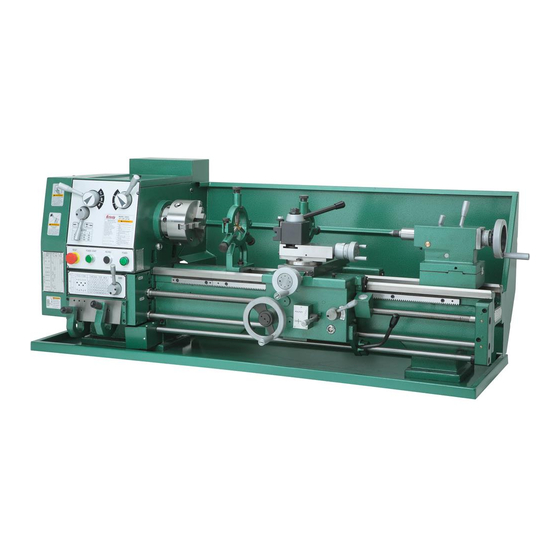
(Model g4003 shown)
Copyright © JANUAry, 2000 By grizzly iNdUstriAl, iNC., revised JUNe, 2013 (Bl)
WARNiNG: NO pORTiON Of THiS MANuAL MAy bE REpRODucED iN ANy SHApE
OR fORM WiTHOuT THE WRiTTEN AppROvAL Of GRizzLy iNDuSTRiAL, iNc.
#0350 priNted iN ChiNA
Advertisement
Table of Contents

Subscribe to Our Youtube Channel
Related Manuals for Grizzly G4002


Summary of Contents for Grizzly G4002
- Page 1 (For models manufactured since 8/12) (Model g4003 shown) Copyright © JANUAry, 2000 By grizzly iNdUstriAl, iNC., revised JUNe, 2013 (Bl) WARNiNG: NO pORTiON Of THiS MANuAL MAy bE REpRODucED iN ANy SHApE OR fORM WiTHOuT THE WRiTTEN AppROvAL Of GRizzLy iNDuSTRiAL, iNc.
- Page 2 This manual provides critical safety instructions on the proper setup, operation, maintenance, and service of this machine/tool. Save this document, refer to it often, and use it to instruct other operators. Failure to read, understand and follow the instructions in this manual may result in fire or serious personal injury—including amputation, electrocution, or death.
-
Page 3: Table Of Contents
Table of contents iNTRODucTiON ..........2 SEcTiON 5: ADJuSTMENTS ......32 Machine description ........2 gibs .............. 32 Contact info............ 2 steady/Follow rest ........33 Manual Accuracy ........... 2 tailstock ............34 g4002 Machine data sheet ......3 SEcTiON 6: MAiNTENANcE ......36 g4003 Machine data sheet ...... -
Page 4: Introduction
Before contacting, please get the serial number and manufacture date of your machine. This will help us help you faster. Grizzly Technical Support 1203 Lycoming Mall Circle Manufacture date Muncy, PA 17756 Phone: (570) 546-9663 Email: techsupport@grizzly.com... -
Page 5: G4002 Machine Data Sheet
MACHINE DATA SHEET Customer Service #: (570) 546-9663 · To Order Call: (800) 523-4777 · Fax #: (800) 438-5901 MODEL G4002 12" X 24" GEAR-HEAD, CAM LOCK SPINDLE, GAP BED LATHE Product Dimensions: Weight................................913 lbs. Width (side-to-side) x Depth (front-to-back) x Height................53 x 26 x 23 in. Footprint (Length x Width).......................... - Page 6 Paint................................. Epoxy Fluid Capacities Headstock Capacity..........................3.5 qt. Headstock Fluid Type..............ISO 32 (eg. Grizzly T23963, Mobil DTE Light) Gearbox Capacity........................... 1 – 2 Pumps Gearbox Fluid Type............. ISO 68 (SB1365, Grizzly T23962, Mobil Vactra 2) Apron Capacity............................0.5 qt.
- Page 7 Other Specifications: Country Of Origin ............................... China Warranty ................................1 Year Approximate Assembly & Setup Time ......................1 Hour Serial Number Location ................... ID Label on Middle of Headstock ISO 9001 Factory ..............................No CSA Certified ................................No Features: Carriage Mounted On/Off Control Lever Easy To Use Lever Controls Full Length Splash Guard Hardened and Ground Cast Iron Bed...
-
Page 8: G4003 Machine Data Sheet
MACHINE DATA SHEET Customer Service #: (570) 546-9663 · To Order Call: (800) 523-4777 · Fax #: (800) 438-5901 MODEL G4003 12" X 36" GEAR-HEAD, CAM LOCK SPINDLE, GAP BED LATHE Product Dimensions: Weight................................917 lbs. Width (side-to-side) x Depth (front-to-back) x Height................61 x 23 x 23. in. Footprint (Length x Width).......................... - Page 9 Paint................................. Epoxy Fluid Capacities Headstock Capacity..........................3.5 qt. Headstock Fluid Type..............ISO 32 (eg. Grizzly T23963, Mobil DTE Light) Gearbox Capacity........................... 1 – 2 Pumps Gearbox Fluid Type............. ISO 68 (SB1365, Grizzly T23962, Mobil Vactra 2) Apron Capacity............................0.5 qt.
- Page 10 Other Specifications: Country Of Origin ............................... China Warranty ................................1 Year Approximate Assembly & Setup Time ......................1 Hour Serial Number Location ..........................ID Label ISO 9001 Factory ..............................No CSA Certified ................................No Features: Carriage Mounted On/Off Control Lever Easy To Use Lever Controls Full Length Splash Guard Hardened and Ground Cast Iron Bed...
-
Page 11: Section 1: Safety
SEcTiON 1: SAfETy for your Own Safety, Read instruction Manual before Operating This Machine The purpose of safety symbols is to attract your attention to possible hazardous conditions. This manual uses a series of symbols and signal words intended to convey the level of impor- tance of the safety messages. - Page 12 WEARiNG pROpER AppAREL. do not wear fORciNG MAcHiNERy. do not force machine. clothing, apparel or jewelry that can become it will do the job safer and better at the rate for entangled in moving parts. Always tie back or which it was designed. cover long hair.
-
Page 13: Additional Safety For Metal Lathes
Additional Safety for Metal Lathes SpEED RATES. operating the lathe at the wrong cLEARiNG cHipS. Metal chips can easily cut speed can cause nearby parts to break or the bare skin—even through a piece of cloth. Avoid workpiece to come loose, which will result in dan- clearing chips by hand or with a rag. -
Page 14: Additional Chuck Safety
Additional chuck Safety ENTANGLEMENT. entanglement with a rotat- cHucK cApAciTy. Avoid exceeding the capacity ing chuck can lead to death, amputation, broken of the chuck by clamping an oversized workpiece. bones, or other serious injury. Never attempt to if the workpiece is too large to safely clamp with slow or stop the lathe chuck by hand, and always the chuck, use a faceplate or a larger chuck if pos- roll up long sleeves, tie back long hair, and remove... -
Page 15: Section 2: Power Supply
SEcTiON 2: pOWER SuppLy Availability circuit Requirements for 220v Before installing the machine, consider the avail- This machine is prewired to operate on a 220V ability and proximity of the required power supply power supply circuit that has a verified ground and circuit. -
Page 16: Grounding Instructions
Grounding instructions This machine MUST be grounded. In the event of certain malfunctions or breakdowns, grounding Serious injury could occur if you connect reduces the risk of electric shock by providing a the machine to power before completing the path of least resistance for electric current. setup process. -
Page 17: Power Connection
2 Amp Transformer Fuse Tianshui 98NO 97NO 95NC 96NC JBK5-63VATH power connection connecting power 1. Turn the machine power switch OFF. 2. Insert the power cord plug into a matching Before the machine can be connected to the power supply receptacle. The machine is power source, an electrical circuit, power cord, now connected to the power source. -
Page 18: Unpacking
unpacking piece inventory Your machine was carefully packaged for safe The following is a list of items shipped with your transportation. Remove the packaging materials machine. Before beginning setup, lay these items from around your machine and inspect it. If you out and inventory them. -
Page 19: Cleanup
cleanup Gasoline or products with low flash points can The unpainted surfaces of your machine are explode or cause fire if coated with a heavy-duty rust preventative that used to clean machin- prevents corrosion during shipment and storage. ery. Avoid cleaning with This rust preventative works extremely well, but it these products. -
Page 20: Site Considerations
Site considerations Weight Load Physical Environment Refer to the Machine Data Sheet for the weight The physical environment where the machine is of your machine. Make sure that the surface upon operated is important for safe operation and lon- which the machine is placed will bear the weight gevity of machine components. -
Page 21: Section 3: Assembly & Setup
An accessory stand is available 4-jaw chuck and a face plate. from grizzly. please see our current catalog for pricing. there are 2 holes in the base at the the 3-jaw chuck is a scroll-type chuck, meaning... - Page 22 To remove a chuck: turn the other cams in the same way. Make sure to support the chuck with one hand as place a piece of plywood across the lathe you align the last cam. the chuck may come bed and position it just under the chuck. the off at this point so it is important you are board should be at least 8"...
-
Page 23: Live Center
Live center Steady Rest the live center is used to support stock which the steady rest supports long, small diameter is too long to be supported by the chuck alone. stock that otherwise could not be turned. the stock protruding more than three times its diam- steady rest can also replace the tailstock to allow eter should be supported by the live center. -
Page 24: Follow Rest
follow Rest Mount the back plate on the spindle. Accurately measure the inside of the back relief bore on the 4-jaw chuck. this dimen- sion is critical, ± .001''. the follow rest is normally used with small diame- ter stock to prevent the workpiece from “springing” Face the back plate to true it. -
Page 25: Section 4: Controls
SEcTiON 4: cONTROLS Spindle Speeds Never change speeds while spindle or motor is in motion. the speed of the spindle is controlled by the posi- tions of the speed control knobs. see figure 12. By positioning the knobs using the chart in Figure 8, you can achieve all of these speed ranges: 70, 200, 220, 270, 360, 600, 800, 1000 and 1400 rpM. -
Page 26: Feed Direction
feed Direction Selecting the feed Never move selection levers while machine is running. the feed rod can be selected by rotating the handle to the left as in figure 15. Use this posi- the g4002/3 Metal lathe can cut left or right while tion for all feeding operations. -
Page 27: Feed Rate Chart
figure 16. Feed rate selector levers. important: do not force any selection lever on the machine. if the lever will not engage, rotate the chuck by hand while keeping light pressure on the selector. figure . Feed rate selection. As the chuck rotates, it aligns the gears and the selector will engage. -
Page 28: Thread Selection
Thread Selection While other thread pitches may be achieved, the g4002/3 comes with a chart that requires no gear changes for cutting inch threads. to achieve a desired thread pitch in inches, it is inch thread selection: necessary to determine the quick-change lever positions. - Page 29 these rest in a housing that pivots so that the gear can be engaged or disengaged. An Allen® head cap screw is located on the side of the hous- The threading dial cannot be used when ing. loosen this screw to change the positioning cutting metric threads.
- Page 30 Metric thread selection: to the left of the desired pitch is a small col- umn with a letter. this letter indicates place- the chart in figure 23 lists 29 metric threads that ment of the left hand quick change lever. Move the lever to the corresponding loca- can be cut on the g4002/3.
-
Page 31: Carriage Controls
carriage controls Metric threading requires 5 gear changes to achieve all of the available pitches listed on the chart. refer to figure 25 while reading the instructions below. the carriage handwheel allows the cutting tool to move along the length of the lathe bed. the cross To change gears: slide allows the cutting tool to travel perpendicu- lar to the bed. -
Page 32: Tool Post & Holder
More styles of tool holders are available through grizzly industrial, inc. Consult the latest catalog for styles, prices and ordering information. figure 27. spindle rotation control lever. -
Page 33: Tailstock Controls
Tailstock controls Test Run the tailstock serves many functions. the primary Now that the lathe is securely in place and you’ve use is for holding centers and drill chucks. the read the safety guidelines, it’s time to give the barrel has a Morse taper #3 bore and is imprinted machine a test run. -
Page 34: Section 5: Adjustments
SEcTiON 5: ADJuSTMENTS Gibs there are three main gib adjustments for the Model g4002/3. they are: the cross-slide gib, the compound slide gib and the saddle gib. cross-slide Gib - the gib on the cross-slide is adjusted by the two screws located at each end. -
Page 35: Steady/Follow Rest
Steady/follow Rest Saddle Gib - the saddle is supplied with a square head bolt on the front right hand side of the slide. Before making adjustments to the saddle gib, ensure that this bolt is loose by turning it counter To adjust the Steady Rest: clockwise. -
Page 36: Tailstock
Tailstock the tailstock on the Model g4002/3 is aligned at the factory with the headstock. it is recommended that you take the time to ensure that the tailstock is aligned to your own desired tolerances. To align the tailstock: Center drill a 6'' long piece of bar stock on both ends. - Page 37 — if the stock is thinner at the tailstock end, the tailstock needs to be moved away from the operator by at least the amount of the Lock down the tailstock after each adjust- taper. see figure 38. ment. viewed from above. Adjustment lock screw screw...
-
Page 38: Section 6: Maintenance
(or iso 32 equiv.) Apron ....grizzly t23962 (or iso 68 equiv.) Ball oilers ..grizzly t23963 (or iso 32 equiv.) oil ports ..grizzly t23963 (or iso 32 equiv.) leadscrew ..grizzly t23962 (or iso 68 equiv.) Bed Ways .. -
Page 39: Bearing Preload
45. Apron: Use grizzly t23962 or an iso 68 equiva- lent. the drain plug is located underneath the apron. the fill plug is located on top of the apron. -
Page 40: Section 7: Closure
Warranty/return information rent catalog for complete information regarding for your Model g4002/3. grizzly's warranty and return policy. if you need additional technical information relating to this if you need parts or help in assembling your machine, or if you need general assistance or... -
Page 41: Section 8: Wiring
Technical source. Support at (570) 546-9663. The photos and diagrams included in this section are best viewed in color. You can view these pages in color at www.grizzly.com. -39- Model G4002/G4003 (Mfg. Since 8/12) -
Page 42: Electrical Cabinet Wiring Diagram
Electrical cabinet Wiring Diagram 2 Amp Transformer Fuse Tianshui 98NO 97NO 95NC 96NC JBK5-63VATH 21NC 21NC 13NO 23NO 33NO 43NO Contactor Contactor Contactor Tianshui Tianshui Tianshui GSC1-1801 110V GSC1-1801 110V JZC3-40D 110V 22NC 22NC 14NO 24NO 34NO 44NO U2 Z1 Z2 Ground Z1 Z2 PE PE... -
Page 43: Motor & Control Panel Wiring Diagram
Motor & control panel Wiring Diagram Capacitor Ground 20MFD 450VAC 220V Motor Electrical Cabinet Start Capacitor 150MFD 250VAC Spindle Switch 6-15 Plug (As Recommended) Ground Electrical Cabinet Electrical Cabinet Electrical Cabinet Control Panel Stop Button Jog Button Power Lamp Power Button READ ELECTRICAL SAFETY -41- Model G4002/G4003 (Mfg. -
Page 44: Section 9: Parts
SEcTiON 9: pARTS Electrical REF PART # DESCRIPTION REF PART # DESCRIPTION P4002001 START BUTTON P4002052 CONTACTOR GSC1CJX4-D 110V P4002002 INDICATOR LIGHT P4002053 CONTACTOR JZC3-40D 110V P4002003 JOG BUTTON P4002054 FUSE HOLDER P4002004 RESET BUTTON 55V2 P4002055A CONTROL PANEL PLATE V2.03.07 P4002050 THERMAL PROT. -
Page 45: Headstock
Headstock -43- Model G4002/G4003 (Mfg. Since 8/12) -
Page 46: Headstock Parts List
Headstock parts List PART # DESCRIPTION PART # DESCRIPTION PCAP06M CAP SCREW M6-1 X 25 P4002154 WASHER P4002102 COVER P4002155 GEAR 40T P4002103 OIL SEAL P4002156 KEY CS X 8 P4002104 SPINDLE 16" P4002157 OIL SEAL 25 X 40 X 10 V1.10.96 P7212 BEARING D-7212 PR09M... - Page 47 REF PART # DESCRIPTION REF PART # DESCRIPTION 1106 P40021106 OIL SEAL 9.5 X 2.65 1112 P40021112 GEAR 1107 PCAP13M CAP SCREW M8-1.25 X 30 1113 PCAP68M CAP SCREW M6-1 X 8 1108 PB15M HEX BOLT M8-1.25 X 40 1114 PCAP68M CAP SCREW M6-1 X 8 1109 P40021109 HANDLE...
-
Page 48: Change Gear Train
change Gear Train REF PART # DESCRIPTION REF PART # DESCRIPTION PCAP26M CAP SCREW M6-1 X 12 P6202ZZ BALL BEARING 6202 ZZ P4002202 WASHER P4002209 SPACER P4002203 GEAR P4002210 QUADRANT PK12M KEY 5 X 5 X 30 P4002211 SHAFT PCAP26M CAP SCREW M6-1 X 12 P4002212 GEAR 40T... -
Page 49: Quick Change Gearbox
Quick change Gearbox -47- Model G4002/G4003 (Mfg. Since 8/12) -
Page 50: Quick Change Gearbox Parts List
Quick change Gearbox parts List REF PART # DESCRIPTION REF PART # DESCRIPTION P4003301 LEADSCREW P4002337 GEAR 16T PRP10M ROLL PIN 5 X 36 P4002342 COMBO GEAR 3PC SET P8103 THRUST BEARING 8103 P4002344 GEAR 16T P4002305 SHAFT P4002345 GEAR 18T PK19M KEY 5 X 5 X 14 P4002346... -
Page 51: Apron
Apron -49- Model G4002/G4003 (Mfg. Since 8/12) -
Page 52: Apron Parts List
Apron parts List PART # DESCRIPTION REF PART # DESCRIPTION 401V2 P4002401V2 HANDLE V2.08.12 P4002437 SAFETY SHIFTER 402V2 P4002402V2 HANDWHEEL V2.08.12 P4002438 CAP SCREW M8-1.25 X 6 403V2 P4002403V2 GRADUATED DIAL V2.08.12 P4002439 COMPRESSION SPRING 1 X 4.5 X 6 404V2 PSS03M SET SCREW M6-1 X 8 PSTB003M... -
Page 53: Saddle
Saddle -51- Model G4002/G4003 (Mfg. Since 8/12) -
Page 54: Saddle Parts List
Saddle parts List REF PART # DESCRIPTION REF PART # DESCRIPTION P4002501 SADDLE P4002522 SLIDE PLATE PS59M PHLP HD SCR M3-.5 X 14 P4002523 SLIDE PLATE P4002503 WIPER 524V2 P4002524V2 SLIDE PLATE 3 HOLES V2.01.09 PS24 PHLP HD SCR 8-32 X 3/8 PB19M HEX BOLT M8-1.25 X 24 P4002505... -
Page 55: Compound Rest
compound Rest REF PART # DESCRIPTION REF PART # DESCRIPTION P4002601 SCREW P8101 THRUST BEARING 8101 P4002602 P4002614 INDEX RING P4002603 COMPOUND SLIDE 615A P4002615A SPANNER NUT PN03M HEX NUT M8-1.25 616A P4002616A BRACKET P4002605 COMPOUND REST MOUNTING BOLT 617A P4002617A SHORT HANDLE P4002606 COMPOUND REST MOUNTING BOLT... -
Page 56: Tailstock
Tailstock -54- Model G4002/G4003 (Mfg. Since 8/12) -
Page 57: Tailstock Parts List
Tailstock parts List REF PART # DESCRIPTION REF PART # DESCRIPTION P4002701 CENTER PN09M HEX NUT M12-1.75 P4002702 KEY 8 X 30 P4002716 HANDLE P4002703 QUILL P4002717 LOCK SCREW P4002704 TAIL STOCK P4002718 LOCK SHAFT P4002705 BASE P4002719 HANDLE PCAP143M CAP SCREW M10-1.5 X 50 P4002720 SHAFT... -
Page 58: Motor Assembly
Motor Assembly REF PART # DESCRIPTION REF PART # DESCRIPTION P4002801 COVER P4002815 P4002802 SCREW P4002816 PULLEY P4002803 P4002817 MOTOR MOUNT BRACKET P4002812 MOTOR 2 HP 1.1KW V2.12.97 PW06M FLAT WASHER 12MM PW04M FLAT WASHER 10MM PB01M HEX BOLT M10-1.5 X 30 PB01M HEX BOLT M10-1.5 X 30 -56-... -
Page 59: Feed Rod Leadscrew
feed Rod Leadscrew REF PART # DESCRIPTION REF PART # DESCRIPTION P4002901 BRACKET P4002911 HANDLE PCAP25M CAP SCREW M6-1 X 11 P4002912 BRACKET P4002903 OIL CAP 6MM PCAP27M CAP SCREW M6-1 X 14 PRP34M ROLL PIN 6 X 55 PRP49M ROLL PIN 5 X 25 PSS02M SET SCREW M6-1 X 6... -
Page 60: Bed
REF PART # DESCRIPTION REF PART # DESCRIPTION 1001 P40031001 LATHE BED 1005 PCAP92M CAP SCREW M12-1.75 X 40 1002 P40031002 RACK 1008 P40031008 CHIP PAN 19" X 61" 1002B P40021002B RACK 6-1/8" SHORT 1009 PW06M FLAT WASHER 12MM 1003 PRP06M ROLL PIN 5 X 24 1010 PN09M HEX NUT M12-1.75... -
Page 61: Warranty Card
Would you recommend Grizzly Industrial to a friend? _____ Yes _____No Would you allow us to use your name as a reference for Grizzly customers in your area? Note: We never use names more than 3 times. _____ Yes _____No 10. - Page 62 FOLD ALONG DOTTED LINE Place Stamp Here GRIZZLY INDUSTRIAL, INC. P.O. BOX 2069 BELLINGHAM, WA 98227-2069 FOLD ALONG DOTTED LINE Send a Grizzly Catalog to a friend: Name_______________________________ Street_______________________________ City______________State______Zip______ TAPE ALONG EDGES--PLEASE DO NOT STAPLE...
-
Page 63: Warranty & Returns
WARRANTy & RETuRNS Grizzly Industrial, Inc. warrants every product it sells for a period of 1 year to the original purchaser from the date of purchase. This warranty does not apply to defects due directly or indirectly to misuse, abuse, negligence, accidents, repairs or alterations or lack of maintenance.
Need help?
Do you have a question about the G4002 and is the answer not in the manual?
Questions and answers