Table of Contents
Advertisement
Quick Links
Advertisement
Table of Contents

Related Manuals for Grizzly G0517g


Summary of Contents for Grizzly G0517g
- Page 1 MODEL G0517 MILL/DRILL INSTRUCTION MANUAL COPYRIGHT © MAY, 2006 BY GRIZZLY INDUSTRIAL, INC. WARNING: NO PORTION OF THIS MANUAL MAY BE REPRODUCED IN ANY SHAPE OR FORM WITHOUT THE WRITTEN APPROVAL OF GRIZZLY INDUSTRIAL, INC. #TR8234 PRINTED IN CHINA.
- Page 2 ���� ������ �������� �������� ������ ������������ �� ��� ������ ������ ���������� ����������� ��� ������� �� ���� ������������������ ������� �� ����� ���������� ��� ������ ��� ������������ ����� �� ���� ������ ��� ������ �� ������� �������� ������� ��������� ����������� ������������� �� ������ ���...
-
Page 3: Table Of Contents
SECTION 4: OPERATIONS ... 15 Head/Quill Travel ... 15 Table Travel ... 15 Installing/Removing Morse Taper Sleeves ... 16 Installing/Removing Drawbar Tooling ... 17 Installing Drill Chuck ... 18 Changing Speeds ... 18 Drilling ... 19 Drilling Speeds ... 20 Milling Speed ... 21 SECTION 5: ACCESSORIES ... -
Page 4: Introduction
INTRODUCTION Foreword We are proud to offer the Model G0517 Mill/Drill. This machine is part of a growing Grizzly family of fine woodworking and metalworking machinery. When used according to the guidelines set forth in this manual, you can expect years of trouble-free, enjoyable operation and proof of Grizzly’s com-... -
Page 5: Machine Data Sheet
Machine Data Sheet Customer Service #: (570) 546-9663 · To Order Call: (800) 523-4777 · Fax #: (800) 438-5901 MODEL G0517 MILL/DRILL W/ STAND Product Dimensions: Weight... 331 lbs. Length/Width/Height...29-1/2 x 27-1/8 x 77-5/8 in. Foot Print (Length/Width)... 17-3/4 x 14-1/2 in. - Page 6 The information contained herein is deemed accurate as of 5/12/2006 and represents our most recent product specifications. Model G0517 Due to our ongoing improvement efforts, this information may not accurately describe items previously purchased. PAGE 2 OF 3 Model G0517 Mill/Drill...
-
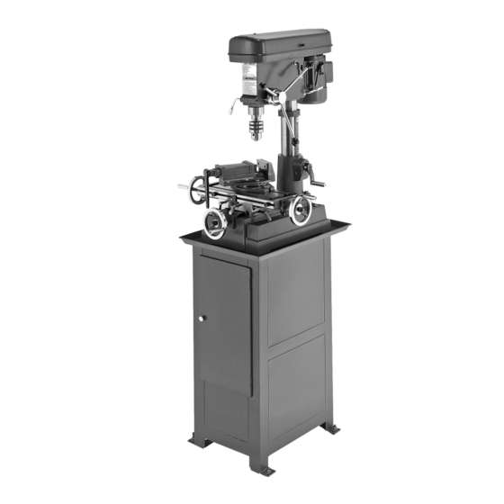
Page 7: Identification
Model G0517 Mill/Drill Identification A. ON/OFF Switch w/Safety Key B. Belt Tension Handle C. Belt Tension Locks D. Headstock Clamp Handle E. Head Elevation Crank (Z Axis, Major) Column Lock G. Longitudinal Handwheels (X Axis) H. Splash Tray Cross Feed Handwheel (Y Axis) Cabinet Stand K. -
Page 8: Section 1: Safety
Wear protective hair covering to con- tain long hair and wear non-slip footwear. 6. NEVER OPERATE MACHINERY WHEN TIRED, OR UNDER THE INFLUENCE OF OPERATING DRUGS OR ALCOHOL. Be mentally alert at all times when running machinery. OPERATING MACHINERY. Model G0517 Mill/Drill... - Page 9 Follow instructions for lubricating and changing accessories. 16. MAKE SURE GUARDS ARE IN PLACE AND WORK CORRECTLY BEFORE USING MACHINERY. Model G0517 Mill/Drill 17. REMOVE WRENCHES. Make a habit of checking for keys and adjusting wrenches before turn- ing machinery ON.
-
Page 10: Additional Safety For Mill/Drills
OPERATION. Never start the machine with the cutting tool pressed against the workpiece. Feed the cutting tool evenly into the workpiece. Back the drill bit out of deep holes to clear chips when drilling. 10. AVOIDING ENTANGLEMENT. -
Page 11: Section 2: Circuit Requirements
110V Circuit ... 15 Amps Plug/Receptacle Type Included Plug Type ... NEMA 5-15 Figure 1. Typical 5-15 plug and receptacle. Model G0517 Mill/Drill Electrocution or fire could result if this machine is not grounded correctly or if your electrical configu- ration does not comply with local and state codes. -
Page 12: Section 3: Set Up
K. MT #2/#3 & MT#1/#2 Sleeves ... 1 Each Wrenches and Drift Key ... 1 Each M. Mounting Bolts, Washers, Nuts ... 4 Each N. Drill Chuck & Key ... 1 Each Figure 2. Main parts inventory. Figure 3. Component inventory. -
Page 13: Clean Up
Remove this protective coating with a sol- vent cleaner or citrus-based degreaser such as Grizzly’s G7895 Degreaser. Some parts may need to be removed before they can be thoroughly cleaned. For optimum performance from your machine, make sure you clean all moving parts or slid- ing contact surfaces that are coated. -
Page 14: Assembly
Machine mounts, shown in Figure 5, give the advantage of fast leveling and vibration reduction. For the Model G0517, we recommend using four Grizzly Model G7159 machine mounts. Figure 5. Machine mount example. Bolting the machine to the floor is the strongest option, but also the most permanent. - Page 15 With the help of an assistant, place the mill/ drill headstock onto the column, as shown in Figure 10. Figure 10. Headstock installed on base column. Center the headstock over the table and tighten the lock handle shown in Figure 11.
-
Page 16: Test Run
Figure 14. Using the belt tension lever to tighten/loosen the belts. Clear all tools and other components away from the mill/drill, and ensure that the belt cover is closed. Make sure you are familiar with the machine safety and controls. -
Page 17: Section 4: Operations
OMMEND that you read books, trade maga- zines, or get formal training before begin- ning any projects. Regardless of the con- tent in this section, Grizzly Industrial will not be held liable for accidents caused by lack of training. Head/Quill Travel... -
Page 18: Installing/Removing Morse Taper Sleeves
Insert the drift key into the quill slot as shown in Figure 22. Drift Key Figure 22. Drift key inserted in quill slot. Hold the sleeve with one hand and gently tap the drift key with a hammer to knock the sleeve out. Model G0517 Mill/Drill... -
Page 19: Installing/Removing Drawbar Tooling
Installing/Removing Drawbar Tooling The Model G0517 includes an M12-1.75 drawbar. Use the drawbar to connect the included drill chuck arbor or an aftermarket end mill holder. See Page 23 for recommended end mill holders. Always DISCONNECT MACHINE FROM POWER when installing or removing tooling. -
Page 20: Installing Drill Chuck
Installing Drill Chuck The drill chuck fits on the arbor with a taper fit. To install the drill chuck: UNPLUG THE MILL/DRILL! Prepare the mating surfaces on the arbor taper and the chuck by cleaning them thor- oughly. Retract the chuck jaws all the way inside of the chuck. -
Page 21: Drilling
CLEARING CHIPS: Raise the drill bit often to clear chips and cool the drill bit. This will ease the work of the mill/drill motor and extend the life of your drill bits. -
Page 22: Drilling Speeds
The chart shown in Figure 31 is intended as a guide only. Always follow the manufacturer's speed recommendations if provided with your drill bits, cutters, or hole saws. Exceeding the recommended speeds by large amounts may be dangerous to the operator. -
Page 23: Milling Speed
Figure 32. Cutting speed table for HSS cutting tools. Measure the diameter of your cutting tool in inches. Model G0517 Mill/Drill Use the formula in Figure 33 to determine the needed speed for your operation: Figure 33. Speed formula for milling. -
Page 24: Section 5: Accessories
G8865: ⁄ " - ⁄ "; G8866: ⁄ "- ⁄ ". Figure 35. Model G8865 13-PC Alloy Drill Bits. -22- H5685—4" Rotary Table ⁄ " x ⁄ ", ⁄ " The perfect rotary table for all you model makers ⁄... - Page 25 G2863—MT#3 Arbor for Face Mill This 2 ⁄ " Face Mill accepts four carbide inserts. The Model G2863 must be purchased with this face mill for use on this mill/drill. Figure 40. G2861 Face mill. Model G0517 Mill/Drill G5608—MT#3, G5609—MT#3, ",...
-
Page 26: Section 6: Maintenance
Keep tables rust-free with regular applications of products like G96 Gun Treatment or Boeshield ® T-9. See below for Grizzly model numbers: G2871—Boeshield T-9 12 oz Spray ® G2870—Boeshield T-9 4 oz Spray ®... -
Page 27: Adjusting Gibs
Figure 46. Handwheel oil fittings. Figure 47. Oil fittings on left-side of table. Figure 48. Oil fittings on right-side of table. Model G0517 Mill/Drill Adjusting Gibs The gibs control play in the longitudinal and cross feed table movement; they are pre-adjusted at the factory and typically need no adjustments until the machine is well used. -
Page 28: Section 7: Service
SECTION 7: SERVICE This section is provided for your convenience—it is not a substitute for the Grizzly Service Department. If you need help troubleshooting, you need replacement parts, or you are unsure of how to perform the pro- cedures in this section, then feel free to call our Technical Support at (570) 546-9663. - Page 29 1. Clean shaft and lubricate with a light coat of oil. 2. Fully release the quill lock. 3. Increase the feed shaft return spring tension. 1. Replace the bearings. 2. Replace the quill shaft. 1. Remove drill bit and reinstall. -27-...
-
Page 30: Electrical Components
�� �� �� �� Wiring Diagram �������� ����� ����� ����� ��� ����� �� ����� �� ����� �� ������ �� ����� �� ����� �� �� ��������� ������� ������� �� �� �� �� �� �� ������ �� �� �� Model G0517 Mill/Drill... -
Page 31: Stand/Base Parts Breakdown
�� � �� �� �� �� �� � �� �� �� �� �� �� �� �� �� �� � Model G0517 Mill/Drill �� �� �� �� �� �� � � �� �� �� � � � �� �� �� ��... -
Page 32: Stand/Base Parts List
MUST maintain the original location and readability of the labels on the machine. If any label is removed or becomes unreadable, REPLACE that label before using the machine again. Contact Grizzly at (800) 523-4777 or www.grizzly.com to order new labels. -30-... -
Page 33: Headstock Parts Breakdown
��� ��� �� �� �� �� �� �� �� ��� ��� ��� ��� ��� ��� ��� ��� ��� ��� Model G0517 Mill/Drill ��� ��� ��� ��� ��� ��� ��� �� ��� �� ��� �� �� �� �� ��� �� ��... -
Page 34: Headstock Parts List
MUST maintain the original location and readability of the labels on the machine. If any label is removed or becomes unreadable, REPLACE that label before using the machine again. Contact Grizzly at (800) 523-4777 or www.grizzly.com to order new labels. -32-... -
Page 35: Warranty And Returns
WARRANTY AND RETURNS Grizzly Industrial, Inc. warrants every product it sells for a period of 1 year to the original purchaser from the date of purchase. This warranty does not apply to defects due directly or indirectly to misuse, abuse, negligence, accidents, repairs or alterations or lack of maintenance. -
Page 37: Warranty Card
Do you think your machine represents a good value? Would you recommend Grizzly Industrial to a friend? Would you allow us to use your name as a reference for Grizzly customers in your area? Note: We never use names more than 3 times. - Page 38 FOLD ALONG DOTTED LINE FOLD ALONG DOTTED LINE Send a Grizzly Catalog to a friend: GRIZZLY INDUSTRIAL, INC. P.O. BOX 2069 BELLINGHAM, WA 98227-2069 Name_______________________________ Street_______________________________ City______________State______Zip______ TAPE ALONG EDGES--PLEASE DO NOT STAPLE Place Stamp Here...
- Page 40 Buy Direct and Save with Grizzly Visit Our Website Today And Discover Why • SECURE ORDERING • ORDERS SHIPPED WITHIN 24 HOURS • E-MAIL RESPONSE WITHIN ONE HOUR Trusted, Proven and a Great Value! ®: Grizzly Is The Industry Leader! ®...
Need help?
Do you have a question about the G0517g and is the answer not in the manual?
Questions and answers