Table of Contents
Advertisement
Quick Links
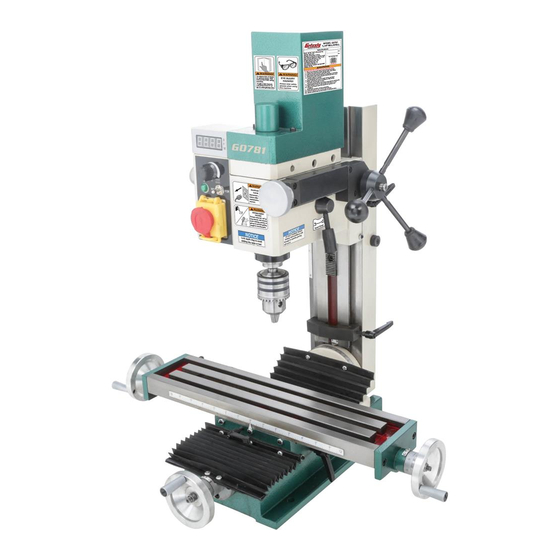
MODEL G0781
4" X 18"
⁄
HP MILL/DRILL
3
4
OWNER'S MANUAL
(For models manufactured since 02/15)
COPYRIGHT © AUGUST, 2015 BY GRIZZLY INDUSTRIAL, INC., REVISED OCTOBER, 2015 (JH)
WARNING: NO PORTION OF THIS MANUAL MAY BE REPRODUCED IN ANY SHAPE
OR FORM WITHOUT THE WRITTEN APPROVAL OF GRIZZLY INDUSTRIAL, INC.
#JH17413 PRINTED IN CHINA
V1.10.15
Advertisement
Table of Contents

Related Manuals for Grizzly G0781


Summary of Contents for Grizzly G0781
- Page 1 OWNER'S MANUAL (For models manufactured since 02/15) COPYRIGHT © AUGUST, 2015 BY GRIZZLY INDUSTRIAL, INC., REVISED OCTOBER, 2015 (JH) WARNING: NO PORTION OF THIS MANUAL MAY BE REPRODUCED IN ANY SHAPE OR FORM WITHOUT THE WRITTEN APPROVAL OF GRIZZLY INDUSTRIAL, INC.
- Page 2 This manual provides critical safety instructions on the proper setup, operation, maintenance, and service of this machine/tool. Save this document, refer to it often, and use it to instruct other operators. Failure to read, understand and follow the instructions in this manual may result in fire or serious personal injury—including amputation, electrocution, or death.
-
Page 3: Table Of Contents
Table of Contents INTRODUCTION ..........2 SECTION 5: ACCESSORIES ......26 Contact Info............ 2 SECTION 6: MAINTENANCE ......29 Manual Accuracy ........... 2 Schedule ............29 Identification ........... 3 Cleaning and Protecting ......29 Controls & Components ......... 4 Lubrication ........... 29 Machine Data Sheet ........ -
Page 4: Introduction
ID label (see below). This information is required for us to provide proper tech support, and it helps us determine if updated documenta- tion is available for your machine. Manufacture Date Serial Number Model G0781 (Mfd. Since 2/15) -
Page 5: Identification
Spindle Power Light X-Axis Handwheel Chuck X-Axis Lock Lever Way Cover Y-Axis Handwheel Coarse Downfeed Motor Handle Headstock Lock Lever Spindle Direction Switch Speed Range Lever Limit Block Work Column Tilt Nut Table Y-Axis Lock Lever Model G0781 (Mfd. Since 2/15) -
Page 6: Controls & Components
Figure 2. G0781 controls (left side). H. Headstock Depth Gauge: Indicates upward and downward travel of headstock along col- umn for consistent drilling depth. -
Page 7: Machine Data Sheet
MACHINE DATA SHEET Customer Service #: (570) 546-9663 · To Order Call: (800) 523-4777 · Fax #: (800) 438-5901 MODEL G0781 4" X 18" 3/4 HP MILL/DRILL Product Dimensions: Weight................................137 lbs. Width (side-to-side) x Depth (front-to-back) x Height............... 26-1/2 x 20-1/2 x 31 in. - Page 8 The information contained herein is deemed accurate as of 4/15/2019 and represents our most recent product specifications. Model G0781 PAGE 2 OF 2 Due to our ongoing improvement efforts, this information may not accurately describe items previously purchased. Model G0781 (Mfd. Since 2/15)
-
Page 9: Section 1: Safety
Never operate under the influence of drugs or injury or blindness from flying particles. Everyday alcohol, when tired, or when distracted. eyeglasses are NOT approved safety glasses. Model G0781 (Mfd. Since 2/15) - Page 10 Make sure they are properly installed, you experience difficulties performing the intend- undamaged, and working correctly BEFORE ed operation, stop using the machine! Contact our operating machine. Technical Support at (570) 546-9663. Model G0781 (Mfd. Since 2/15)
-
Page 11: Additional Safety For Mills/Drills
Use this machine with respect and caution to lessen the possibility of operator injury. If normal safety precautions are over- looked or ignored, serious personal injury may occur. Model G0781 (Mfd. Since 2/15) -
Page 12: Section 2: Power Supply
-10- Model G0781 (Mfd. Since 2/15) - Page 13 Two-prong outlets do not meet the grounding requirements for this machine. Do not modify or use an adapter on the plug provided—if it will not fit the outlet, have a qualified electrician install the proper outlet with a verified ground. -11- Model G0781 (Mfd. Since 2/15)
-
Page 14: Section 3: Setup
Keep hair, clothing, and you are completely satisfied with the machine and jewelry away from mov- have resolved any issues between Grizzly or the ing parts at all times. shipping agent. You MUST have the original pack- Entanglement can result aging to file a freight claim. -
Page 15: Inventory
Handwheel Handles w/Screws ....3 fully check around/inside the machine and packaging materials. Often, these items get lost in packaging materials while unpack- ing or they are pre-installed at the factory. Figure 4. Inventory included with machine. -13- Model G0781 (Mfd. Since 2/15) -
Page 16: Cleanup
Figure 5. T23692 Orange Power Degreaser. Repeat Steps 2–3 as necessary until clean, then coat all unpainted surfaces with a quality metal protectant to prevent rust. -14- Model G0781 (Mfd. Since 2/15) -
Page 17: Site Considerations
Only install in an Shadows, glare, or strobe effects that may distract access restricted location. or impede the operator must be eliminated. Minimum 30" For Maintenance " " " Figure 6. G0781 working clearances. -15- Model G0781 (Mfd. Since 2/15) -
Page 18: Lifting & Placing
Lag Screw Flat Washer Figure 7. Example of recommended lifting sling Machine Base position. Workbench Secure machine to workbench, following instructions in Bench Mounting. Figure 9. "Direct Mount" setup. -16- Model G0781 (Mfd. Since 2/15) -
Page 19: Assembly
Assembly Test Run Except for the handwheel handles, the G0781 Once assembly is complete, test run the machine mill/drill was fully assembled at the factory. to ensure it is properly connected to power and safety components are functioning correctly. Use a standard screwdriver to attach handwheel handles, as shown in Figure 10. -
Page 20: Spindle Break-In
This safety feature must work properly before proceeding with regular operations. Call Tech Support for help. Congratulations! The test run is complete. Continue to Spindle Break-In. -18- Model G0781 (Mfd. Since 2/15) -
Page 21: Inspections & Adjustments
Shift speed range lever in "HIGH" position, and run spindle at 1000 RPM for 5 minutes in each direction of rotation. Repeat Step 6 at 1800 RPM. 8. Turn mill/drill OFF. Congratulations! The Spindle Break-In is complete. -19- Model G0781 (Mfd. Since 2/15) -
Page 22: Section 4: Operations
11. Disconnects machine from power. formal training before beginning any proj- ects. Regardless of the content in this sec- tion, Grizzly Industrial will not be held liable for accidents caused by lack of training. -20- Model G0781 (Mfd. Since 2/15) -
Page 23: Spindle Speed
Also, there are a large number of easy-to-use spindle speed calculators that can be found on the internet. These sources will help you take into account all applicable variables to determine the best spindle speed for the operation. -21- Model G0781 (Mfd. Since 2/15) -
Page 24: Using Spindle
0.001" increments, with one ment, rotate fine downfeed handwheel clock- full revolution equaling 0.060" of spindle travel. wise 0.010", then tighten headstock lock lever. Turn mill/drill ON and perform cutting pass. -22- Model G0781 (Mfd. Since 2/15) -
Page 25: Adjusting
Lever Headstock Column Tilt Figure 15. Location of headstock lock lever and Figure 16. Headstock tilt controls. coarse downfeed handwheel. Use coarse downfeed handwheel to adjust headstock height. Tighten lock lever to secure setting. -23- Model G0781 (Mfd. Since 2/15) -
Page 26: Moving Table
Figure 18. Location of graduated dials. The table handwheels have graduated dials in 0.001" increments, with one full revolution equal- ling 0.0625". These dials provide an easy way to gauge precise table movements while milling. -24- Model G0781 (Mfd. Since 2/15) -
Page 27: Installing/Removing Tooling
Tooling Secure spindle with spindle pin and tighten drawbar, as shown in Figure 21. The Model G0781 includes a 3–16mm drill chuck Note: overtighten drawbar. with an R-8 arbor (see Figure 19). The R-8 arbor... -
Page 28: Section 5: Accessories
⁄ "-16 studs. Racks To reduce this risk, only install accessories can be bolted to the wall or side of machine for recommended for this machine by Grizzly. easy access. NOTICE Refer to our website or latest catalog for additional recommended accessories. - Page 29 G5646—10-Pc. Precision Angle Block Set T23964—Moly-D Multi-Purpose NLGI#2 Speed set-up, production and inspection with Grease the Grizzly Precision Angle Block Set and Thin Parallel Set made from hardened and precision- ground steel. Each set offers a wide range of sizes for any job.
- Page 30 ⁄ " T-slots, two locking screws, and pre- within 0.0003". cision base. ⁄ " mounting slots. T24799 T24800 Figure 33. G5758 Tilt Table. Figure 31. T24799 and T24800 Precision Parallel Blocks. -28- Model G0781 (Mfd. Since 2/15)
-
Page 31: Section 6: Maintenance
Remove any rust build-up from unpainted cast iron surfaces of mill/drill and treat with a non- staining lubricant after cleaning. Protect other unpainted cast iron surfaces with regular applica- tions of ISO 68 oil. -29- Model G0781 (Mfd. Since 2/15) - Page 32 Figure 35. Location of cross-slide ways. Use mineral spirits and a brush to clean X-axis leadscrew. Allow leadscrew to dry. Apply thin coat of ISO 68 machine oil to exposed X-axis leadscrew threads. -30- Model G0781 (Mfd. Since 2/15)
-
Page 33: Section 7: Service
1. Adjust placement, change mounting area, shim, or vibration or noisy workbench or floor. tighten mounting hardware. operation. 2. Motor or machine component loose. 2. Inspect/replace damaged bolts/nuts, and retighten with thread locking fluid. -31- Model G0781 (Mfd. Since 2/15) - Page 34 1. Mill/drill operated at maximum speed for 1. Allow mill/drill to cool; avoid operating at maximum overheats. extended period. speed for long times. 2. Fan cover clogged. 2. Clean motor, let cool, and reduce workload. -32- Model G0781 (Mfd. Since 2/15)
-
Page 35: Adjusting Gibs
Y-Axis Set X-Axis Set Screws Screws and (2 of 3) Hex Nuts Figure 38. Location of gib adjustment set screws. -33- Model G0781 (Mfd. Since 2/15) -
Page 36: Head Counterbalance Spring
Figure 41. Removing and replacing fuse. Insert new fuse and re-install fuse holder Head Counterbalance underneath headstock. Spring Figure 40. Location of head counterbalance spring. -34- Model G0781 (Mfd. Since 2/15) -
Page 37: Replacing Brushes
Repeat Steps 3–5 for second brush assem- bly on other side of motor. Replace motor cover. Note: Run mill/drill at a medium spindle speed setting for a minimum of five minutes before performing any workpiece operations. -35- Model G0781 (Mfd. Since 2/15) -
Page 38: Tramming Spindle
Figure 46. Dial test indicator mounted. Tools Needed Dial Test Indicator (with at least 0.0005" resolution) ....1 Indicator Holder (mounted on the quill/spindle) ....1 Precision Parallel Block (at least 9" in length) ........1 -36- Model G0781 (Mfd. Since 2/15) - Page 39 6–7 until you are satisfied with the spindle so the head does not move loosely while you axis alignment along the table X-axis. adjust it. Remember to tighten all the tilt lock bolts after adjusting the head. -37- Model G0781 (Mfd. Since 2/15)
-
Page 40: Section 8: Wiring
Technical Support at (570) 546-9663. The photos and diagrams included in this section are best viewed in color. You can view these pages in color at www.grizzly.com. -38- Model G0781 (Mfd. Since 2/15) -
Page 41: Wiring Overview
Rear Circuit Board Panel Potentiometer FWD/REV Switch Power Light KEDU KJD12 Switch Fuse Holder Front Panel Bottom Inside Panel Power Side Cord Panel Figure 49. G0781 wiring overview. READ ELECTRICAL SAFETY -39- Model G0781 (Mfd. Since 2/15) ON PAGE 38! -
Page 42: Wiring Diagram
Front Panel (Viewed From Backside) Rear Panel Side Panel Bottom Inside Panel (Viewed From Backside) (Viewed From Backside) To Plug FUSE 8AL250V 110 VAC Neutral 5-15 Plug (Pre-Wired) Ground READ ELECTRICAL SAFETY -40- Model G0781 (Mfd. Since 2/15) ON PAGE 38! -
Page 43: Section 9: Parts
SECTION 9: PARTS We do our best to stock replacement parts when possible, but we cannot guarantee that all parts shown are available for purchase. Call (800) 523-4777 or visit www.grizzly.com/parts to check for availability. Headstock 176 177 176 177... - Page 44 Please Note: We do our best to stock replacement parts whenever possible, but we cannot guarantee that all parts shown here are available for purchase. Call (800) 523-4777 or visit our online parts store at www.grizzly.com to check for availability.
-
Page 45: Column
P0781219 RETURN SPRING COVER P0781239 PHLP HD SCR M4-.7 X 6 P0781220 BUSHING P0781240 KEY 4 X 4 X 8 P0781221 FLAT HD SCR M5-.8 X 10 P0781241 ADJUSTABLE HANDLE 45L, M6-1 X 25 -43- Model G0781 (Mfd. Since 2/15) -
Page 46: Table
ADJUSTABLE HANDLE 45L, M6-1 X 25 P0781316 Y-AXIS BEARING HOUSING P0781336 HEX NUT M6-1 P0781317 DIAL INDICATOR P0781337 SET SCREW M6-1 X 25 P0781318 THRUST BEARING 51200 P0781338 SCALE INDICATOR P0781319 COOLANT HOSE CONNECTOR M10-1.5 X 10 -44- Model G0781 (Mfd. Since 2/15) -
Page 47: Accessories
T-SLOT NUT 1/2" X M8-1.25 P0781407 FUSE 8A 250V 0.25" FAST-ACTING GLASS P0781416 STUD-UDE M8-1.25 X 45, 11, 25 P0781408 SPANNER WRENCH 38–42MM P0781417 DRILL CHUCK B-16 1-13MM P0781409 WRENCH 13 X 16MM OPEN ENDS -45- Model G0781 (Mfd. Since 2/15) -
Page 48: Labels & Cosmetics
Safety labels help reduce the risk of serious injury caused by machine hazards. If any label comes off or becomes unreadable, the owner of this machine MUST replace it in the original location before resuming operations. For replacements, contact (800) 523-4777 or www.grizzly.com. -46-... - Page 49 Would you recommend Grizzly Industrial to a friend? _____ Yes _____No Would you allow us to use your name as a reference for Grizzly customers in your area? Note: We never use names more than 3 times. _____ Yes _____No 10.
- Page 50 FOLD ALONG DOTTED LINE Place Stamp Here GRIZZLY INDUSTRIAL, INC. P.O. BOX 2069 BELLINGHAM, WA 98227-2069 FOLD ALONG DOTTED LINE Send a Grizzly Catalog to a friend: Name_______________________________ Street_______________________________ City______________State______Zip______ TAPE ALONG EDGES--PLEASE DO NOT STAPLE...
-
Page 51: Warranty & Returns
WARRANTY & RETURNS Grizzly Industrial, Inc. warrants every product it sells for a period of 1 year to the original purchaser from the date of purchase. This warranty does not apply to defects due directly or indirectly to misuse, abuse, negligence, accidents, repairs or alterations or lack of maintenance.
Need help?
Do you have a question about the G0781 and is the answer not in the manual?
Questions and answers