Table of Contents
Advertisement
Quick Links
MODEL G0982/G0983
6" X 27" MILL/DRILL
w/MIRROR DISPLAY
OWNER'S MANUAL
(For models manufactured since 01/24)
COPYRIGHT © JUNE, 2024 BY GRIZZLY INDUSTRIAL, INC.
WARNING: NO PORTION OF THIS MANUAL MAY BE REPRODUCED IN ANY SHAPE
OR FORM WITHOUT THE WRITTEN APPROVAL OF GRIZZLY INDUSTRIAL, INC.
#CS23156 PRINTED IN CHINA
V1.06.24
***Keep for Future Reference***
Advertisement
Table of Contents

Related Manuals for Grizzly G0982


Summary of Contents for Grizzly G0982
- Page 1 (For models manufactured since 01/24) COPYRIGHT © JUNE, 2024 BY GRIZZLY INDUSTRIAL, INC. WARNING: NO PORTION OF THIS MANUAL MAY BE REPRODUCED IN ANY SHAPE OR FORM WITHOUT THE WRITTEN APPROVAL OF GRIZZLY INDUSTRIAL, INC. #CS23156 PRINTED IN CHINA V1.06.24...
- Page 2 This manual provides critical safety instructions on the proper setup, operation, maintenance, and service of this machine/tool. Save this document, refer to it often, and use it to instruct other operators. Failure to read, understand and follow the instructions in this manual may result in fire or serious personal injury—including amputation, electrocution, or death.
-
Page 3: Table Of Contents
G0982 Control Panel ........54 G0982 Column ..........55 SECTION 2: POWER SUPPLY ...... 15 G0982 Spindle Motor & Speed Sensor ..56 G0982 Chip Guard Safety Switch ....56 SECTION 3: SETUP ........17 G0983 Main Wiring Overview ...... 57 Needed for Setup ......... -
Page 4: Introduction
Always consider safety first, as it applies to your individual working conditions. Use this and other machinery with caution and respect. Failure to do so could result in serious personal injury, damage to equip- ment, or poor work results. Model G0982/G0983 (Mfd. Since 01/24) -
Page 5: G0982 Identification
E. Downfeed Selector Handle M. Chuck Coarse Downfeed Handle N. X-Axis Handwheel G. Table O. X-Axis Lock Handle H. Y-Axis Lock Handle Column To reduce your risk of serious injury, read this entire manual BEFORE using machine. Model G0982/G0983 (Mfd. Since 01/24) -
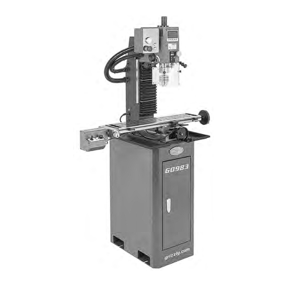
Page 6: G0983 Identification
H. X-Axis Handwheel S. Leadscrew Selector Knob Y-Axis Lock Handle X-Axis Power Feed & Controls X-Axis Lock Handle U. Column K. Table To reduce your risk of serious injury, read this entire manual BEFORE using machine. Model G0982/G0983 (Mfd. Since 01/24) -
Page 7: Controls & Components
Illuminates when spindle rotates counterclockwise, as viewed from above. N. Spindle Depth DRO: Displays spindle travel Spindle rotation does not need to be stopped and depth. before rotation is reversed. E. Start/Stop Button: Starts and stops spindle rotation. Model G0982/G0983 (Mfd. Since 01/24) - Page 8 AA. Y-Axis Handwheel: Moves table along : Press to toggle between absolute or rela- X-axis (front and back) and has a graduated tive measurement for selected axis. dial measured in 0.001" increments. One full revolution of handwheel equals 0.10". Model G0982/G0983 (Mfd. Since 01/24)
- Page 9 AJ. X-Axis Travel Limit Stop (1 of 2): Adjust for operation to limit power feed table movement on X-axis. Figure 7. Chip guard components (G0982 AK. Leadscrew Selector Knob: Rotate to shown). engage or release power feed drive gear.
-
Page 10: Machine Data Sheet (G0982)
MACHINE DATA SHEET Customer Service #: (570) 546-9663 · To Order Call: (800) 523-4777 · Fax #: (800) 438-5901 MODEL G0982 6" X 27" MILL/DRILL WITH MIRROR DISPLAY Product Dimensions: Weight................................324 lbs. Width (side-to-side) x Depth (front-to-back) x Height............34-1/2 x 24-1/2 x 65-1/2 in. - Page 11 The information contained herein is deemed accurate as of 6/10/2024 and represents our most recent product specifications. Model G0982 PAGE 2 OF 3 Due to our ongoing improvement efforts, this information may not accurately describe items previously purchased. Model G0982/G0983 (Mfd. Since 01/24)
-
Page 12: Machine Data Sheet (G0983)
The information contained herein is deemed accurate as of 6/10/2024 and represents our most recent product specifications. Model G0983 PAGE 1 OF 3 Due to our ongoing improvement efforts, this information may not accurately describe items previously purchased. -10- Model G0982/G0983 (Mfd. Since 01/24) - Page 13 The information contained herein is deemed accurate as of 6/10/2024 and represents our most recent product specifications. Model G0983 PAGE 2 OF 3 Due to our ongoing improvement efforts, this information may not accurately describe items previously purchased. -11- Model G0982/G0983 (Mfd. Since 01/24)
-
Page 14: Section 1: Safety
Never operate under the influence of drugs or injury or blindness from flying particles. Everyday alcohol, when tired, or when distracted. eyeglasses are NOT approved safety glasses. -12- Model G0982/G0983 (Mfd. Since 01/24) - Page 15 EXPERIENCING DIFFICULTIES. If at any time debris. Make sure they are properly installed, you experience difficulties performing the intend- undamaged, and working correctly BEFORE ed operation, stop using the machine! Contact our operating machine. Technical Support at (570) 546-9663. -13- Model G0982/G0983 (Mfd. Since 01/24)
-
Page 16: Additional Safety For Mill/Drills
OFF position and press Emergency Stop button use. This will prevent them from being thrown by to avoid a possible sudden startup once power is the spindle upon startup. restored. -14- Model G0982/G0983 (Mfd. Since 01/24) -
Page 17: Section 2: Power Supply
-15- Model G0982/G0983 (Mfd. Since 01/24) - Page 18 Model G0983 power feed unit. Do not modify or use an adapter on the plug provided—if it will not fit the outlet, have a qualified electrician install the proper outlet with a verified ground. -16- Model G0982/G0983 (Mfd. Since 01/24)
-
Page 19: Section 3: Setup
IMPORTANT: Save all packaging materials until you are completely satisfied with the machine and have resolved any issues between Grizzly or the shipping agent. You MUST have the original pack- aging to file a freight claim. It is also extremely helpful if you need to return your machine later. -
Page 20: Inventory
Inventory Crate (Figure 11) X-Axis Handwheel Handle (G0982 Only) ... 1 Power Cord for Mill/Drill 16AWG 72" ..1 K. Power Adapter Power Cord 18AWG 55" The following is a list of items shipped with your (G0983 Only) ..........1 machine. -
Page 21: Hardware Recognition Chart
Hardware Recognition Chart USE THIS CHART TO MATCH UP HARDWARE DURING THE INVENTORY AND ASSEMBLY PROCESS. Flat Head Screw -19- Model G0982/G0983 (Mfd. Since 01/24) -
Page 22: Cleanup
Figure 12. T23692 Orange Power Degreaser. Repeat Steps 2–3 as necessary until clean, then coat all unpainted surfaces with a quality metal protectant to prevent rust. -20- Model G0982/G0983 (Mfd. Since 01/24) -
Page 23: Site Considerations
Shadows, glare, or strobe effects that may distract access restricted location. or impede the operator must be eliminated. Electrical Wall Connection " = Min. 30 26½" 64" 55" G0982 G0983 Figure 13. Minimum working clearances. -21- Model G0982/G0983 (Mfd. Since 01/24) -
Page 24: Assembly
Figure 14. Chip tray attached to stand. and use a forklift (or other lifting equipment) rated for Fully tighten X-axis, Y-axis, and Z-axis lock weight of this machine. handles (see Figures 5–6 on Pages 5–6). -22- Model G0982/G0983 (Mfd. Since 01/24) -
Page 25: Anchoring To Floor
How you anchor these fasteners to the floor will depend on the type of shop floor you have. See Figure 17 for Figure 16. Machine attached to stand (G0982 an example of how to mount the stand to a con- shown). -
Page 26: Power Connection
Figure 18. Location of Emergency Stop button (G0982 shown). Connect 16AWG mill/drill power cord to male receptacle on column (see Figure 19). Male Receptacle 16AWG Mill/Drill Power Cord Figure 19. Power cord connected to mill/drill. -24- Model G0982/G0983 (Mfd. Since 01/24) -
Page 27: Test Run
4) the spindle and power Emergency feed controls work correctly. Stop Button Figure 21. Spindle control panel (G0982 shown). Twist Emergency Stop button clockwise until Serious injury or death can result from it springs out (see Figure 22). This resets using this machine BEFORE understanding switch so spindle can start. - Page 28 16. Press Reverse button and Start/Stop button to reset them. 12. Slowly turn spindle speed dial clockwise to test variable-speed for counterclockwise — G0982: Test Run is complete! Complete direction, then turn it all the way counter- Spindle Break-In on Page 28 before clockwise.
- Page 29 X-Axis (1 of 2) Lock Handle 26. Turn speed control dial all the way counter- clockwise and move direction switch to neu- Figure 26. Right X-axis table controls. tral position to correct fault mode. -27- Model G0982/G0983 (Mfd. Since 01/24)
-
Page 30: Spindle Break-In
Test Run is complete! Button Complete Spindle Break-In before proceed- ing with operations. Figure 27. Spindle control panel (G0982 shown). Spindle Break-In Allow spindle to run clockwise (as viewed from above) at about 100 RPM for 10 minutes. -
Page 31: Section 4: Operations
Read books/magazines or get formal training before beginning any proj- ects. Regardless of the content in this sec- tion, Grizzly Industrial will not be held liable for accidents caused by lack of training. Keep hair, clothing, and jewelry away from mov- ing parts at all times. -
Page 32: Using Spindle Downfeed
Turn spindle depth DRO ON and zero it out. Use coarse downfeed handles to raise and lower spindle while referencing spindle depth DRO for precise movement. Figure 29. Left spindle downfeed components (G0982 shown). -30- Model G0982/G0983 (Mfd. Since 01/24) - Page 33 Figure 31. Spindle depth DRO. headstock. Press OFF/ON button when operation is Tighten downfeed selector handle (see complete to conserve battery. Figure 30) to engage fine downfeed knob. Loosen quill lock with quill lock lever. -31- Model G0982/G0983 (Mfd. Since 01/24)
-
Page 34: Controlling Table Travel
Always stay Figure 33. Location of manual table controls clear of handle when using (G0982 shown). power feed. Failure to do so could lead to entangle- ment or impact injuries. -32- Model G0982/G0983 (Mfd. Since 01/24) - Page 35 "0" posi- Connect power feed to provided 5A power tion and moving direction switch to neutral supply and grounded 5-15 outlet. Power light (middle) position. will illuminate. -33- Model G0982/G0983 (Mfd. Since 01/24)
-
Page 36: Adjusting Headstock
Z-Axis Handwheel Figure 38. Tapping drill chuck/arbor on block of wood. Attempt to separate drill chuck and arbor by hand —if they separate, repeat Steps 3–4. Figure 37. Location of Z-axis handwheel (G0982 shown). -34- Model G0982/G0983 (Mfd. Since 01/24) -
Page 37: Removing/Installing Tooling
Removing Tooling DISCONNECT MACHINE FROM POWER! DO NOT completely unscrew drawbar before striking it with hammer in following step. Unscrew drawbar cap to remove (see You will damage threads on drawbar and Figure 40). arbor. -35- Model G0982/G0983 (Mfd. Since 01/24) -
Page 38: Determining Spindle Speed
Use drawbar lock lever or 8mm hex wrench in best spindle speed for the operation. top of drawbar and spindle spanner wrench in holes in bottom of spindle to tighten drawbar (see Figure 41 on Page 35). Install drawbar cap. -36- Model G0982/G0983 (Mfd. Since 01/24) -
Page 39: Section 5: Accessories
⁄ "-20 drawbar. serious personal injury or machine damage. To reduce this risk, only install accessories recommended for this machine by Grizzly. NOTICE Refer to our website or latest catalog for additional recommended accessories. T25615—Milling for Home Machinists... -
Page 40: Section 6: Maintenance
Keep unpainted cast-iron surfaces rust-free and fix the problem before continuing operations: with regular applications a quality metal protectant (see Figure 47 for offerings from Grizzly). • Loose mounting bolts. •... -
Page 41: Lubrication
Wipe ways with recommended lubrication, then move components back and forth several times over full range of travel to spread lubricant Figure 50. Location of X-axis ways (G0982 and ensure smooth movement. shown). -39-... - Page 42 Items Needed Stiff Brushes ............2 Mineral Spirits ........As Needed SB1365 or ISO 68 Equivalent .... As Needed Phillips Head Screwdriver #2 ......1 X-Axis Leadscrew Figure 54. Location of X-axis leadscrew (G0982 shown). -40- Model G0982/G0983 (Mfd. Since 01/24)
-
Page 43: Checking/Replacing Belt
Note: Re-apply oil that may have been Headstock removed during the cleaning process to quill Cover surface around rack (refer to Quill Surface lubrication section on Page 40). Figure 56. Location of headstock cover and securing screws. -41- Model G0982/G0983 (Mfd. Since 01/24) - Page 44 Step 6. Figure 57. Location of belt and pulleys. Install spindle speed sensor if it was removed. Install headstock cover. Approximately " Deflection Motor Spindle Pulley Pulley Figure 58. Correct belt deflection. -42- Model G0982/G0983 (Mfd. Since 01/24)
-
Page 45: Section 7: Service
2. Wiring broken, disconnected, or corroded. 2. Fix broken wires or disconnected/corroded work/display is connections (Page 52). incorrect. 3. Speed sensor at fault. 3. Replace sensor. 4. Spindle speed DRO circuit board at fault. 4. Inspect/replace if at fault. -43- Model G0982/G0983 (Mfd. Since 01/24) - Page 46 5. Replace/sharpen bit; index bit to workpiece; reduce feed rate (Page 30). 6. Spindle extended too far down during or at 6. Fully retract spindle and lower headstock (Page 34). beginning of operation. This increases rigidity. -44- Model G0982/G0983 (Mfd. Since 01/24)
- Page 47 9. Wiring broken, disconnected, or corroded. 9. Fix broken wires or disconnected/corroded connections (Page 52). 10. Motor brushes worn out. 10. Replace brushes (Page 50). 11. Direction switch at fault. 11. Replace switch. -45- Model G0982/G0983 (Mfd. Since 01/24)
- Page 48 1. Replace dial. speed will not 2. Wiring broken, disconnected, or corroded. 2. Fix broken wires or disconnected/corroded adjust or is connections (Page 52). inconsistent. 3. Power feed potentiometer at fault. 3. Test/replace if at fault. -46- Model G0982/G0983 (Mfd. Since 01/24)
-
Page 49: Replacing Fuse
Mill/Drill Power Cord Battery Cover Figure 60. Mill/drill power cord connected to male receptacle on column (G0982 shown). Pry fuse compartment (see Figure 61) from male receptacle on column. Figure 62. Example of removing spindle depth DRO battery cover. Remove old battery, dispose of it according to state and federal regulations, then replace it with a new one. -
Page 50: Adjusting Gibs
Z-axis way cover in place (see Figure 65). X-Axis Y-Axis Gib Screw Gib Screw (Right) (Front) Figure 63. Location of front/right gib screws (G0982 shown). Figure 65. Location of Z-axis cover Phillips head screws. -48- Model G0982/G0983 (Mfd. Since 01/24) -
Page 51: Adjusting Leadscrew Backlash
Gib Screw (Bottom) Tool Needed Hex Wrench 3mm (Long) ........1 Figure 66. Location of Z-axis gib screws (G0982 shown). The X-axis leadscrew nut is accessed from under the left side of the table and has cap screws at Use Z-axis handwheel to move headstock the top (see Figure 67). -
Page 52: Replacing Motor Brushes
Remove (2) flat head cap screws shown in Assembly Figure 68. Remove cap screw shown in Figure 68, then remove headstock cover. Headstock Figure 70. Location of spindle motor brush caps. Cover Figure 68. Location of headstock cover and securing screws. -50- Model G0982/G0983 (Mfd. Since 01/24) - Page 53 To replace power feed motor brushes: Replace both power feed motor brushes and DISCONNECT MACHINE FROM POWER! install brush caps. Install power feed motor (if removed). Install power feed side and bottom covers. -51- Model G0982/G0983 (Mfd. Since 01/24)
-
Page 54: Section 8: Wiring
Technical Support at (570) 546-9663. The photos and diagrams included in this section are best viewed in color. You can view these pages in color at www.grizzly.com. -52- Model G0982/G0983 (Mfd. Since 01/24) -
Page 55: G0982 Main Wiring Overview
Spindle Depth DRO (Battery Operated) Column Power Connection Column Electrical Compartment (Page 55) Chip Guard Safety Switch (Page 56) Control Panel (Page 54) Column Neutral 110 VAC 5-15 Plug Ground READ ELECTRICAL SAFETY -53- Model G0982/G0983 (Mfd. Since 01/24) ON PAGE 52! -
Page 56: G0982 Control Panel
To Column Button (Page 55) WENZHOU J16-E-271B USB Port To Spindle Start/Stop Button Motor Emergency Stop Button WENZHOU J19-271B (Page 56) KEDU HY57B Figure 74. Control box wiring. READ ELECTRICAL SAFETY -54- Model G0982/G0983 (Mfd. Since 01/24) ON PAGE 52! -
Page 57: G0982 Column
DC1 DC2 AC3 AC4 8 P1 P2 P3 Circuit Board WGPCB FC750BJ-2/110V 15A 250V Fuse Ground Power Connection Socket Plug IEC C14 PST-101 Figure 76. Lower column wiring. READ ELECTRICAL SAFETY -55- Model G0982/G0983 (Mfd. Since 01/24) ON PAGE 52! -
Page 58: G0982 Spindle Motor & Speed Sensor
G0982 Spindle Motor & Speed Sensor Speed Sensor RSD-1A(M8-28) Motor 110V Figure 77. Spindle speed sensor. To Control Box (Page 54) Figure 78. Spindle motor wiring. G0982 Chip Guard Safety Switch Chip Guard Safety Switch KEDU QKS7 To Column (Page 55) Figure 79. -
Page 59: G0983 Main Wiring Overview
Column Power Connection Column Electrical Compartment (Page 59) Chip Guard Safety Switch (Page 60) Z-Axis Sensor (Page 61) Control Panel (Page 58) Column Neutral 110 VAC 5-15 Plug Ground READ ELECTRICAL SAFETY -57- Model G0982/G0983 (Mfd. Since 01/24) ON PAGE 52! -
Page 60: G0983 Control Panel
To Column Button (Page 59) WENZHOU J16-E-271B USB Port To Spindle Start/Stop Button Motor Emergency Stop Button WENZHOU J19-271B (Page 60) KEDU HY57B Figure 80. Control box wiring. READ ELECTRICAL SAFETY -58- Model G0982/G0983 (Mfd. Since 01/24) ON PAGE 52! -
Page 61: G0983 Column
WGPCB FC750BJ-2/110V Socket Plug IEC C14 SPT-101 To 3-Axis (Page 61) 15A 250V Fuse Ground To Y-Axis Sensor (Page 61) To X-Axis Sensor Figure 82. Lower column wiring. READ ELECTRICAL SAFETY -59- Model G0982/G0983 (Mfd. Since 01/24) ON PAGE 52! -
Page 62: G0983 Spindle Motor & Speed Sensor
(Page 57) Figure 84. Spindle motor wiring. G0983 Chip Guard Safety Switch Chip Guard Safety Switch KEDU QKS7 To Column (Page 59) Figure 85. Chip guard safety switch. READ ELECTRICAL SAFETY -60- Model G0982/G0983 (Mfd. Since 01/24) ON PAGE 52! -
Page 63: G0983 3-Axis Dro & Sensors
Figure 87. X- and Y-axis sensors. Z-Axis Figure 86. 3-axis DRO and spindle depth DRO Sensor wiring. Figure 88. Z-axis sensor. -61- BUY PARTS ONLINE AT GRIZZLY.COM! Model G0982/G0983 (Mfd. Since 01/24) Scan QR code to visit our Parts Store. -
Page 64: G0983 Power Feed Wiring Overview
X-Axis Limit Switches (Page 63) X-Axis Power Feed (Page 63) X-Axis Power Feed Limit Switches Figure 90. X-axis limit switch wiring. Figure 89. Power feed box wiring (as viewed from bottom). READ ELECTRICAL SAFETY -62- Model G0982/G0983 (Mfd. Since 01/24) ON PAGE 52! -
Page 65: G0983 Power Feed
X-Axis Motor Power 3-Pin Socket ZHOUSHI GX12-3P Indicator HL-1 WH24-2 F4K7 Fault Indicator Direction Switch Potentiometer KEDU HY29K – – Circuit Board ZHENYI XMT-2403 Power Feed Box Bottom Cover READ ELECTRICAL SAFETY -63- Model G0982/G0983 (Mfd. Since 01/24) ON PAGE 52! -
Page 66: Section 9: Parts
SECTION 9: PARTS We do our best to stock replacement parts when possible, but we cannot guarantee that all parts shown are available for purchase. Call (800) 523-4777 or visit www.grizzly.com/parts to check for availability. Headstock 64 63 G0983 G0982 -64- BUY PARTS ONLINE AT GRIZZLY.COM! - Page 67 SPINDLE MOTOR MOUNTING PLATE P0982042 CAP SCREW M6-1 X 14 P0982087 CAP SCREW M10-1.5 X 50 P0982043 FLAT WASHER 6MM P0982088 FLAT WASHER 10MM -65- BUY PARTS ONLINE AT GRIZZLY.COM! Model G0982/G0983 (Mfd. Since 01/24) Scan QR code to visit our Parts Store.
-
Page 68: Column
FLAT WASHER 8MM P0982117 HANDLE SCREW M8-1.25 X 55 P0982135 CAP SCREW M8-1.25 X 30 P0982118 LOCK NUT M8-1.25 P0982136 LOCK WASHER 8MM -66- BUY PARTS ONLINE AT GRIZZLY.COM! Model G0982/G0983 (Mfd. Since 01/24) Scan QR code to visit our Parts Store. -
Page 69: Table
Table G0982 Only -67- BUY PARTS ONLINE AT GRIZZLY.COM! Model G0982/G0983 (Mfd. Since 01/24) Scan QR code to visit our Parts Store. - Page 70 LOCK NUT M8-1.25 P0982210 RIVET 2 X 4MM NAMEPLATE, STEEL P0982235 FLAT WASHER 8MM P0982211 DIAL INDICATOR P0982236 BALL OILER 6MM PRESS-IN (G0982) P0982212 HANDWHEEL 20 X M8-1 P0982237 TABLE COVER PLUG (G0982) P0982213 HEX NUT M8-1.25 THIN P0982238 COMPRESSION SPRING 1 X 14.2 X 33...
-
Page 71: Chip Guard & Way Covers
CHIP GUARD MOUNTING BRACKET P0982326 SPLASH GUARD (SMALL) P0982313 SET SCREW M4-.7 X 6 P0982327 MAGNET 6MM P0982314 PHLP HD SCR M4-.7 X 8 -69- BUY PARTS ONLINE AT GRIZZLY.COM! Model G0982/G0983 (Mfd. Since 01/24) Scan QR code to visit our Parts Store. -
Page 72: Stand & Accessories
P0982358 DRILL CHUCK JT6 1/8"-5/8" P0982368 WRENCH 14 X 17MM OPEN-ENDS P0982359 DRAWBAR/QUILL LOCK LEVER P0982369 WRENCH 17 X 19MM OPEN-ENDS -70- BUY PARTS ONLINE AT GRIZZLY.COM! Model G0982/G0983 (Mfd. Since 01/24) Scan QR code to visit our Parts Store. -
Page 73: Main Electrical Components
Main Electrical Components 420-1 420-2 G0982 Only G0983 Only G0983 Only G0983 Only -71- BUY PARTS ONLINE AT GRIZZLY.COM! Model G0982/G0983 (Mfd. Since 01/24) Scan QR code to visit our Parts Store. - Page 74 P0982449 FUSE 15A 250V P0982424 COLUMN COVER P0982450 POWER CORD 16G 3W 72" 5-15P P0982425 FLAT HD SCR M3-.5 X 12 -72- BUY PARTS ONLINE AT GRIZZLY.COM! Model G0982/G0983 (Mfd. Since 01/24) Scan QR code to visit our Parts Store.
-
Page 75: G0983 Power Feed & 3-Axis Sensors
G0983 Power Feed & 3-Axis Sensors 505 506 503-2 503-1 -73- BUY PARTS ONLINE AT GRIZZLY.COM! Model G0982/G0983 (Mfd. Since 01/24) Scan QR code to visit our Parts Store. - Page 76 PHLP HD SCR M3-.5 X 12 P0983610 COMPRESSION SPRING 0.7 X 4 X 25 P0983811 SPACER BLOCK P0983611 LEADSCREW SELECTOR KNOB M6-1 P0983812 Z-AXIS SENSOR BRACKET -74- BUY PARTS ONLINE AT GRIZZLY.COM! Model G0982/G0983 (Mfd. Since 01/24) Scan QR code to visit our Parts Store.
-
Page 77: G0982 Labels & Cosmetics
Safety labels help reduce the risk of serious injury caused by machine hazards. If any label comes off or becomes unreadable, the owner of this machine MUST replace it in the original location before resuming operations. For replacements, contact (800) 523-4777 or www.grizzly.com. -75- BUY PARTS ONLINE AT GRIZZLY.COM! -
Page 78: G0983 Labels & Cosmetics
Safety labels help reduce the risk of serious injury caused by machine hazards. If any label comes off or becomes unreadable, the owner of this machine MUST replace it in the original location before resuming operations. For replacements, contact (800) 523-4777 or www.grizzly.com. -76- BUY PARTS ONLINE AT GRIZZLY.COM! -
Page 79: Warranty & Returns
WARRANTY & RETURNS Grizzly Industrial, Inc. warrants every product it sells for a period of 1 year to the original purchaser from the date of purchase. This warranty does not apply to defects due directly or indirectly to misuse, abuse, negligence, accidents, repairs or alterations or lack of maintenance.
Need help?
Do you have a question about the G0982 and is the answer not in the manual?
Questions and answers
The drill is it AC current motor?