Table of Contents
Advertisement
Quick Links
Advertisement
Table of Contents

Related Manuals for Grizzly G0756


Summary of Contents for Grizzly G0756
- Page 1 OWNER'S MANUAL (For models manufactured since 03/13) Copyright © MAy, 2013 By grizzly industriAl, inC., WARNING: NO PORTION Of ThIS MANUAL MAy bE REPRODUcED IN ANy ShAPE OR fORM WIThOUT ThE WRITTEN APPROvAL Of GRIzzLy INDUSTRIAL, INc. #dM15670 printed in ChinA...
- Page 2 This manual provides critical safety instructions on the proper setup, operation, maintenance, and service of this machine/tool. Save this document, refer to it often, and use it to instruct other operators. Failure to read, understand and follow the instructions in this manual may result in fire or serious personal injury—including amputation, electrocution, or death.
-
Page 3: Table Of Contents
Table of contents INTRODUcTION ..........2 SEcTION 6: MAINTENANcE ......32 Machine description ........2 schedule ............32 Contact info............ 2 ongoing ............32 Manual Accuracy ........... 2 daily, After operations ........32 identification ........... 3 Annually ............32 Control panel ..........4 Cleaning and protecting ...... -
Page 4: Introduction
Machine Description Manual Accuracy We are proud to provide a high-quality owner’s We are proud to offer the Model g0756 18-speed manual with your new machine! heavy-duty drill press. When used according to the guidelines set forth in this manual, you can... -
Page 5: Identification
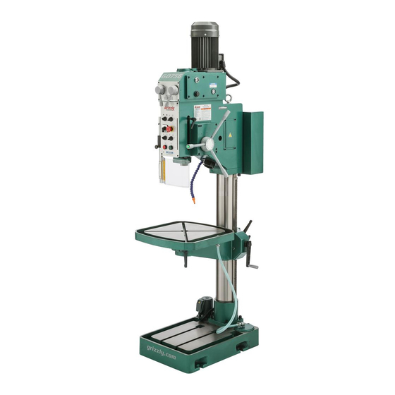
Coolant nozzle D. speed Control levers K. oil site glass E. Control panel (see Page 4 for details) Coarse downfeed handles M. table lock handles Chip guard G. Coolant pump N. table height Adjustment Crank Model G0756 (Mfg. Since 2/13) -
Page 6: Control Panel
E. Spindle Stop button: stops all work. Spindle Start button: starts machine when Master power switch has already been turned to the on position and the high/low spindle speed range switch is turned to 1 or Model G0756 (Mfg. Since 2/13) -
Page 7: Machine Data Sheet
MACHINE DATA SHEET Customer Service #: (570) 546-9663 · To Order Call: (800) 523-4777 · Fax #: (800) 438-5901 MODEL G0756 HEAVY-DUTY DRILLING MACHINE Product Dimensions: Weight................................1026 lbs. Width (side-to-side) x Depth (front-to-back) x Height..............22 x 37 x 89-1/2 in. - Page 8 The information contained herein is deemed accurate as of 6/4/2013 and represents our most recent product specifications. Model G0756 PAGE 2 OF 3 Due to our ongoing improvement efforts, this information may not accurately describe items previously purchased. Model G0756 (Mfg. Since 2/13)
-
Page 9: Section 1: Safety
Model G0756 (Mfg. Since 2/13) - Page 10 Contact our debris. Make sure they are properly installed, technical support at (570) 546-9663. undamaged, and working correctly. Model G0756 (Mfg. Since 2/13)
-
Page 11: Safety For Drill Presses
If normal safety precautions sonal injury, damage to equipment, or poor are overlooked or ignored, serious personal work results. injury may occur. Model G0756 (Mfg. Since 2/13) -
Page 12: Section 2: Power Supply
To reduce the risk of these hazards, avoid over- loading the machine during operation and make sure it is connected to a power supply circuit that meets the requirements in the following section. -10- Model G0756 (Mfg. Since 2/13) -
Page 13: Grounding Instructions
Minimum Gauge Size ......14 AWG of circuit, the reconnection must be made Maximum Length (Shorter is better)..50 ft. by a qualified electrician and comply with all local codes and ordinances. -11- Model G0756 (Mfg. Since 2/13) -
Page 14: Section 3: Setup
If you cannot find an item on this list, care- fully check around/inside the machine and packaging materials. Often, these items get lost in packaging materials while unpack- ing or they are pre-installed at the factory. -12- Model G0756 (Mfg. Since 2/13) -
Page 15: Cleanup
4. t23692 orange power degreaser. off the rest with the rag. repeat Steps 2–3 as necessary until clean, then coat all unpainted surfaces with a quality metal protectant to prevent rust. -13- Model G0756 (Mfg. Since 2/13) -
Page 16: Site Considerations
Only install in an Shadows, glare, or strobe effects that may distract access restricted location. or impede the operator must be eliminated. ⁄ " 22" 30" minimum for maintenance 30" figure 5. Minimum working clearances. -14- Model G0756 (Mfg. Since 2/13) -
Page 17: Lifting & Placing
With another person to help to steady the figure 7. popular method for anchoring machine, lift it just enough to clear the pallet machinery to a concrete floor. and any floor obstacles, then place it in its final position. -15- Model G0756 (Mfg. Since 2/13) -
Page 18: Arbor/Chuck Assembly
Damage caused by running the drill press onto a block of wood with moderate force without oil in the reservoir will not be cov- (see figure 8). ered under warranty. figure 8. installing arbor into chuck. -16- Model G0756 (Mfg. Since 2/13) -
Page 19: Power Connection
To connect the power cord to the machine: turn the master power switch to oFF, then open the electrical cabinet door located at the back of the machine. To Plug/Power Supply figure 10. ground and hot wires connected. -17- Model G0756 (Mfg. Since 2/13) -
Page 20: Test Run
1) the motor powers up and runs correctly, 2) the eMergenCy stop button and chip guard safety features work correctly, and 3) the motor rotates in the correct direction (machine is not wired out of phase). -18- Model G0756 (Mfg. Since 2/13) - Page 21 (as standing in front of the machine), it is turning in the correct direction. —if the bit turns from left to right (as standing in front of the machine), see Page 17 for instructions on correcting phase polarity. -19- Model G0756 (Mfg. Since 2/13)
-
Page 22: Coolant System
Coolant drain table trough to the oFF position. Running the pump without adequate cool- ant can significantly damage the pump, which will not be covered under warranty. figure 13. table trough and coolant drain. -20- Model G0756 (Mfg. Since 2/13) -
Page 23: Spindle Break-In
11. run the machine at 440 rpM for another 15 minutes to allow it cool down. Congratulations! spindle break-in is complete. We recommend changing the headstock and gearbox oil before operating the machine further (refer to lubrication on Page 33). -21- Model G0756 (Mfg. Since 2/13) -
Page 24: Section 4: Operations
Read books/magazines or get formal training before beginning any proj- ects. Regardless of the content in this sec- tion, Grizzly Industrial will not be held liable for accidents caused by lack of training. -22- Model G0756 (Mfg. Since 2/13) -
Page 25: Installing Tapered Tooling
An improperly installed arbor can become a projectile and result in serious injury to operator or others nearby. Always verify figure 18. using drift key to remove arbor. arbor is correctly installed before beginning drilling operations. -23- Model G0756 (Mfg. Since 2/13) -
Page 26: Depth Stop
(see figure 21). push the table to the desired location, and guide the rack on the side of the column. re-tighten the lock handles. figure 20. setting depth stop handle. -24- Model G0756 (Mfg. Since 2/13) -
Page 27: Selecting Spindle Rpm
Carbide Insert Type One-Piece Type 1800 Tenon/Plug Cutters Soft Wood Hard Wood Plastic Brass Aluminum Mild Steel 3/8" – 1/2" 1200 1000 5/8" – 1" figure 22. Cutting speed table for hss cutting tools. -25- Model G0756 (Mfg. Since 2/13) -
Page 28: Drilling Mode
"drilling" mode option with the toggle switch. refer to Selecting Spindle RPM on Page 25, and choose the closest available spindle rpM. turn the Master power switch ON. press the spindle start button and begin the drilling operation. -26- Model G0756 (Mfg. Since 2/13) -
Page 29: Automatic Power Downfeed
Master power switch ON, and press the spindle start button. pull the coarse downfeed handle down towards the front of the machine until the automatic downfeed begins. -27- Model G0756 (Mfg. Since 2/13) -
Page 30: Tapping Mode
10. Begin threading. Without disengaging the tap from the threads, frequently alternate spindle rotation by pressing any end button to reverse spindle and eject chips from the hole. Frequently removing chips will prevent galling and tap breakage. -28- Model G0756 (Mfg. Since 2/13) -
Page 31: Section 5: Accessories
Made for ⁄ " t-slots. To reduce this risk, only install accessories recommended for this machine by Grizzly. NOTICE Refer to our website or latest catalog for additional recommended accessories. G5753—Drill Press vise - 6"... - Page 32 Also includes a ⁄ " clamping set for the 4-slot table. everything you need in one great set! h7616 h7617 figure 32. high pressure oil cans. figure 30. rotary table with dividing plates. -30- Model G0756 (Mfg. Since 2/13)
- Page 33 Made in an iso 9001 certi- & #7, ⁄ "-18 & F, ⁄ "-16 & ⁄ " and ⁄ "-13 & ⁄ ". fied factory. figure 34. precision keyless drill chuck. figure 33. Commonly used tap and drill set. -31- Model G0756 (Mfg. Since 2/13)
-
Page 34: Section 6: Maintenance
Check quantity/quality of coolant (Page 20). • Keep unpainted cast iron surfaces rust-free with regular applications of iso 68 way oil (see Page Annually: 30 for offerings form grizzly). Change headstock oil (Page 33). • -32- Model G0756 (Mfg. Since 2/13) -
Page 35: Lubrication
Fill the headstock with oil to the red mark on figure 37. oil flow sight glass. the site glass (see figure 36). -33- Model G0756 (Mfg. Since 2/13) -
Page 36: Ball Oilers
39. headstock side ball oiler locations cap screws. -34- Model G0756 (Mfg. Since 2/13) -
Page 37: Section 7: Service
7. Motor fan is rubbing on fan cover. 7. replace dented fan cover or damaged fan. 8. Motor bearings are at fault. 8. test by rotating shaft; rotational grinding/loose shaft requires bearing replacement. -35- Model G0756 (Mfg. Since 2/13) -
Page 38: Drill Press Operations
3. spindle speed/feed rate is too fast. 3. set spindle speed correctly (Page 25) or use a slower feed rate. 4. spindle extended too far down. 4. Fully retract spindle and raise table. this increases rigidity. -36- Model G0756 (Mfg. Since 2/13) -
Page 39: Replacing Lamp Bulb
42. torque limiter and set screw. turn the set screw less than a quarter of a turn using a 4mm hex wrench. one small adjustment should compensate for any wear on the limiter disc. -37- Model G0756 (Mfg. Since 2/13) -
Page 40: Section 8: Wiring
Technical source. Support at (570) 546-9663. The photos and diagrams included in this section are best viewed in color. You can view these pages in color at www.grizzly.com. -38- Model G0756 (Mfg. Since 2/13) -
Page 41: Wiring Overview
Page 45 elevation limit switches electrical Page 43 panel Page 45 Chip guard limit switch power plug Page 43 Page 40 Work lamp Page 41 Coolant pump Page 41 READ ELECTRICAL SAFETY -39- Model G0756 (Mfg. Since 2/13) ON PAGE 38! -
Page 42: Power Connection Wiring
Power connection Wiring ground 220 vAc 3-Phase 15-15 Plug (as recommended) Electric clutch Wiring to electrical panel Page 45 ground Front View side view figure 43. electronic clutch wiring. READ ELECTRICAL SAFETY -40- Model G0756 (Mfg. Since 2/13) ON PAGE 38! -
Page 43: Motor & Pump Wiring
44. spindle motor wiring. Ground electrical panel Page 45 PUMP MOTOR figure 45. Coolant pump wiring. WORK LAMP Control panel Page 43 figure 46. Work lamp wiring. READ ELECTRICAL SAFETY -41- Model G0756 (Mfg. Since 2/13) ON PAGE 38! -
Page 44: Control Panel
C2SS2-10B-10 C2SS2-10B-10 Lower Elevation Limit DRILLING/TAPPING SWITCH SPINDLE DIRECTION Switch LX5W-A11N MCB-01 MLB-01 CP1-10R-01 Ground STOP BUTTON START BUTTON Chip Guard (Viewed from behind) Limit Switch Machine Frame READ ELECTRICAL SAFETY -42- Model G0756 (Mfg. Since 2/13) ON PAGE 38! -
Page 45: Control Panel & Limit Switches
Mode switch spindle direction switch start Button stop Button lower elevation limit switch figure 31. Control panel and limit switch locations (viewed from behind). READ ELECTRICAL SAFETY -43- Model G0756 (Mfg. Since 2/13) ON PAGE 38! -
Page 46: Electrical Panel Wiring
U2 V2 W2 10 12 10 11 12 13 14 15 16 17 L1 L2 L3 U1 V1 U2 V2 W2 10 12 X2 X3 X4 X5 X6 X7 To Plug/Power Supply READ ELECTRICAL SAFETY -44- Model G0756 (Mfg. Since 2/13) ON PAGE 38! -
Page 47: Electrical Wiring Panel Photo
Electrical Wiring Panel Photo figure 48. electrical wiring panel. READ ELECTRICAL SAFETY -45- Model G0756 (Mfg. Since 2/13) ON PAGE 38! -
Page 48: Section 9: Parts
Please Note: We do our best to stock replacement parts whenever possible, but we cannot guarantee that all parts shown here are available for purchase. Call (800) 523-4777 or visit our online parts store at www.grizzly.com to check for availability. - Page 49 PLUBE002M BALL OILER 8MM TAP-IN P0756014 HEADSTOCK MOUNT P0756031 GEAR SHAFT P0756015 GEAR 15T P0756032 TABLE SUPPORT PCAP13M CAP SCREW M8-1.25 X 30 P0756033 TABLE P0756017 RACK PCAP122M CAP SCREW M16-2 X 50 P0756018 COLUMN -47- Model G0756 (Mfg. Since 2/13)
-
Page 50: Gearbox Breakdown
Gearbox breakdown 102-3 102-1 103 104 102-2 102-4 102-5 -48- Model G0756 (Mfg. Since 2/13) -
Page 51: Gearbox Breakdown 2
Gearbox breakdown 2 176 177 -49- Model G0756 (Mfg. Since 2/13) - Page 52 O-RING 61.5 X 3.55 PWF08M FENDER WASHER 8MM P0756139 OIL SEAL 40 X 55 X 08MM P0756184 GEAR SHAFT PR70M INT RETAINING RING 68MM P0756185 KEY 6 X 4 X 28 P6008-2RS BALL BEARING 6008-2RS P0756186 SHAFT -50- Model G0756 (Mfg. Since 2/13)
-
Page 53: Spindle Feed Breakdown
Spindle feed breakdown -51- Model G0756 (Mfg. Since 2/13) - Page 54 FLANGED BUSHING P0756230 HANDLE SHAFT W/BUTTON HOUSING P0756215 GEAR SHAFT SPACER-LARGE P0756231 BUTTON RETAINER NUT P0756216 GEAR SHAFT SPACER-SMALL P0756232 HEADSTOCK FEED SPINDLE COVER PR25M INT RETAINING RING 47MM PRP86M ROLL PIN 8 X 45 -52- Model G0756 (Mfg. Since 2/13)
-
Page 55: Headstock Breakdown
320 321 316 317 326 327 341 342 -53- Model G0756 (Mfg. Since 2/13) -
Page 56: Headstock Breakdown 2
2 -54- Model G0756 (Mfg. Since 2/13) - Page 57 P0756380 PLUNGER P0756339 QUILL COLLAR PSS20M SET SCREW M8-1.25 X 8 P0756340 QUILL COLLAR SHAFT P0756382 ROUND COVER PLATE W/ LUBE HOLE P0756341 TORQUE LIMITER COVER PLATE PS14M PHLP HD SCR M6-1 X 12 -55- Model G0756 (Mfg. Since 2/13)
-
Page 58: Electrical Parts Breakdown
Electrical Parts breakdown Electrical Panel Control Panel Work Lamp C2SS2-10B-10 C2SS2-10B-10 LX5W-A11N C2SS2-10B-10 C2SS2-10B-10 418-1 LX5W-A11N CP1-10R-01 -56- Model G0756 (Mfg. Since 2/13) - Page 59 P0756430 PUMP WIRING HARNESS 414 P0756414 H/L ROTARY SWITCH CANSEN LW26-20 16P P0756431 H/L SWITCH WIRING HARNESS 417 P0756417 POWER LIGHT LA58-XD P0756432 CHIP GUARD LIMIT SWITCH 418 P0756418 HALOGEN WORK LAMP 24V 25W -57- Model G0756 (Mfg. Since 2/13)
-
Page 60: Labels & Cosmetics
Safety labels help reduce the risk of serious injury caused by machine hazards. If any label comes off or becomes unreadable, the owner of this machine MUST replace it in the original location before resuming operations. For replacements, contact (800) 523-4777 or www.grizzly.com. -58-... - Page 61 Would you recommend Grizzly Industrial to a friend? _____ Yes _____No Would you allow us to use your name as a reference for Grizzly customers in your area? Note: We never use names more than 3 times. _____ Yes _____No 10.
- Page 62 FOLD ALONG DOTTED LINE Place Stamp Here GRIZZLY INDUSTRIAL, INC. P.O. BOX 2069 BELLINGHAM, WA 98227-2069 FOLD ALONG DOTTED LINE Send a Grizzly Catalog to a friend: Name_______________________________ Street_______________________________ City______________State______Zip______ TAPE ALONG EDGES--PLEASE DO NOT STAPLE...
-
Page 63: Warranty & Returns
WARRANTy & RETURNS Grizzly Industrial, Inc. warrants every product it sells for a period of 1 year to the original purchaser from the date of purchase. This warranty does not apply to defects due directly or indirectly to misuse, abuse, negligence, accidents, repairs or alterations or lack of maintenance.
Need help?
Do you have a question about the G0756 and is the answer not in the manual?
Questions and answers