XLT Ovens XLT Gas Oven Installation & Operation Manual
Xlt series gas oven & avi series hood
Hide thumbs
Also See for XLT Gas Oven:
- Installation & operation manual (107 pages) ,
- Parts & service manual (72 pages)
Table of Contents
Advertisement
XLT Gas Oven & AVI Hood
Installation & Operation Manual
This appliance is for professional use by qualified personnel. This appliance must be installed
by qualified persons in accordance with the regulations in force. This appliance must be installed with
sufficient ventilation to prevent the occurrence of unacceptable concentrations of substances harmful
to health in the room in which it is installed. This appliance needs an unobstructed flow of fresh air for
satisfactory operation & must be installed in a suitably ventilated room in accordance with current
CAUTION
regulations. This appliance should be serviced by qualified personnel at least every 12 months or
sooner if heavy use is expected.
Current versions of this manual, Rough-In Specifications, Parts & Service Manual, Architectural Drawings,
& a list of International Authorized Distributors are available at:
For use with the following XLT GAS Oven Versions:
Standard (S)
C
World (W)
C
US: 888-443-2751 FAX: 316-943-2769
For use with the following AVI Gas Hood Versions:
Standard (S)
World (W)
2000887
XLT Ovens
PO Box 9090
Wichita, Kansas 67277
INTL: 316-943-2751
www.xltovens.com
B
B
WEB:
www.xltovens.com
XD-9004A
GA-SWC-HB
04/09/2012
Advertisement
Table of Contents
Troubleshooting

Subscribe to Our Youtube Channel
Related Manuals for XLT Ovens XLT Gas Oven


Summary of Contents for XLT Ovens XLT Gas Oven
- Page 1 Current versions of this manual, Rough-In Specifications, Parts & Service Manual, Architectural Drawings, & a list of International Authorized Distributors are available at: www.xltovens.com For use with the following XLT GAS Oven Versions: For use with the following AVI Gas Hood Versions: Standard (S)
-
Page 2: Warning & Safety Information
Appliance is not to be cleaned with high pressure water. XLT ovens are certified for use in stacks of up to three (3) units of XLT products. Integration of other manufacturer’s products into an oven stack is not recommended, & will void any war- ranties. - Page 3 WARNING & SAFETY INFORMATION Definitions & Symbols A safety instruction (message) includes a “Safety Alert Symbol” & a signal word or phrase such as WARNING or CAUTION. Each signal word has the following meaning: This symbol indicates high voltage. It calls your attention to items or operations that could be dangerous to you &...
-
Page 4: Warranty
This warranty shall not excuse the owner from properly maintaining the equipment in accor- dance with the written instructions furnished with the unit. A copy of the “Initial Start-Up Checklist” must be filled out and returned to XLT Ovens and ... - Page 5 This warranty shall not excuse the owner from properly maintaining the equipment in accor- dance with the written instructions furnished with the unit. A copy of the “Initial Start-Up Checklist” must be filled out and returned to XLT Ovens and ...
- Page 6 24 hours may void the opportunity to have the claim re- solved. XLT Ovens wants you to be totally satisfied with every aspect of owning & using your oven & hood. Your feedback, both positive & negative, is very important to us as it helps us un- derstand how to improve our products &...
-
Page 7: Table Of Contents
TABLE OF CONTENTS Warning & Safety Information..................... 2 Warranty ............................4 Oven & Hood Descriptions ......................8 Oven Dimensions & Weights ..................... 10 Oven Gas Requirements ......................12 Oven Electrical Requirements ....................16 Oven Only Rough-In Specifications ..................17 Oven Assembly .......................... 18 Oven Installation ........................ -
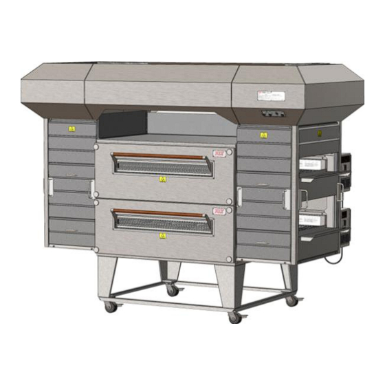
Page 8: Oven & Hood Descriptions
DESCRIPTIONS This manual covers the following XLT Oven & AVI Hood models: Ovens Hoods Standard World Standard World XLT-1832C-S XLT-1832C-W AVI-1832B-S AVI-1832B-W XLT-2440C-S XLT-2440C-W AVI-2440B-S AVI-2440B-W XLT-3240C-S XLT-3240C-W AVI-3240B-S AVI-3240B-W XLT-3255C-S XLT-3255C-W AVI-3255B-S AVI-3255B-W XLT-3270C-S XLT-3270C-W AVI-3270B-S AVI-3270B-W XLT-3855C-S XLT-3855C-W AVI-3855B-S AVI-3855B-W XLT-3870C-S... - Page 9 OVEN DESCRIPTION Sandwich Door Oven Lid Conveyor Control Box Crumb Tray Front Panel Knob Product Stop Locking Front Panel Swivel Caster Data Plate Control Box Lid Control Switch Control Panel Chain Guard Technical Support US: 888-443-2751 Technical Support INTL: 316-943-2751...
-
Page 10: Oven Dimensions & Weights
OVEN DIMENSIONS Technical Support US: 888-443-2751 Technical Support INTL: 316-943-2751... - Page 11 OVEN DIMENSIONS & WEIGHTS SINGLE WEIGHT STACK 47 1/4 67 1/4 42 3/4 1832 [457] [813] [1200] [1778] [1708] [1086] [813] [216] 53 1/4 75 1/4 42 3/4 2440 [610] [1016] [1353] [1981] [1911] [1086] [813] [246] 61 1/4 75 1/4 42 3/4 3240 [813]...
-
Page 12: Oven Gas Requirements
OVEN GAS REQUIREMENTS All values shown this page are per each oven Gas Oven Heating Values & Orifice Sizes Heating Values Orifice Sizes Oven Australian Standard & World Australian Standard & World Model All Fuels MJ/HR KW/HR BTU/HR KW/HR MM MM Inches Inches 1832 17.5... - Page 13 OVEN GAS REQUIREMENTS World Oven Gas Group Natural Gas Propane Gas Gas Group 3B/P (30) 3P (30/37/50) 3B (37) Inlet pressure (mbar) 20 20/25 25 28/30/37/50 28-30/37/50 30/37/50 (1) per burner Number of injectors Fixed Main burner opening size Electric Direct Spark Igniter Ignition BSP 3/4"...
- Page 14 OVEN GAS REQUIREMENTS Gas Supply Requirements for Australian, Standard. & World Ovens All installations must conform to local building & mechanical codes. NOTE 1. The gas supply shall have a gas meter & regulator large enough to handle ALL of the gas ap- pliances, such as the furnace, water heater, &...
- Page 15 OVEN GAS REQUIREMENTS Gas Supply Testing Requirements 1. The appliance & its individual shutoff valve must be disconnected from the gas supply piping system during any pressure testing of that system at test pressures in excess of 3.5 kPa or ½- psi.
-
Page 16: Oven Electrical Requirements
OVEN ELECTRICAL REQUIREMENTS All values shown this page are per each oven Gas Oven Electrical Requirements Per EACH Oven STANDARD WORLD Oven Model Volts AC Amps Hertz Volts AC Amps Hertz 1832 2440 220/230/ 3240 120 VAC 240 VAC 3255 1Φ... -
Page 17: Oven Only Rough-In Specifications
OVEN ONLY ROUGH-IN SPECIFICATIONS 6.00 [152] From back of oven to wall Utilities must be easily accessible when the ovens are in the installed position. Do not install utilities behind the ovens. NOTE 3.00 [76] 6.00 [152] Electrical Supply Gas Manifold 48.00 [1219] 42.00... -
Page 18: Oven Assembly
OVEN ASSEMBLY Base Assembly - Triple Stack Technical Support US: 888-443-2751 Technical Support INTL: 316-943-2751... - Page 19 OVEN ASSEMBLY Base Assembly - Single & Double Stack Technical Support US: 888-443-2751 Technical Support INTL: 316-943-2751...
- Page 20 OVEN ASSEMBLY WARNING & SAFETY INFORMATION XLT ovens can easily be moved and stacked with the proper lifting equipment. The use of XLT approved lifting equipment is highly recommended. Contact XLT for more information. These ovens are heavy & can tip or fall causing bodily injury.
- Page 21 OVEN ASSEMBLY The Lifting Pipe hole, marked for the appropriate oven size, must be installed closest to the control box. NOTE Technical Support US: 888-443-2751 Technical Support INTL: 316-943-2751...
- Page 22 OVEN ASSEMBLY Stacking the Ovens Failure to engage the Lifting Jacks into the Lifting Pipe properly and completely will result in damage, injury, or death from a falling oven. WARNING Both jacks should be raised in unison, otherwise they may bind and a dangerous situation will develop.
- Page 23 OVEN ASSEMBLY Stacking the Ovens Technical Support US: 888-443-2751 Technical Support INTL: 316-943-2751...
-
Page 24: Oven Installation
OVEN INSTALLATION Physical Location & Spacing Requirements These ovens are suitable for installation on either combustible or non-combustible floors, and adjacent to either combustible or non-combustible walls. The motor cover is designed to pro- vide the proper clearance to the back of the oven. The minimum side clearances are 6in. / 150mm, measured from the end of the conveyor. -
Page 25: Oven Fire Suppression
OVEN FIRE SUPPRESSION The requirement for fire suppression systems vary by location and the authority having ju- risdiction. If you are required to install fire suppression on your oven, a pre-assembled piping kit is available that utilizes pre-existing holes that simplify installation and future service. This design has been tested and approved to successfully comply with fire suppression codes. - Page 26 OVEN FIRE SUPPRESSION Technical Support US: 888-443-2751 Technical Support INTL: 316-943-2751...
-
Page 27: Oven Ventilation Requirements & Guidelines
Requirements vary throughout the country depending upon location. Proper ventilation is the oven owner’s responsibility. The AVI Hood system is designed to meet all requirements for XLT ovens and it is our recommendation that this system be used. -
Page 28: Oven Initial Start-Up
The Oven Initial Start-Up Checklist, found at the end of this manual, must be completed (both sides) at time of installation, signed by the Customer and returned to XLT Ovens and the Au- thorized Distributor to initiate Warranty Policy. -
Page 29: Oven Operation
OVEN OPERATION This oven is not capable of being safely placed in operation in the event of a power failure. No attempt should be made to operate this oven during power failure. CAUTION Set Point Actual Temperature Control Push and Hold Conveyor Control Push and Hold Conveyor Belt Times (Min:Sec) -
Page 30: Oven Operator Controls
OVEN OPERATOR CONTROLS Conveyor Speed Controls Control Panel Split Belt Temperature Control Circuit Breakers Fan & Filter Control Panel Standard Belt Technical Support US: 888-443-2751 Technical Support INTL: 316-943-2751... -
Page 31: Oven Cleaning
& can be washed several times. Regular cleaning of the filter is important to maintain air circulation within the control box. Depending upon store conditions, this filter should be cleaned weekly or as it gets clogged with dust. Please contact XLT Ovens for replacement parts. - Page 32 OVEN CLEANING Opening the Sandwich Door will provide a grip location for removing the Front Panel. Front Panels can weigh up to 75 lbs. [34 kg]. Use caution when lifting. CAUTION Technical Support US: 888-443-2751 Technical Support INTL: 316-943-2751...
- Page 33 OVEN CLEANING Technical Support US: 888-443-2751 Technical Support INTL: 316-943-2751...
- Page 34 OVEN CLEANING DO NOT spray liquid cleaning agents in the slots and holes in the following loca- tions: Rear of Control Box Underneath Control Box CAUTION Main Fan Motor Cover Technical Support US: 888-443-2751 Technical Support INTL: 316-943-2751...
-
Page 35: Oven Maintenance
OVEN MAINTENANCE As with any appliance, periodic maintenance is required. Many factors affect this schedule such as product mix and hours of usage. An example schedule is included. Oven Maintenance Schedule Semi- Daily Weekly Monthly Annual Cleaning □ Empty Crumb Trays □... -
Page 36: Oven Troubleshooting
8. Raw ingredient temperature (frozen?) 9. Quantity of toppings XLT ovens can be configured to cook a wide variety of food items. This is accomplished by arranging the fingers to control the baking characteristics. Generally speaking, most cooking is a “bottom up” process. The hot air from the bottom row of fingers has to go through the conveyor (a distance of about 2”... - Page 37 OVEN TROUBLESHOOTING Mechanical Function If your oven does not function properly, please verify the following conditions: 1. Verify that the power cord to the oven is connected and/or plugged in if equipped with a plug and receptacle. 2. Check to see that the circuit breakers in the building electrical service panel have not been tripped or turned off.
- Page 38 AVI HOOD INSTALLATION Check all local codes prior to installation. Special requirements may be necessary depending upon building material construction. It is the installing contractor’s re- sponsibly to ensure that the structure the hood is to be hung from meets all codes WARNING and can carry the hood weight.
-
Page 39: Hood Description
AVI EXHAUST HOOD HOOD DESCRIPTION Main Canopy VFD Exhaust Fan Controller Front Shroud End Shroud Panel Panel The AVI Hood System consists of three (3) major parts; the Main Canopy, the Shrouds, and the Variable Frequency Drive (VFD) exhaust fan controller. The Main Canopy serves to collect and transmit heat to the exhaust fan. -
Page 40: Hood Dimensions & Weights
AVI HOOD DIMENSIONS Technical Support US: 888-443-2751 Technical Support INTL: 316-943-2751... - Page 41 AVI HOOD DIMENSIONS & WEIGHTS Oven Hood Dimensions Hood Weights Model Single Double Triple 34 3/8 88 5/8 30 5/8 1832 [873] [2251] [457] [813] [778] [245] [227] [238] 40 3/8 96 5/8 33 5/8 2440 [1026] [2454] [610] [1016] [854] [281] [259]...
-
Page 42: Hood Electrical Requirements
AVI HOOD ELECTRICAL REQUIREMENTS Inputs into VFD Box AVI Hood Electric Utility Specifications # of Circuits Rating Purpose 230 VAC, 1 Phase, 50 Hz, 3 Amp VFD Controller Australian 230 VAC, 1 Phase, 50 Hz, 1 Amp Lights 208/240 VAC, 3 Phase, 60 Hz, 3 Amp VFD Controller Standard 120 VAC, 1 Phase, 60 Hz, 1 Amp... - Page 43 AVI HOOD ELECTRICAL DESCRIPTION VFD Control Box - Standard Terminal Strip (TS1) Grounding Block Terminal Strip (TS2) Manual Mode MUA Damper Relay Relay (R5) (R1) Manual Mode MUA Damper Relay Relay (R6) (R2) Manual Mode MUA Damper Relay Relay (R7) (R3) Fire Suppression Fire Suppression Relay...
-
Page 44: Hood Electrical Connections
AVI HOOD ELECTRICAL CONNECTIONS Input Power to VFD Controller - Standard Voltage & Frequency Technical Support US: 888-443-2751 Technical Support INTL: 316-943-2751... - Page 45 AVI HOOD ELECTRICAL CONNECTIONS Input Power to Lights with VFD- Standard Voltage & Frequency Technical Support US: 888-443-2751 Technical Support INTL: 316-943-2751...
- Page 46 AVI HOOD ELECTRICAL CONNECTIONS Power from VFD to Exhaust Fan - Standard Voltage & Frequency Technical Support US: 888-443-2751 Technical Support INTL: 316-943-2751...
- Page 47 AVI HOOD ELECTRICAL CONNECTIONS Fire Alarm Relay - Standard Voltage & Frequency Technical Support US: 888-443-2751 Technical Support INTL: 316-943-2751...
- Page 48 AVI HOOD ELECTRICAL CONNECTIONS MUA Damper Relays - Single Output - Standard Voltage & Frequency MUA Unit Relay Power Power Neutral Supply from Breaker Panel 10 Amperes Maximum TS 1 TS 2 Some wiring removed for clarity. See schematic for details. Technical Support US: 888-443-2751 Technical Support INTL: 316-943-2751...
- Page 49 AVI HOOD ELECTRICAL CONNECTIONS MUA Damper Relays - Multiple Output - Standard Voltage & Frequency MUA Unit Relay MUA Unit Relay MUA Unit Relay Power Power Power Power Power Power Neutral Supply from Breaker Panel 10 Amperes Maximum TS 1 TS 2 Some wiring removed for clarity.
- Page 50 AVI HOOD ELECTRICAL CONNECTIONS VFD Control Box - World Terminal Strip (TS1) Grounding Block Terminal Strip (TS2) Hood Fire Suppression Relay (R4) MUA Damper Relay Oven Fire Suppression (R1) Relay (R5) MUA Damper Relay Oven Fire Suppression (R2) Relay (R6) MUA Damper Relay Oven Fire Suppression (R3)
- Page 51 AVI HOOD ELECTRICAL CONNECTIONS Input Power to VFD Controller - World Voltage & Frequency Technical Support US: 888-443-2751 Technical Support INTL: 316-943-2751...
- Page 52 AVI HOOD ELECTRICAL CONNECTIONS Output Power from VFD to Exhaust Fan - World Technical Support US: 888-443-2751 Technical Support INTL: 316-943-2751...
- Page 53 AVI HOOD ELECTRICAL CONNECTIONS Fire Alarm Relay - World (optional) Technical Support US: 888-443-2751 Technical Support INTL: 316-943-2751...
- Page 54 AVI HOOD ELECTRICAL CONNECTIONS MUA Damper Relays - Single Output - World Voltage & Frequency MUA Unit Relay Power Power Neutral Supply from Breaker Panel 10 Amperes Maximum TS 1 TS 2 Some wiring removed for clarity. See schematic for details. Technical Support US: 888-443-2751 Technical Support INTL: 316-943-2751...
- Page 55 AVI HOOD ELECTRICAL CONNECTIONS MUA Damper Relays - Multiple Output - World Voltage & Frequency MUA Unit Relay MUA Unit Relay MUA Unit Relay Power Power Power Power Power Power Neutral Supply from Breaker Panel 10 Amperes Maximum TS 1 TS 2 Some wiring removed for clarity.
- Page 56 AVI HOOD ELECTRICAL CONNECTIONS Input Power to Lights - Without VFD Controller Terminal Strip (TS1) Grounding Block Oven/hood interface Non-VFD Control Box (Cover removed) Technical Support US: 888-443-2751 Technical Support INTL: 316-943-2751...
-
Page 57: Hood Rough-In Specifications
AVI HOOD ROUGH-IN SPECIFICATIONS All structural members, electrical & fire suppression equipment shown for reference only. Technical Support US: 888-443-2751 Technical Support INTL: 316-943-2751... -
Page 58: Hood Exhaust Flow Rates
AVI RECOMMENDED EXHAUST FLOW RATES Exhaust Flow Rates VOLUME (min. recommended) Switches On 18xx 24xx 32xx 38xx Top Middle Bottom Single [14.16] [14.16] [14.16] [14.16] [14.16] [14.16] [14.16] [14.16] Double [14.33] [18.24] [23.45] [27.35] [14.33] [18.24] [23.45] [27.35] [14.16] [14.16] [14.16] [14.16] [14.33]... - Page 59 AVI RECOMMENDED EXHAUST FLOW RATES Exhaust Flow Rates VELOCITY (min. recommended) Switches On 18xx 24xx 32xx 38xx Top Middle Bottom 187.5 187.5 93.75 93.75 Single [57.15] [57.15] [28.58] [28.58] 187.5 187.5 93.75 93.75 [57.15] [57.15] [28.58] [28.58] 189.75 241.5 155.25 181.125 Double [57.84]...
-
Page 60: Hood Installation
AVI HOOD INSTALLATION Prepare Ovens - Remove Lid Screws - Two (2) Only Prepare Ovens - Control Box Closeout Bracket Conveyors have been removed for clarity Technical Support US: 888-443-2751 Technical Support INTL: 316-943-2751... - Page 61 AVI HOOD INSTALLATION Prepare Ovens - Front Shroud Brackets Technical Support US: 888-443-2751 Technical Support INTL: 316-943-2751...
- Page 62 AVI HOOD INSTALLATION Prepare Ovens - Bottom Rail Bracket Prepare Ovens - Control Box Side Closeout Technical Support US: 888-443-2751 Technical Support INTL: 316-943-2751...
- Page 63 AVI HOOD INSTALLATION Prepare Ovens - Rear Shroud Brackets Technical Support US: 888-443-2751 Technical Support INTL: 316-943-2751...
- Page 64 AVI HOOD INSTALLATION Prepare Hood Technical Support US: 888-443-2751 Technical Support INTL: 316-943-2751...
- Page 65 AVI HOOD INSTALLATION Lifting Gear Setup AVI hoods can easily be moved and stacked with the proper lifting equipment. The use of XLT approved lifting equipment is highly recommended. Contact XLT for more information. Technical Support US: 888-443-2751 Technical Support INTL: 316-943-2751...
- Page 66 AVI HOOD INSTALLATION Lifting Jack Setup Check for smooth operation. The cable should not be pinched & should pass smoothly over the pulley on top of the pole assembly. Inspect cable prior to each use. If cable is frayed or shows signs of excessive wear & tear, DO NOT USE until cable is replaced.
- Page 67 AVI HOOD INSTALLATION Stacking Hood on the Ovens Failure to engage the Lifting Jacks into the Lifting Pipe properly and completely will result in damage, injury, or death from a falling hood. WARNING Both jacks should be raised in unison, otherwise they may bind and a dangerous situation will develop.
- Page 68 AVI HOOD INSTALLATION Hang Hood From Ceiling Joists All thread provided by others 69 5/8 ±1/8 Technical Support US: 888-443-2751 Technical Support INTL: 316-943-2751...
- Page 69 AVI HOOD INSTALLATION Install Grease Trays, Light Bulbs & Covers, and Grease Filters Grease Tray Filler Panel to be Grease Filters Technical Support US: 888-443-2751 Technical Support INTL: 316-943-2751...
- Page 70 AVI HOOD INSTALLATION Install Shroud Hanging Brackets Technical Support US: 888-443-2751 Technical Support INTL: 316-943-2751...
- Page 71 AVI HOOD INSTALLATION Install Corner Posts Technical Support US: 888-443-2751 Technical Support INTL: 316-943-2751...
- Page 72 AVI HOOD INSTALLATION Install Bottom Rails Technical Support US: 888-443-2751 Technical Support INTL: 316-943-2751...
- Page 73 AVI HOOD INSTALLATION Install Bottom Rails Technical Support US: 888-443-2751 Technical Support INTL: 316-943-2751...
- Page 74 AVI HOOD INSTALLATION Install Control Box Upper Closeout Technical Support US: 888-443-2751 Technical Support INTL: 316-943-2751...
- Page 75 AVI HOOD INSTALLATION Install Shroud Panels - Front and Ends Technical Support US: 888-443-2751 Technical Support INTL: 316-943-2751...
- Page 76 AVI HOOD INSTALLATION Install Back Shroud Panel Technical Support US: 888-443-2751 Technical Support INTL: 316-943-2751...
- Page 77 AVI HOOD INSTALLATION Install Hood Control Cord Assembly All hoods are outfitted with three (3) control cord outlets, regardless of how many XLT Ovens are installed. For a single oven use “Top” location. For a double stack use “Top” location for upper oven and “Bottom”...
- Page 78 AVI HOOD INSTALLATION Connect Hood Control Cord Assembly Technical Support US: 888-443-2751 Technical Support INTL: 316-943-2751...
-
Page 79: Hood Initial Start-Up
The Initial Start-Up Checklist must be completed at time of installation, signed by the Cus- tomer and returned to XLT Ovens to initiate Warranty Policy. The VFD controller is adjusted at the factory to the values displayed in the chart below. -
Page 80: Hood Operator Controls
The control switches are located on the front of the hood. When XLT Ovens are outfitted with AVI Hoods, the main switch on the oven is dis- abled and no longer operates. The switch on the AVI Hood overrides the oven switch. -
Page 81: Hood Valance Kit
AVI HOOD VALANCE KIT (OPTIONAL) The valance kit size is determined by AVI Hood size & distance from the finished floor to the installed drop ceiling height. The valance kit screws directly to the AVI Hood & does not re- quire any structural support. - Page 82 AVI HOOD VALANCE KIT (OPTIONAL) Install Valance Brackets Install Front & Back Panels Technical Support US: 888-443-2751 Technical Support INTL: 316-943-2751...
- Page 83 AVI HOOD VALANCE KIT (OPTIONAL) Install Corner Panels Install End Panels Technical Support US: 888-443-2751 Technical Support INTL: 316-943-2751...
-
Page 84: Hood Duct Wrap Kit
AVI DUCT WRAP KIT (OPTIONAL) Technical Support US: 888-443-2751 Technical Support INTL: 316-943-2751... -
Page 85: Hood Cleaning
AVI HOOD CLEANING Your AVI hood is constructed of stainless and aluminized steel. Check application restric- tions on product label prior to usage. Observe recommended precautionary and safety measures as dictated by the product manufacturer. Do not use abrasive or caustic cleaners. Abrasive pads will scratch stainless steel surfaces. Areas with heavy buildup should be sprayed and allowed to soak for up to 5 minutes prior to wip- ing clean. -
Page 86: Hood Troubleshooting
AVI HOOD TROUBLESHOOTING Before troubleshooting the hood: 1. Make sure that the RUN lamp and POWER lamp are lit. 2. Check to see that the breaker in the service panel is not tripped. 3. Check to see that the breaker on the hood electrical box is not tripped. 4. -
Page 87: Variable Frequency Drive Manual Mode
AVI VARIABLE FREQUENCY DRIVE (VFD) MANUAL MODE Standard Hoods ONLY The manual mode feature was designed to offer temporary operation of the exhaust fan at full power if the VFD controller fails. Manual mode should not be used for normal day-to-day op- eration and should only be utilized during emergency situations. -
Page 88: Electrical Schematics
OVEN SCHEMATIC - STANDARD 1 BOX Technical Support US: 888-443-2751 Technical Support INTL: 316-943-2751... - Page 89 OVEN SCHEMATIC - WORLD 1 BOX Technical Support US: 888-443-2751 Technical Support INTL: 316-943-2751...
- Page 90 OVEN SCHEMATIC - STANDARD 2 BOX LH Technical Support US: 888-443-2751 Technical Support INTL: 316-943-2751...
- Page 91 OVEN SCHEMATIC - STANDARD 2 BOX RH Technical Support US: 888-443-2751 Technical Support INTL: 316-943-2751...
- Page 92 OVEN SCHEMATIC - WORLD 2 BOX LH Technical Support US: 888-443-2751 Technical Support INTL: 316-943-2751...
- Page 93 OVEN SCHEMATIC - WORLD 2 BOX RH Technical Support US: 888-443-2751 Technical Support INTL: 316-943-2751...
- Page 94 AVI HOOD SCHEMATIC - STANDARD w/VFD Technical Support US: 888-443-2751 Technical Support INTL: 316-943-2751...
- Page 95 AVI HOOD SCHEMATIC - WORLD w/VFD Technical Support US: 888-443-2751 Technical Support INTL: 316-943-2751...
- Page 96 AVI HOOD SCHEMATIC w/o VFD Technical Support US: 888-443-2751 Technical Support INTL: 316-943-2751...
-
Page 97: Certifications
APPENDIX A Product Certifications and Applicable Codes Standard XLT Oven Certifications ¹: XLT Gas Ovens: 1. ANSI Z8311-2006/CSA 1.8-2006 Standard for Gas Food Service Equipment 2. ANSI /NSF 4-2006e Sanitation for Commercial Cooking Rethermillization & Powered Hot Food Holding & Transportation Equipment XLT Electric Ovens: 1. - Page 98 2. AS/NZS 3350.1:2002 Safety of Household & Similar Electrical Appliances. ¹ The noted certifications for XLT ovens and AVI Hood are performed and documented by Intertek Testing Services NA Inc. 165 Main Street, Cortland, NY 13045. Intertek is a nationally and internationally certified testing and accreditation agency.
-
Page 99: Oven Start-Up Checklist
Oven Initial Start-up Checklist - Remove & Return to XLT Ovens Oven Size: 1832 1855 2440 3240 Date of installation: _____________________________ 3255 3270 3855 3870 Installed by: XLT installer: ____________... - Page 100 Oven Initial Start-up Checklist - Remove & Return to XLT Ovens...
-
Page 101: Hood Start-Up Checklist
Hood Initial Start-up Checklist - Remove & Return to XLT Ovens Model #: Serial #: VFD power supplied: Oven switch cords connected to VFD box: Volts Amps Lights operate with switch: Phase Light globes installed over bulbs: Height from bottom of hood to finished floor: ... - Page 102 XLT Ovens PO Box 9090 Wichita, Kansas 67277 US: 888-443-2751 FAX: 316-943-2769 INTL: 316-943-2751 WEB: www.xltovens.com...
Need help?
Do you have a question about the XLT Gas Oven and is the answer not in the manual?
Questions and answers