Table of Contents
Advertisement
Quick Links
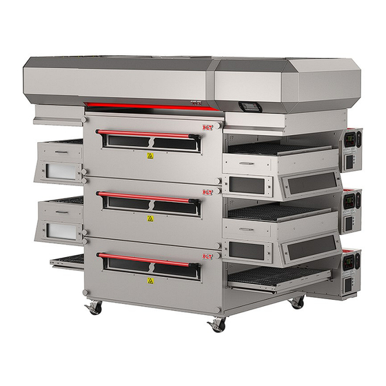
XLT Electric Oven & XLT Hood
Read This Manual Before Using This Appliance.
CAUTION
Electronic copies of this manual, Technical Specifications, Installation & Operation Manual, Architectural Drawings,
& a list of International Authorized Distributors are available at:
For use with the following XLT Electric Oven Versions:
Standard (S)
H
World (W)
H
Original Instructions
US: 888-443-2751 FAX: 316-943-2769
Parts & Service Manual
For use with the following XLT Electric Hood Versions:
Standard (S)
World (W)
2000887
XLT Ovens
PO Box 9090
Wichita, Kansas 67277
INTL: +1-316-943-2751
SWH03HF02
www.xltovens.com
F
F
WEB:
www.xltovens.com
XD 9007A
5/9/2023
Advertisement
Table of Contents
Troubleshooting

Related Manuals for XLT Ovens XP-5201-208-4.5


Summary of Contents for XLT Ovens XP-5201-208-4.5
- Page 1 For use with the following XLT Electric Oven Versions: For use with the following XLT Electric Hood Versions: Standard (S) Standard (S) World (W) World (W) 2000887 XLT Ovens PO Box 9090 Original Instructions Wichita, Kansas 67277 US: 888-443-2751 FAX: 316-943-2769 INTL: +1-316-943-2751 WEB:...
-
Page 2: Warning & Safety Information
WARNING & SAFETY INFORMATION FOR YOUR SAFETY Do not store or use gasoline or other flammable vapors and liquids on the vi- WARNING cinity of this or any other appliance. Improper installation, adjustment, alteration, service or maintenance can cause property damage, injury, or death. Read the installation, operating and maintenance instructions thoroughly before installing or servicing this WARNING equipment. - Page 3 WARNING & SAFETY INFORMATION Definitions & Symbols A safety instruction (message) includes a “Safety Alert Symbol” & a signal word or phrase such as DANGER, WARNING or CAUTION. Each signal word has the following meaning: ISO 7000-0434: This symbol indicates a potentially hazardous situation that, if not avoided, can result in serious injury or death.
- Page 4 Appliance is not to be cleaned with water jet (high pressure water). Most XLT ovens are certified for use in stacks of up to four (4) units of XLT products. Inte- gration of other manufacturer’s products into an oven stack is not recommended, and voids any warranties.
-
Page 5: Table Of Contents
TABLE OF CONTENTS Warning & Safety Information......................2 Table of Contents ..........................5 General ............................... 6 Warranty ............................. 8 Installation Responsibilities ......................10 Oven Theory of Operation ....................... 11 Hood Theory of Operation ....................... 18 Oven Troubleshooting ........................23 Hood Troubleshooting ........................25 Oven Service Procedures........................ -
Page 6: General
GENERAL This manual, which contains an illustrated parts breakdown, has been prepared as an aid in understanding how the unit operates, how to diagnose problems, and order parts for the equipment. All of the parts, listed in the parts breakdown, are manufactured with the same precision as the original equipment. - Page 7 GENERAL Save this Manual This document is the property of the owner of this equipment. XLT reserves the right to make changes in design & specifications, and/or make additions to or improvements to its product without imposing any obligations upon itself to install them in products previously manufactured.
-
Page 8: Warranty
Warranty – US and Canada Rev J Approval Date: 09/22/2022 XLT warrants ovens manufactured after September 22, 2022 to be free from any defect in ma- terial and workmanship under normal use for seven (7) years from the date of original purchase by the end user, and further warrants main fan blades, conveyor shafts, and conveyor bearings for ten (10) years. - Page 9 Warranty – International Rev L Approval Date: 09/22/2022 XLT warrants ovens manufactured after September 22, 2022 to be free from any defect in material and workmanship under normal use for five (5) years from the date of original purchase by the end user, and further warrants main fan blades, conveyor shafts, and conveyor bearings for ten (10) years.
-
Page 10: Installation Responsibilities
INSTALLATION RESPONSIBILITIES Owner/ Responsibility Service Company Contractor Site Survey: Verify electric and gas meter/regulator sizes Supply wiring from TS1 #R3, R4, R5 to exhaust fan Assembly of new hood per XLT Installation & Operation Manual Suspend XLT Hood from ceiling Weld ducting to XLT Hood Install new exhaust fan on roof Supply power to XLT Hood... -
Page 11: Oven Theory Of Operation
OVEN THEORY OF OPERATION Legend from electrical schematics: Contactor Oven Machine Control Solid State Relay Capacitor Power Block Thermocouple Circuit Breaker Push Lock Terminal Strip Current Sensor Power Supply Variable Frquency Drive Heating Element Pick-Up Wago Connector Filter, Control Voltage Oven Fan Motor Relay Large User Interface RTD, High Limit... - Page 12 H1-H6 - The Heating Elements convert electricity into heat through the process of joule heating. Electric current through the element encounters resistance, resulting in heating the element. The resistance values of the four (4) different part numbers used are: XP-5201-208-4.5 4500 Watt 9.61 Ohms XP-5201-240-4.5 4500 Watt 12.80 Ohms...
- Page 13 OVEN THEORY OF OPERATION 1) P1- Not Used 2) P2- RS-485 Cable To OMC1 1) +5V 2) 485- 3) 485+ 4) Ground 3) P3- RS-485 Cable To OMC2 1) +5V 2) 485- 3) 485+ 4) Ground 4) P5- Ground 5) P17- Elan Programming LUI - The Large User Interface is powered by the OMC by the RS 485 cable.
- Page 14 OVEN THEORY OF OPERATION M2 - The Conveyor Motor is a brushless 24 VDC gear motor. The motor receives current from the OMC through three (3) wires; 1) A “W” phase, 2) a “V” phase, and 3) an “U” phase. They carry between 18 to 24 VDC.
- Page 15 OVEN THEORY OF OPERATION PB - The Power Block is a connection point for multiple wires of different gauges. 1) CN2- 24VDC 1) +24 VDC Main Power To OMC 2) +24 VDC 3) +24 VDC 4) -24 VDC Ground To TS2- 2) CN1- Line Voltage 1) Neutral 2) Not Used...
- Page 16 OVEN THEORY OF OPERATION 1) COM– Line Voltage 2) N.O.- Switched Line Voltage 3) L2- High Limit Power 4) L1- High Limit Power 5) RTD S3 - World Ovens- The High Limit Switch is an electronic, SPST switch. Its purpose is to provide fail safe operation.
- Page 17 OVEN THEORY OF OPERATION 1) Incoming Power 1) Neutral (L1) 2) Line Voltage (L2) 3) Not Used (L3) 4) Ground 2) Digital Inputs 1) Not Used 2) Start / Run 3) Stop Function 4) Not Used 5) Not Used 6) Not Used 7) COM To TS2 3) Main/Exhaust Fan Power 1) Ground...
-
Page 18: Hood Theory Of Operation
HOOD THEORY OF OPERATION (STD W/FS) Legend from electrical schematics: Circuit Breaker Motor, Cooling Fan Switch Hood Machine Control Power Supply Switch Relocation Cord Hood User Interface Fire Suppression Relay Terminal Strip Lamp Fire Suppression Time Delay Variable Frequency Drive Motor, Exhaust Fan Relay Motor, Cooling Fan... - Page 19 HOOD THEORY OF OPERATION (STD W/FS) Part 2: CB - Circuit Breakers are used to protect electrical components. If a CB is tripped, eliminate the cause and press the front to reset. 1) P1- Dampers 5) P9- Power 1) MUA Top 1) +24 VDC Power 2) Not Used Supply CN2-1...
- Page 20 HOOD THEORY OF OPERATION (STD W/FS) XLT Logo Exhaust Fan Speed Oven Off (Outline) Exhaust Fan On Oven On (Filled) Hood Lights Alarm Mute Error Information Oven Buttons HUI - Hood User Interface contains the factory settings so that the hood will operate with the cor- rect hertz when the correct oven size and number of ovens are selected.
- Page 21 HOOD THEORY OF OPERATION (STD W/FS) 1) CN2- 24VDC 1) +24 VDC Power To HMC 2) +24 VDC Power to Fire Suppression 3) -24 VDC Power To HMC 4) -24 VDC Ground 2) CN1- Line Voltage 1) Neutral 2) Not Used 3) Line Voltage PS - The Power Supply rectifies line voltage to 24 VDC, and supplies power to the HMC, cooling fans, and fire suppression.
- Page 22 HOOD THEORY OF OPERATION (STD W/FS) 1) Incoming Power 1) Neutral 2) Line Voltage 3) Not Used 4) Ground 2) Not Used-VFD Relay 3) Digital Inputs 1) Stop Function 2) Start / Run 3) Not Used 4) COM To TS2 5) Not Used 6) Not Used 4) Exhaust Fan Power...
-
Page 23: Oven Troubleshooting
OVEN TROUBLESHOOTING Mechanical Function If your oven does not function properly, please verify the following conditions: 1. Verify that the power cord to the oven is connected and/or plugged in if equipped with a plug and receptacle. 2. Check all circuit breakers on the oven control panel and on the back of the control box to en- sure they have not been tripped. - Page 24 OVEN TROUBLESHOOTING LUI Service Error Codes Display Alarm MC LED Error Determination Troubleshooting Alarm LED on. Flash HEAT Temp Sensor Error, Open or Short. Perform A Hard Reset. If Error Still Exists, Oven Probe LED. All other LED's operate Temp <40F (4C) or >700F (371C) Contact XLT.
-
Page 25: Hood Troubleshooting
HOOD TROUBLESHOOTING Removing the hood VFD cover panel exposes high voltage. Proceed with caution and read the following instructions carefully. HIGH VOLTAGE Initial troubleshooting of the hood 1. Remove panel covering VFD to check and see if the circuit breaker is tripped. 2. - Page 26 HOOD TROUBLESHOOTING The VFD has internal diagnostics, and may show the following ERROR codes: F004 DC bus voltage fell below minimum value F005 DC bus voltage exceeded maximum value F007 Motor Overload F008 Heat sink Over Temp ...
-
Page 27: Oven Service Procedures
OVEN SERVICE PROCEDURES Read the entire instruction before programming. ENTER Used to select and save parameters. Increases the setting of the selected param- eter. DOWN Decrease the setting of the selected param- eter. To enter factory tech mode press both UP and DOWN button simultaneously for ten (10) seconds and the following parameters will be displayed: *Displays will auto-exit programming screens af- ter five (5) seconds of no activity. - Page 28 OVEN SERVICE PROCEDURES Conveyor Speed Settings Read the entire instruction before programming. ENTER Used to select and save parameters. HIDDEN Behind the XLT is a hidden button. This is used along with the up and down button to access the programming mode. Increases the setting of the selected pa- rameter.
- Page 29 OVEN SERVICE PROCEDURES Directional Change of the Conveyor Belt The conveyor belt is non-directional. This means there is NO physical change of the belt when wanting to change direction. To change the direction: Standard Belt 1. Enter Factory Tech Mode by pressing and holding the two (2) arrow buttons for ten (10) seconds.
- Page 30 OVEN SERVICE PROCEDURES Invertek VFD (World) Programming Procedure Read the entire instruction before programming. When in keypad mode, used to Start a stopped START drive or to reverse the direction of rotation if bi -directional keypad mode is enabled. Used to increase speed in real-time mode or to increase parameter values in parameter edit mode.
- Page 31 OVEN SERVICE PROCEDURES Read the entire instruction before programming. Programming Instructions For Lower Than 60 Hz 1. Press and hold NAVIGATE for > 2 seconds. 2. Press UP Arrow until (P-38) is displayed and press NAVIGATE. 3. Press DOWN Arrow until (0) is displayed and press NAVIGATE to save and return to parame- ter menu.
-
Page 32: Hood Service Procedures
HOOD SERVICE PROCEDURES Allen Bradley Power Flex 4M Restoring XLT Hood Defaults Read the entire instruction before programming. To reset VFD settings change P112 to one (1) . The VFD will reset to factory default settings. To cycle power, turn circuit breaker off and on and the HMC will load the factory parameters into the VFD. - Page 33 HOOD SERVICE PROCEDURES The VFD controller is adjusted at the factory to the values displayed in the chart below. VFD Controller Settings Ovens On 3240, 3250DS & 1832, 2336 & 2440 3855 4455 Top Middle Bottom 3255 Single 20 Hz 25 Hz 30 Hz 30 Hz...
-
Page 34: Parts Ordering
PARTS ORDERING How To Order Parts Have all information ready when calling XLT. Below is a list of information that is re- quired for all orders. At the bottom of the Bill of Materials (BOM) on the following parts overview pages are additional requirements needed depending on your parts order. -
Page 35: Oven Parts
OVEN PARTS - OVERVIEW Technical Support US: 888-443-2751 Technical Support INTL: +1-316-943-2751... - Page 36 OVEN PARTS - FRONT PANEL Individuals with pacemakers or internal medical devices should not handle strong rare-earth magnets. These magnets are found in the sandwich door assembly. WARNING All Components From This Page FRONT PANEL ITEM PART NUMBER DESCRIPTION XA 6400 Front Panel XA 6500 Front Panel Assembly...
- Page 37 OVEN PARTS - FRONT PANEL EXTENDED FRONT PANEL ITEM PART NUMBER DESCRIPTION XA 6700 Extended Front Panel Front Panel information required: Size of Oven Short or Long Sandwich Door, or No Door Stainless, Wood, or Painted Handle Technical Support US: 888-443-2751 Technical Support INTL: +1-316-943-2751...
- Page 38 OVEN PARTS - BACK WALL Installed Fan Height 1832 and 2440 only 2336 only 9 1/16” 8 1/16” [231mm] [205mm] 11 3/8” [289mm] Technical Support US: 888-443-2751 Technical Support INTL: +1-316-943-2751...
- Page 39 OVEN PARTS - BACK WALL Electric Oven Elements 208V- 240V- 208V- 240V- Oven Size 4500W 4500W 5300W 5300W 1832-208 V 1832-240 V 1832-380 V 2336-208 V 2336-240 V 2336-380 V 2440-208 V 2440-240 V 2440-380 V 3240-208 V 3240-240 V 3240-380 V 3250-DS-208 V 3250-DS-240 V...
- Page 40 OVEN PARTS - CONVEYOR Standard Belt CONVEYOR ITEM PART NUMBER DESCRIPTION XA 7000 Conveyor Assembly Complete XA 7200 Conveyor Bearing Assembly XM 4006 Chain Guard Lower XM 7301 Conveyor Shaft Idle XM 7302 Conveyor Shaft Drive XM 9508 Chain Guard XP 7403 Conveyor Roll Notched XP 7404...
- Page 41 OVEN PARTS - CONVEYOR Split Belt CONVEYOR ITEM PART NUMBER DESCRIPTION XA 7000 Conveyor Assembly XA 7200 Conveyor Bearing Assembly XM 4006 Chain Guard Lower XM 7303 Conveyor Shaft Idle XM 7304 Conveyor Shaft Drive SB INSIDE XM 7305 Conveyor Shaft Drive SB OUTSIDE XM 9508 Chain Guard XP 7206...
- Page 42 OVEN PARTS - BASE Technical Support US: 888-443-2751 Technical Support INTL: +1-316-943-2751...
- Page 43 OVEN PARTS - BASE BASE ITEM PART NUMBER DESCRIPTION XA 1001 Base Assembly Bare XM 1003-15 Base Leg XM 1006 Side Leg Angle XM 1007 Front/Back Leg Angle XM 1008 Bolster Plate XM 1010 Oven Lid XP 1004 Caster Base information required: Size of Oven Single, Double, Triple, or Quad Stack Technical Support US: 888-443-2751...
- Page 44 OVEN PARTS - FINGER GROUP All Components From This Page Technical Support US: 888-443-2751 Technical Support INTL: +1-316-943-2751...
- Page 45 OVEN PARTS - FINGER GROUP FINGERS ITEM PART NUMBER DESCRIPTION XA 8Hxxxx Finger Group Assembly XA 8001-B Finger Body Bottom XA 8001-T Finger Body Top XM 8004 Finger Inner Plate Perforated XM 8024 Return Air Plate XM 8025 Endloss Plate XM 8xxx Finger Outer Plate Finger information required:...
- Page 46 OVEN PARTS - CONTROL BOX FRONT Standard Belt CONTROL BOX FRONT - Standard Belt ITEM PART NUMBER DESCRIPTION XA 4117A-ZD ST Conveyor Motor Assembly ZD Standard XP 4155A-12mm Sprocket Conveyor Drive 10T Control Box Front information required: Size of Oven Technical Support US: 888-443-2751 Technical Support INTL: +1-316-943-2751...
- Page 47 OVEN PARTS - CONTROL BOX FRONT Split Belt CONTROL BOX FRONT - Split Belt ITEM PART NUMBER DESCRIPTION XA 4117A-ZD SB Conveyor Motor Assembly ZD Split XA 4117A-ZD ST Conveyor Motor Assembly ZD Standard XP 4155A-12mm Sprocket Conveyor Drive 10T Control Box Front information required: Size of Oven Technical Support US: 888-443-2751...
- Page 48 OVEN PARTS - STANDARD CONTROL BOX Operating Position (shown with lid removed) Technical Support US: 888-443-2751 Technical Support INTL: +1-316-943-2751...
- Page 49 OVEN PARTS - STANDARD CONTROL BOX Service Position Technical Support US: 888-443-2751 Technical Support INTL: +1-316-943-2751...
- Page 50 OVEN PARTS - STANDARD CONTROL BOX CONTROL PANEL ITEM PART NUMBER DESCRIPTION SP 4520-EL Fan Guard / Filter Repl Kit ELE XP 4170-LUI Large User Inferface LUI XP 4175-MC Oven Machine Control OMC XP 4501-EL Cooling Fan EL M3 XP 4520-EL Fan Filter Control Panel information required: Size of Oven...
- Page 51 OVEN PARTS - STANDARD CONTROL BOX Image not shown CONTROL BOX INTERIOR ITEM PART NUMBER DESCRIPTION HP 2067-24VDC Oven Fan Motor Relay R1 XH-4117A-Elan Conveyor Motor Jumper Harness XP 4305-90 Solid State Relay, 90 Amp SSR XP 4305-90-COV Solid State Relay Cover XP 4305-90-HS Solid State Relay Heat Sink XP 4305-90-PAD...
- Page 52 OVEN PARTS - STANDARD CONTROL BOX CONTROL BOX REAR ITEM PART NUMBER DESCRIPTION XM 4052 Circuit Breaker Cover EL Bottom XM 4053 Circuit Breaker Cover EL Top XP 4302 Power Block Electric PB XP 4303 3 Pole Circuit Breaker EL CB XP 4515-CB Circuit Breaker CB XP 4707...
- Page 53 OVEN PARTS - WORLD CONTROL BOX Operating Position (shown with lid removed) Technical Support US: 888-443-2751 Technical Support INTL: +1-316-943-2751...
- Page 54 OVEN PARTS - WORLD CONTROL BOX W/VFD Service Position Technical Support US: 888-443-2751 Technical Support INTL: +1-316-943-2751...
- Page 55 OVEN PARTS - WORLD CONTROL BOX CONTROL PANEL ITEM PART NUMBER DESCRIPTION SP 4520-EL Fan Guard / Filter Repl Kit ELE XP 4170-LUI Large User Inferface LUI XP 4175-MC Oven Machine Control OMC XP 4501-EL Cooling Fan EL M3 XP 4520-EL Fan Filter Control Panel information required: Size of Oven...
- Page 56 OVEN PARTS - WORLD CONTROL BOX W/VFD Image not shown CONTROL BOX INTERIOR ITEM PART NUMBER DESCRIPTION XH-4117A-Elan Conveyor Motor Jumper Harness XP 4305-75 Solid State Relay 75A SSR XM 4305-COV SSR Cover XP 4305-90-HS Solid State Relay Heat Sink XP 4305-90-PAD Solid State Relay Thermal Pad XP 4306-70...
- Page 57 OVEN PARTS - WORLD CONTROL BOX CONTROL BOX REAR ITEM PART NUMBER DESCRIPTION RP 4302 Power Block Electric PB XM 4058 Circuit Breaker Cover EL Upper LH XM 4062 Circuit Breaker Cover EL Lower XP 4303 3 Pole Circuit Breaker EL CB XP 4314 EMI Power Filter FLT1 XP 4515-CB...
- Page 58 OVEN PARTS - WORLD CONTROL BOX NON VFD Operating Position (shown with lid removed) Technical Support US: 888-443-2751 Technical Support INTL: +1-316-943-2751...
- Page 59 OVEN PARTS - WORLD CONTROL BOX NON VFD Service Position Technical Support US: 888-443-2751 Technical Support INTL: +1-316-943-2751...
- Page 60 OVEN PARTS - WORLD CONTROL BOX NON VFD CONTROL PANEL ITEM PART NUMBER DESCRIPTION SP 4520-EL Fan Guard / Filter Repl Kit ELE XP 4170-LUI Large User Inferface LUI XP 4175-MC Oven Machine Control OMC XP 4501-EL Cooling Fan EL M3 XP 4520-EL Fan Filter Control Panel information required:...
- Page 61 OVEN PARTS - WORLD CONTROL BOX NON VFD Image not shown CONTROL BOX INTERIOR ITEM PART NUMBER DESCRIPTION HP 2067-24VDC Oven Fan Motor Relay R1 XH-4117A-Elan Conveyor Motor Jumper Harness XP 4305-75 Solid State Relay 75A SSR XM 4305-COV SSR Cover XP 4305-90-HS Solid State Relay Heat Sink XP 4305-90-PAD...
- Page 62 OVEN PARTS - WORLD CONTROL BOX NON VFD CONTROL BOX REAR ITEM PART NUMBER DESCRIPTION RP 4302 Power Block Electric PB XM 4058 Circuit Breaker Cover EL Upper LH XM 4062 Circuit Breaker Cover EL Lower XP 4303 3 Pole Circuit Breaker EL CB XP 4320 EMI Power Filter FLT1 XP 4515-CB...
-
Page 63: Hood Parts
HOOD PARTS - OVERVIEW Fire Suppression Piping (FS) (Optional) Main Canopy Joint Conduit Left Shroud Assembly Hood User Interface (size specific) VFD Exhaust Fan Right Shroud Assembly Controller (size specific) (Optional) Technical Support US: 888-443-2751 Technical Support INTL: +1-316-943-2751... - Page 64 HOOD PARTS - VFD CONTROL BOX VFD Control Box Terminal Strips (TS) Hood Machine Control (HMC) Power Supply (PS) VFD Controller (VFD) Circuit Breakers (CB) Hood User Interface (HUI) VFD Control Box (Cover removed) Technical Support US: 888-443-2751 Technical Support INTL: +1-316-943-2751...
- Page 65 HOOD PARTS - VFD CONTROL BOX VFD W/ FIRE SUPPRESION ITEM PART NUMBER DESCRIPTION 02-1-4004 Fan Mount 96-0-4014 Prop Rod HD-9130 No Voltage Label HP-2058 Ground Bar 7 POS HP-2070-MC Hood Machine Control HMC HP-2071-UI Hood User Interface HUI RP-4717 Power Supply PS XP-4501-EL FPPG Fan EL M2...
-
Page 66: Electrical Schematics
OVEN SCHEMATIC - STANDARD 208/240 VAC LH Technical Support US: 888-443-2751 Technical Support INTL: +1-316-943-2751... - Page 67 OVEN SCHEMATIC - STANDARD 208/240 VAC RH Technical Support US: 888-443-2751 Technical Support INTL: +1-316-943-2751...
- Page 68 OVEN SCHEMATIC - STANDARD 208/240 VAC LH Technical Support US: 888-443-2751 Technical Support INTL: +1-316-943-2751...
- Page 69 OVEN SCHEMATIC - STANDARD 208/240 VAC RH Technical Support US: 888-443-2751 Technical Support INTL: +1-316-943-2751...
- Page 70 OVEN SCHEMATIC - STANDARD 208/240 VAC LH Technical Support US: 888-443-2751 Technical Support INTL: +1-316-943-2751...
- Page 71 OVEN SCHEMATIC - STANDARD 208/240 VAC RH Technical Support US: 888-443-2751 Technical Support INTL: +1-316-943-2751...
- Page 72 OVEN SCHEMATIC - WORLD 380/415 VAC LH Technical Support US: 888-443-2751 Technical Support INTL: +1-316-943-2751...
- Page 73 OVEN SCHEMATIC - WORLD 380/415 VAC RH Technical Support US: 888-443-2751 Technical Support INTL: +1-316-943-2751...
- Page 74 OVEN SCHEMATIC - WORLD 380/415 VAC LH Technical Support US: 888-443-2751 Technical Support INTL: +1-316-943-2751...
- Page 75 OVEN SCHEMATIC - WORLD 380/415 VAC RH Technical Support US: 888-443-2751 Technical Support INTL: +1-316-943-2751...
- Page 76 OVEN SCHEMATIC - WORLD 380/415 VAC LH Technical Support US: 888-443-2751 Technical Support INTL: +1-316-943-2751...
- Page 77 OVEN SCHEMATIC - WORLD 380/415 VAC RH Technical Support US: 888-443-2751 Technical Support INTL: +1-316-943-2751...
- Page 78 78 OVEN SCHEMATIC - WORLD NON VFD 380/415 VAC LH Technical Support US: 888-443-2751 Technical Support INTL: +1-316-943-2751...
- Page 79 OVEN SCHEMATIC - WORLD NON VFD 380/415 VAC RH Technical Support US: 888-443-2751 Technical Support INTL: +1-316-943-2751...
- Page 80 80 OVEN SCHEMATIC - WORLD NON VFD 380/415 VAC LH Technical Support US: 888-443-2751 Technical Support INTL: +1-316-943-2751...
- Page 81 OVEN SCHEMATIC - WORLD NON VFD 380/415 VAC RH Technical Support US: 888-443-2751 Technical Support INTL: +1-316-943-2751...
- Page 82 82 OVEN SCHEMATIC - WORLD NON VFD 380/415 VAC LH Technical Support US: 888-443-2751 Technical Support INTL: +1-316-943-2751...
- Page 83 OVEN SCHEMATIC - WORLD NON VFD 380/415 VAC RH Technical Support US: 888-443-2751 Technical Support INTL: +1-316-943-2751...
- Page 84 HOOD SCHEMATIC - ELECTRIC W/FS-W/VFD Technical Support US: 888-443-2751 Technical Support INTL: +1-316-943-2751...
- Page 85 HOOD SCHEMATIC - W/O FS-W/O VFD Technical Support US: 888-443-2751 Technical Support INTL: +1-316-943-2751...
-
Page 86: Certifications
6. EN 61000-6-3:2007 +A1:2011 EMC Immunity for residential, commercial & light in- dustrial ¹ The noted certifications for XLT ovens and XLT Hood are performed and documented by Intertek Testing Services NA Inc. 165 Main Street, Cortland, NY 13045. Intertek is a nationally and internationally certified testing and accreditation agency. - Page 87 3. ULC-S646, Standard for Exhaust Hoods and Related Controls for Commercial and Insti- tutional Kitchens ¹ The noted certifications for XLT ovens and XLT Hood are performed and documented by Intertek Testing Services NA Inc. 165 Main Street, Cortland, NY 13045.
-
Page 88: Note
NOTES Technical Support US: 888-443-2751 Technical Support INTL: +1-316-943-2751... -
Page 89: Start-Up Checklist
NOTES Oven Initial Start-up Checklist - Remove and Return to XLT Ovens Fill out all information and print legibly Start-Up Information Customer Name:_____________________________________ Company Name: _____________________________________ Phone #: ___________________________________________ Email: _____________________________________________ Address:________________________________________________________________________________________________ City: _______________________________ State: _____________ Zip: ___________ Country:_________________ Follow Requirements outlined in Installation and... - Page 90 XLT Ovens PO Box 9090 Wichita, Kansas 67277 US: 888-443-2751 FAX: 316-943-2769 INTL: +1-316-943-2751 WEB: www.xltovens.com...
Need help?
Do you have a question about the XP-5201-208-4.5 and is the answer not in the manual?
Questions and answers