Table of Contents
Advertisement
Quick Links
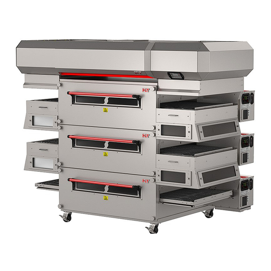
XLT Electric Oven & XLT Hood
Installation & Operation Manual
Read This Manual Before Using This Appliance.
CAUTION
Current versions of this manual, Technical/Rough-In Specifications, Parts and Service Manual, Fire Suppression In-
stallation, Architectural Drawings, and a list of International Authorized Distributors are available at:
For use with the following XLT Electric Oven Versions:
Standard (S)
H
World (W)
H
Original Instructions
US: 888-443-2751 FAX: 316-943-2769
www.xltovens.com
For use with the following XLT Electric Hood Versions:
Standard (S)
World (W)
2000887
XLT Ovens
PO Box 9090
Wichita, Kansas 67277
INTL: +1-316-943-2751
SWH03HF02
F
F
WEB:
www.xltovens.com
XD 9005A
5/9/2023
Advertisement
Table of Contents

Related Manuals for XLT Ovens X3H-1832 Series


Summary of Contents for XLT Ovens X3H-1832 Series
- Page 1 For use with the following XLT Electric Oven Versions: For use with the following XLT Electric Hood Versions: Standard (S) Standard (S) World (W) World (W) 2000887 Original Instructions XLT Ovens PO Box 9090 Wichita, Kansas 67277 US: 888-443-2751 FAX: 316-943-2769 INTL: +1-316-943-2751 WEB: www.xltovens.com...
-
Page 2: Warning And Safety Information
WARNING AND SAFETY INFORMATION FOR YOUR SAFETY Do not store or use gasoline or other flammable vapors and liquids on the vi- cinity of this or any other appliance. WARNING Improper installation, adjustment, alteration, service or maintenance can cause property damage, injury, or death. Read the installation, operating and maintenance instructions thoroughly before installing or servicing this WARNING equipment. -
Page 3: Definitions And Symbols
WARNING AND SAFETY INFORMATION Definitions and Symbols A safety instruction (message) includes a “Safety Alert Symbol” and a signal word or phrase such as DANGER, WARNING or CAUTION. Each signal word has the following mean- ing: ISO 7000-0434: This symbol indicates a potentially hazardous situation that, if not avoided, can result in serious injury or death. - Page 4 Appliance is not to be cleaned with water jet (high pressure water). Most XLT ovens are certified for use in stacks of up to four (4) units of XLT products. Inte- gration of other manufacturer’s products into an oven stack is not recommended, and voids any warranties.
-
Page 5: Table Of Contents
TABLE OF CONTENTS Warning and Safety Information ......................2 Table of Contents ..........................5 Warranty ............................. 6 General ............................... 8 Receiving and Inspection ........................9 Installation Responsibilities ......................10 Oven Description ..........................11 Oven Crate Dimensions........................13 Oven Dimensions and Weights ......................14 Oven Requirements .......................... -
Page 6: Warranty
Warranty – US and Canada Rev J Approval Date: 09/22/2022 XLT warrants ovens manufactured after September 22, 2022 to be free from any defect in ma- terial and workmanship under normal use for seven (7) years from the date of original purchase by the end user, and further warrants main fan blades, conveyor shafts, and conveyor bearings for ten (10) years. -
Page 7: Warranty - International
Warranty – International Rev L Approval Date: 09/22/2022 XLT warrants ovens manufactured after September 22, 2022 to be free from any defect in material and workmanship under normal use for five (5) years from the date of original purchase by the end user, and further warrants main fan blades, conveyor shafts, and conveyor bearings for ten (10) years. -
Page 8: General
GENERAL Save This Manual This document is the property of the owner of this equipment. XLT reserves the right to make changes in design and specifications, and/or make additions to or improvements to its product without imposing any obligations upon itself to install them in products previously manufactured. -
Page 9: Receiving And Inspection
RECEIVING AND INSPECTION Notify Carrier of Damage at Once Upon receiving of all goods shipped by a Common Carrier, check for any exterior damage that may indicate interior damage. If conditions permit, open all crates and do a full inspection for any damage while the delivery driver is still there. -
Page 10: Installation Responsibilities
INSTALLATION RESPONSIBILITIES Owner/ Responsibility Service Company Contractor Site Survey: Verify electric and gas meter/regulator sizes Supply wiring from TS1 #R3, R4, R5 to exhaust fan Assembly of new hood per XLT Installation & Operation Manual Suspend XLT Hood from ceiling Weld ducting to XLT Hood Install new exhaust fan on roof Supply power to XLT Hood... -
Page 11: Oven Description
OVEN DESCRIPTION This manual covers the following XLT Oven and Hood models: Ovens Hood/Shroud Package Hood Size Shroud Size X3H-1832-xxxxx 02-9F-1832-xxxxx 1832 1832 X3H-2336-xxxxx 02-9F-2336-xxxxx 2440 2336 X3H-2440-xxxxx 02-9F-2440-xxxxx 2440 2440 X3H-3240-xxxxx 02-9F-3240-xxxxx 3240 3240 X3H-3250-xxxxx-DS 02-9F-3250-xxxxx 3255 3250DS X3H-3255-xxxxx 02-9F-3255-xxxxx 3255 3255... - Page 12 OVEN DESCRIPTION Sandwich Door Oven Lid Conveyor Flap Conveyor Control Box Crumb Tray Front Panel Knob Front Panel Product Stop Locking Swivel Caster Data Plate Control Box Lid Circuit Breaker Box Oven Control Large User Interface Control Panel Chain Guard Manual Drawer Technical Support INTL: +1-316-943-2751 Technical Support US: 888-443-2751...
-
Page 13: Oven Crate Dimensions
OVEN CRATE DIMENSIONS Domestic Wood Crate Pallets Domestic Wood Crate Dimensions Electric Oven Oven Model Z (With Oven) 85 5/8 31 5/8 17 1/4 59 3/4 1832 [2175] [803] [438] [1518] 85 5/8 31 5/8 17 1/4 63 1/2 2336 [2175] [803] [438]... -
Page 14: Oven Dimensions And Weights
OVEN DIMENSIONS AND WEIGHTS Single Stack CRATED WEIGHTS SINGLE OVEN SINGLE DOM. WOOD INTL. WOOD METAL SKID OVEN WEIGHT OVEN 47 5/6 70 1/4 67 1/4 1832 1832 [457] [813] [1215] [1784] [1708] [1092] [813] [258] [347] [364] [312] 70 1/4 65 3/4 2336 2336... - Page 15 OVEN DIMENSIONS AND WEIGHTS Double Stack CRATED WEIGHTS OVEN DOUBLE DOUBLE WEIGHT DOM. WOOD INTL. WOOD METAL SKID STACK OVEN 47 5/6 70 1/4 67 1/4 1030 1413 1488 1259 1832 1832 [457] [813] [1215] [1784] [1708] [1600] [813] [1321] [508] [467] [641]...
- Page 16 OVEN DIMENSIONS AND WEIGHTS Triple Stack OVEN CRATED WEIGHTS TRIPLE TRIPLE WEIGHT DOM. WOOD INTL. WOOD METAL SKID STACK OVEN 47 5/6 70 1/4 67 1/4 1457 2022 2134 1791 1832 1832 [457] [813] [1215] [1784] [1708] [1727] [432] [940] [1448] [508] [661]...
-
Page 17: Oven Requirements
OVEN REQUIREMENTS Electric Oven Electrical Requirements Per EACH Oven STANDARD WORLD Oven Model Volts AC Amps Hertz Phase KW Volts AC Amps Hertz Phase 1832 2336 2440 3240 3250-DS 3255 3855 4455 4 Wire Service - L1, L2, L3 5 Wire Service - L1, L2, L3 +1 Ground (per oven) N +2 Grounds (per oven) FOR EACH OVEN:... -
Page 18: Oven Only Rough-In Specifications
OVEN ONLY ROUGH-IN SPECIFICATIONS 1832, 2336 and 2440 Models These ovens are suitable for installation on either combustible or non-combustible floors, and adjacent to either combustible or non-combustible walls. The motor cover is designed to pro- vide the proper clearance to the back of the oven. The minimum side clearances are 6in./150mm, measured from the ends of the conveyor. - Page 19 OVEN ONLY ROUGH-IN SPECIFICATIONS Disconnect Switch Breaker Panel (Shown for reference only) Utilities must be easily accessible when the ovens are in the installed position. Do not install utilities behind the ovens. CAUTION All installations must conform to local building and mechanical codes. It is re- quired that the ovens be placed under a ventilation hood to provide exhaust ventila- NOTE tion and adequate air supply.
-
Page 20: Oven Assembly
OVEN ASSEMBLY Warning & Safety Information XLT ovens can easily be moved and stacked with the proper lifting equipment. The use of XLT approved lifting equipment is highly recommended. Contact XLT for more information. These ovens are heavy and can tip or fall causing bodily injury. - Page 21 OVEN ASSEMBLY Base Assembly - Single and Double Stack Base Assembly - Triple Stack Technical Support US: 888-443-2751 Technical Support INTL: +1-316-943-2751...
- Page 22 OVEN ASSEMBLY Review and understand the next eight (8) steps first. They illustrate how to stack the ovens safely. The Lifting Pipe hole, marked for the appropriate oven size, must be installed closest to the control box. If your lifting plates do not have all of our available sizes NOTE listed follow the table below.
- Page 23 OVEN ASSEMBLY The folding leg of the tripod must be positioned outward from the oven. NOTE Technical Support US: 888-443-2751 Technical Support INTL: +1-316-943-2751...
-
Page 24: Stacking The Ovens
OVEN ASSEMBLY Use the release tab on the strap to loosen and remove both straps. NOTE Stacking the Ovens Failure to engage the Lifting Jacks into the Lifting Pipe properly and completely will result in damage, injury, or death from a falling oven. DANGER Both jacks should be raised in unison, otherwise they may bind and a dangerous ... - Page 25 OVEN ASSEMBLY Individuals with pacemakers or internal medical devices should not handle strong rare-earth magnets. These magnets are found in the sandwich door assembly. WARNING Removing Finger Clips All DS model front panels will have lifting handles. NOTE Finger clips for transportation purposes only. Discard once removed. NOTE Installing Sandwich Door Technical Support US: 888-443-2751...
- Page 26 OVEN ASSEMBLY Installing Accessories Conveyor Flap Control Box Plate Technical Support INTL: +1-316-943-2751 Technical Support US: 888-443-2751...
-
Page 27: Oven Connection
OVEN CONNECTION Physical Location and Spacing Requirements These ovens are suitable for installation on either combustible or non-combustible floors, and adjacent to either combustible or non-combustible walls. The motor cover is designed to pro- vide the proper clearance to the back of the oven. The minimum side clearances are 6in. / 150mm, measured from the end of the conveyor. -
Page 28: Oven Fire Suppression
The kit does not interfere with any operations or maintenance. For detailed information regarding fire suppression, see manual XD-9011 Fire Suppression Installation for XLT Hoods and XLT Ovens. Technical Support INTL: +1-316-943-2751 Technical Support US: 888-443-2751... - Page 29 OVEN FIRE SUPPRESSION Technical Support US: 888-443-2751 Technical Support INTL: +1-316-943-2751...
-
Page 30: Oven Ventilation Guidelines
Requirements vary throughout the country depending upon location. Proper ventilation is the oven owner’s responsibility. The XLT hood system is designed to meet all requirements for XLT ovens and it is our recommendation that this system be used. -
Page 31: Oven Initial Start-Up
Complete Start-up checklist with owner signature and return to XLT. Do Not Exceed 65 Hz On VFD Settings. CAUTION All XLT ovens will come programmed for a bake time of 5:00 minutes and a tem- perature of 500°F/260°C. End users are responsible for determining oven settings. NOTE The tables below indicate minimum and maximum values for bake time and tem- perature. -
Page 32: Oven Operation
OVEN OPERATION This oven is not capable of being safely placed in operation in the event of a power failure. No attempt should be made to operate this oven during power failure. CAUTION Power Up Arrow XLT Logo Down Arrow Temperature Belt Speed Menu... -
Page 33: Oven Operator Controls
OVEN OPERATOR CONTROLS Menu Mode (Optional) The Menu programming can store up to twelve (12) preset menus that can be recalled by number as needed. Each program contains a specified baking temperature and belt time. To Select A Menu Program 1. - Page 34 OVEN OPERATOR CONTROLS Oven Machine Control LED’s Status: Oven Machine Control Power Green Steady: Oven has power. Conveyor Green Steady: Conveyors are active. Flash: Problem is detected. Heat Green Steady: Oven is calling for heat. Will re- main lit while climbing to temperature. Flash: Problem is detected.
- Page 35 OVEN OPERATOR CONTROLS Split Belt Conveyor Time Controls Front Conveyor Belt Back Conveyor Belt To maintain optimal bake, new fingers may be needed if belt direction is changed. NOTE If Standard belt, only one (1) conveyor time will be displayed (refer to image below).
-
Page 36: Oven Cleaning
OVEN CLEANING Your XLT oven is constructed of stainless steel. Most commercial cleaning agents may be used safely on all stainless steel surfaces. Check application restrictions on product label prior to usage. Observe recommended precautionary and safety measures as dictated by the product manu- facturer. - Page 37 OVEN CLEANING Oven must be cool and the electric cord unplugged before any cleaning or maintenance is done. DANGER If the oven is to be removed from its installed location for cleaning or servicing, the following procedure is to be followed: CAUTION 1.
- Page 38 OVEN CLEANING Opening the Sandwich Door will provide a grip location for removing the Front Panel. Front Panels can weigh up to 66 lbs. [30 kg]. Use caution when lifting. CAUTION Individuals with pacemakers or internal medical devices should not handle strong rare-earth magnets.
- Page 39 OVEN CLEANING Technical Support US: 888-443-2751 Technical Support INTL: +1-316-943-2751...
- Page 40 OVEN CLEANING DO NOT spray liquid cleaning agents in the slots and holes in the rear of control box, underneath the control box, or the main fan motor cover. CAUTION Technical Support INTL: +1-316-943-2751 Technical Support US: 888-443-2751...
-
Page 41: Oven Maintenance
OVEN MAINTENANCE As with any appliance, periodic maintenance is required. Many factors affect this schedule such as product mix and hours of usage. An example schedule is included. Oven must be cool and the electric cord unplugged before any cleaning or mainte- nance is performed. -
Page 42: Oven Troubleshooting
Quantity of toppings XLT ovens can be configured to cook a wide variety of food items. This is accomplished by designing a finger group to control the baking characteristics. Generally speaking, most cook- ing is a “bottom up” process. The hot air from the bottom row of fingers has to go through the conveyor (a distance of about 2”... -
Page 43: Mechanical Function
OVEN TROUBLESHOOTING Mechanical Function If your oven does not function properly, please verify the following conditions: 1. Verify that the power cord to the oven is connected and/or plugged in if equipped with a plug and receptacle. 2. Check all circuit breakers on the oven control panel and on the back of the control box to en- sure they have not been tripped. - Page 44 OVEN TROUBLESHOOTING LUI Service Error Codes Display Alarm MC LED Error Determination Troubleshooting Alarm LED on. Flash HEAT Temp Sensor Error, Open or Short. Perform A Hard Reset. If Error Still Exists, Oven Probe LED. All other LED's operate Temp <40F (4C) or >700F (371C) Contact XLT.
-
Page 45: Hood Installation
HOOD INSTALLATION Check all local codes prior to installation. Special requirements may be necessary depending upon building material construction. It is the installing contractor’s re- sponsibility to ensure that the structure the hood is to be hung from the ceiling, DANGER meets all codes, and can support the hood weight. -
Page 46: Hood Description
All XLT hoods are available with optional pre-piped for fire suppression, allowing for simple, in-field installations. For fire suppression detailed information see manual XD-9011 Fire Suppression Installation for XLT Hoods and XLT Ovens. The XLT hood was designed to conform to the requirements of IMC 2015 or current version, which is a Type I hood. -
Page 47: Hood And Shroud Crate Dimensions
HOOD AND SHROUD CRATE DIMENSIONS Hood/Shroud Package Ovens Hood/Shroud Package Hood Size Shroud Size X3H-1832-xxxxx 02-9F-1832-xxxxx 1832 1832 X3H-2336-xxxxx 02-9F-2336-xxxxx 2440 2336 X3H-2440-xxxxx 02-9F-2440-xxxxx 2440 2440 X3H-3240-xxxxx 02-9F-3240-xxxxx 3240 3240 X3H-3250-xxxxx-DS 02-9F-3250-xxxxx 3255 3250DS X3H-3255-xxxxx 02-9F-3255-xxxxx 3255 3255 X3H-3855-xxxxx 02-9F-3855-xxxxx 3855 3855 X3H-4455-xxxxx... - Page 48 HOOD AND SHROUD CRATE DIMENSIONS International Hood Crates Hood Crate Dimensions Oven (With Model Hood) 29 1/2 65 3/4 1832 [2667] [749] [1668] 29 1/2 65 3/4 2336 [2667] [749] [1668] 29 1/2 65 3/4 2440 [2667] [749] [1668] 29 1/2 65 3/4 3240 [2667]...
-
Page 49: Hood Dimensions And Weights
HOOD DIMENSIONS AND WEIGHTS All dimensions are from finished floor Oven Hood Dimensions Hood Only Hood & Shroud Weights Crated Weight Domestic Crated Weight Model Weights Double Triple Hood Double Triple Hood Double Triple 33 1/2 85 1/4 21 1/2 30 1/4 1832 [851]... -
Page 50: Recommended Exhaust Flow Rates
RECOMMENDED EXHAUST FLOW RATES Exhaust Flow Rates VOLUME (min. recommended) Ovens On 18xx 24xx 32xx 38xx 44xx Top Middle Bottom Single [14.16] [14.16] [14.16] [14.16] [14.16] [14.16] [14.16] [14.16] [14.16] [14.16] Double [14.16] [14.16] [18.97] [22.65] [26.9] [14.16] [14.16] [18.97] [22.65] [26.9] [14.16]... - Page 51 RECOMMENDED EXHAUST FLOW RATES Exhaust Flow Rates VELOCITY (min. recommended) Ovens On 18xx 24xx 32xx 38xx 44xx Top Middle Bottom 187.5 187.5 93.75 93.75 93.75 Single [57.15] [57.15] [28.58] [28.58] [28.58] 187.5 187.5 93.75 93.75 93.75 [57.15] [57.15] [28.58] [28.58] [28.58] 187.5 187.5...
-
Page 52: Hood Electrical Requirements
HOOD ELECTRICAL REQUIREMENTS Inputs into Electrical XLT Hood Electric Utility Specifications # of Circuits Rating Purpose 208/240 VAC, 1 Phase, 60 Hz, 6 Amp VFD Controller Standard up to 3 120 VAC, 1 Phase, 60 Hz, 20 Amp Ovens 230 VAC, 1 Phase, 50 Hz, 6 Amp VFD Controller World up to 3... -
Page 53: Hood Rough-In Specifications
HOOD ROUGH-IN SPECIFICATIONS *The above image shown is a Gas Oven Configuration All structural members, electrical and fire suppression equipment shown for reference only. Technical Support US: 888-443-2751 Technical Support INTL: +1-316-943-2751... -
Page 54: Hood Electrical Connections
HOOD ELECTRICAL CONNECTIONS VFD Control Box Ground Bar Terminal Strips (TS) Hood Machine Control (HMC) Power Supply (PS) VFD Controller (VFD) Circuit Breakers (CB) Prop Rod Hood User Interface (HUI) VFD Control Box (Cover removed) Technical Support INTL: +1-316-943-2751 Technical Support US: 888-443-2751... - Page 55 HOOD ELECTRICAL CONNECTIONS Input Power to VFD Controller - Standard (208/240V Single Phase) Technical Support US: 888-443-2751 Technical Support INTL: +1-316-943-2751...
- Page 56 HOOD ELECTRICAL CONNECTIONS Input Power to VFD Controller - World (230V / 50Hz) Technical Support INTL: +1-316-943-2751 Technical Support US: 888-443-2751...
- Page 57 HOOD ELECTRICAL CONNECTIONS Output Power from VFD to Exhaust Fan - Standard Technical Support US: 888-443-2751 Technical Support INTL: +1-316-943-2751...
- Page 58 HOOD ELECTRICAL CONNECTIONS Output Power from VFD to Exhaust Fan - World Technical Support INTL: +1-316-943-2751 Technical Support US: 888-443-2751...
- Page 59 HOOD ELECTRICAL CONNECTIONS MUA Unit Relay Customer Supplied Power Power Neutral Supply from Breaker Panel 7 Amperes Maximum TS 1 TS 2 Some wiring removed for clarity. See schematic for details. NOTE Technical Support US: 888-443-2751 Technical Support INTL: +1-316-943-2751...
- Page 60 HOOD ELECTRICAL CONNECTIONS MUA Unit Relay MUA Unit Relay MUA Unit Relay Customer Supplied Customer Supplied Customer Supplied Power Power Power Power Power Power Neutral Supply from Breaker Panel 7 Amperes Maximum TS 1 TS 2 Some wiring removed for clarity. See schematic for details.
- Page 61 HOOD ELECTRICAL CONNECTIONS Air Proving Switch Air Proving Switch Exhaust This is a grounding circuit. Do not use line voltage. CAUTION Must Remove (3) Jumpers TS 1 TS 2 Some wiring removed for clarity. See schematic for details. NOTE Technical Support US: 888-443-2751 Technical Support INTL: +1-316-943-2751...
- Page 62 HOOD ELECTRICAL CONNECTIONS Fire Alarm Relay - Voltage and Frequency Connect wires from the Junction Box to the Normally Open (NO) contacts in the Fire Suppression cabinet. NOTE TS1-10R will have voltage when the Fire Suppression system has been activated. NOTE Technical Support INTL: +1-316-943-2751 Technical Support US: 888-443-2751...
-
Page 63: Hood And Shroud Assembly
HOOD AND SHROUD ASSEMBLY Oven must be cool and the electric cord unplugged before hood assembly begins. DANGER If the oven is to be removed from its installed location for hood assembly and in- stallation, the following procedure is to be followed: CAUTION 1. - Page 64 HOOD AND SHROUD ASSEMBLY Prepare Hood - Install Hood Transition Rails Technical Support INTL: +1-316-943-2751 Technical Support US: 888-443-2751...
- Page 65 HOOD AND SHROUD ASSEMBLY Lifting Gear Setup All 44xx hood models will work in the same slot as 38xx hood models when utiliz- ing the current lifting equipment. Hooks will not be seated clear to either box end NOTE edge. Technical Support US: 888-443-2751 Technical Support INTL: +1-316-943-2751...
- Page 66 HOOD AND SHROUD ASSEMBLY Warning and Safety Information An XLT hood can easily be moved with the proper lifting equipment. The use of XLT ap- proved lifting equipment is highly recommended. Contact XLT for more information. These hood is heavy and can tip or fall causing bodily injury. ...
- Page 67 HOOD AND SHROUD ASSEMBLY Lifting Jack Setup The folding leg of the tripod must be positioned outwards from the hood. NOTE Technical Support US: 888-443-2751 Technical Support INTL: +1-316-943-2751...
- Page 68 HOOD AND SHROUD ASSEMBLY Stacking Hood on the Ovens Both jacks should be raised in unison, otherwise they may bind and a dangerous situation will develop. Do not put any part of yourself under the hood at any time. ...
- Page 69 HOOD AND SHROUD ASSEMBLY Hang Hood From Ceiling Joists Hood Must Be Suspended From Ceiling Joists. DANGER All thread provided by others 69 5/8 ± 1/8 [1768] This measurement is from the finished floor to the bottom of the suspended hood. NOTE: All dimensions in inches [millimeters], ±...
- Page 70 HOOD AND SHROUD ASSEMBLY Install Grease Trays, Covers, and Grease Filters Filter Block Off to be Grease Filters over Grease Tray Grease Tray Technical Support INTL: +1-316-943-2751 Technical Support US: 888-443-2751...
- Page 71 HOOD AND SHROUD ASSEMBLY F Hood Shroud Work Instruction Scan To Watch The Video Instruction Or Visit: Or Visit: xltovens.com/f2-shrouds xltovens.com/f2-shrouds Tool Requirements Screwdriver: Phillips #2 3/8” (10mm) Wrench Shroud Boxes Double Stack Triple Stack Box Labels RH Upper Shroud Box LH Upper Shroud Box RH Lower Shroud Box LH Lower Shroud Box...
-
Page 72: Hood Connection
Install Hood Relocation Cord Assembly All hoods are outfitted with three (3) switch relocation receptacles, regardless of how many XLT ovens are installed. For a single oven use “Top” location. For a double stack use “Top” location for upper oven and “Bottom”... - Page 73 HOOD CONNECTION Connect Hood Relocation Cord Assembly Technical Support US: 888-443-2751 Technical Support INTL: +1-316-943-2751...
- Page 74 This page is intentionally left blank. Technical Support INTL: +1-316-943-2751 Technical Support US: 888-443-2751...
-
Page 75: Hood Initial Start-Up
HOOD INITIAL START-UP Variable Frequency Drive Adjustments All XLT Hoods are functionally tested at the factory. Operation is verified, and adjust- ments are made to ensure proper operation. However, field conditions are sometimes different than factory conditions. It is necessary to have an authorized service technician verify operation and make field adjustments if needed. -
Page 76: Hood Operator Controls
(LIGHTS) Error Information Oven Buttons When XLT ovens are outfitted with an XLT hood and the receptacles are plugged into the hood instead of the wall, the main power button of the oven is disabled and NOTE no longer operates. The Hood User Interface (HUI) on the XLT hood overrides the oven power button. -
Page 77: Hood Valance Kit
HOOD VALANCE KIT The optional valance kit size is determined by XLT hood size and distance from the fin- ished floor to the installed drop ceiling height. The valance kit screws directly to the XLT hood and does not require any structural support. The plastic coating must be removed from all parts prior to installation. - Page 78 HOOD VALANCE KIT Install Valance Brackets Install Front and Back Panels Technical Support INTL: +1-316-943-2751 Technical Support US: 888-443-2751...
- Page 79 HOOD VALANCE KIT Install Corner Panels Install End Panels Technical Support US: 888-443-2751 Technical Support INTL: +1-316-943-2751...
-
Page 80: Hood Duct Wrap Kit
HOOD DUCT WRAP KIT Optional Hood Duct Wrap Install Duct Wrap Brackets Install Duct Wrap Panels Technical Support INTL: +1-316-943-2751 Technical Support US: 888-443-2751... -
Page 81: Hood Cleaning
HOOD CLEANING As with any appliance, periodic maintenance is required. Many factors affect this schedule such as product mix and hours of usage. An example schedule is included. Your XLT hood is constructed of stainless and aluminized steel. Check application re- strictions on product label prior to usage. - Page 82 HOOD CLEANING Remove fastener from back of upper shroud, Remove the upper shrouds from both sides on both sides of the hood. of the hood. Remove the grease filters from both sides Remove the grease tray from both sides of the hood. Refer to the page of hood and of the hood.
- Page 83 This page is intentionally left blank. Technical Support US: 888-443-2751 Technical Support INTL: +1-316-943-2751...
-
Page 84: Oven Electrical Schematics
OVEN SCHEMATIC STANDARD 208/240 VAC LH Technical Support INTL: +1-316-943-2751 Technical Support US: 888-443-2751... - Page 85 OVEN SCHEMATIC STANDARD 208/240 VAC RH Technical Support US: 888-443-2751 Technical Support INTL: +1-316-943-2751...
- Page 86 OVEN SCHEMATIC STANDARD 208/240 VAC LH Technical Support INTL: +1-316-943-2751 Technical Support US: 888-443-2751...
- Page 87 OVEN SCHEMATIC STANDARD 208/240 VAC RH Technical Support US: 888-443-2751 Technical Support INTL: +1-316-943-2751...
- Page 88 OVEN SCHEMATIC STANDARD 208/240 VAC LH Technical Support INTL: +1-316-943-2751 Technical Support US: 888-443-2751...
- Page 89 OVEN SCHEMATIC STANDARD 208/240 VAC RH Technical Support US: 888-443-2751 Technical Support INTL: +1-316-943-2751...
- Page 90 OVEN SCHEMATIC WORLD 380/415 VAC LH Technical Support INTL: +1-316-943-2751 Technical Support US: 888-443-2751...
- Page 91 OVEN SCHEMATIC WORLD 380/415 VAC RH Technical Support US: 888-443-2751 Technical Support INTL: +1-316-943-2751...
- Page 92 OVEN SCHEMATIC WORLD 380/415 VAC LH Technical Support INTL: +1-316-943-2751 Technical Support US: 888-443-2751...
- Page 93 OVEN SCHEMATIC WORLD 380/415 VAC RH Technical Support US: 888-443-2751 Technical Support INTL: +1-316-943-2751...
- Page 94 OVEN SCHEMATIC WORLD 380/415 VAC LH Technical Support INTL: +1-316-943-2751 Technical Support US: 888-443-2751...
- Page 95 OVEN SCHEMATIC WORLD 380/415 VAC RH Technical Support US: 888-443-2751 Technical Support INTL: +1-316-943-2751...
- Page 96 OVEN SCHEMATIC WORLD NON VFD 380/415 VAC LH Technical Support INTL: +1-316-943-2751 Technical Support US: 888-443-2751...
- Page 97 OVEN SCHEMATIC WORLD NON VFD 380/415 VAC RH Technical Support US: 888-443-2751 Technical Support INTL: +1-316-943-2751...
- Page 98 OVEN SCHEMATIC WORLD NON VFD 380/415 VAC LH Technical Support INTL: +1-316-943-2751 Technical Support US: 888-443-2751...
- Page 99 OVEN SCHEMATIC WORLD NON VFD 380/415 VAC RH Technical Support US: 888-443-2751 Technical Support INTL: +1-316-943-2751...
- Page 100 OVEN SCHEMATIC WORLD NON VFD 380/415 VAC LH Technical Support INTL: +1-316-943-2751 Technical Support US: 888-443-2751...
- Page 101 OVEN SCHEMATIC WORLD NON VFD 380/415 VAC RH Technical Support US: 888-443-2751 Technical Support INTL: +1-316-943-2751...
-
Page 102: Hood Electrical Schematics
HOOD SCHEMATIC - STANDARD W/FS-W/VFD Technical Support INTL: +1-316-943-2751 Technical Support US: 888-443-2751... - Page 103 HOOD SCHEMATIC - WORLD W/FS-W/VFD Technical Support US: 888-443-2751 Technical Support INTL: +1-316-943-2751...
- Page 104 HOOD SCHEMATIC - ELECTRIC W/FS-W/VFD Technical Support INTL: +1-316-943-2751 Technical Support US: 888-443-2751...
- Page 105 HOOD SCHEMATIC W/O FS-W/O VFD Technical Support US: 888-443-2751 Technical Support INTL: +1-316-943-2751...
-
Page 106: Certifications
6. EN 61000-6-3:2007 +A1:2011 EMC Immunity for residential, commercial & light in- dustrial ¹ The noted certifications for XLT ovens and XLT Hood are performed and documented by Intertek Testing Services NA Inc. 165 Main Street, Cortland, NY 13045. Intertek is a nationally and internationally certified testing and accreditation agency. - Page 107 3. ULC-S646, Standard for Exhaust Hoods and Related Controls for Commercial and Insti- tutional Kitchens ¹ The noted certifications for XLT ovens and XLT Hood are performed and documented by Intertek Testing Services NA Inc. 165 Main Street, Cortland, NY 13045.
-
Page 108: Typical Store Installation
TYPICAL STORE INSTALLATION Fan Curb Exhaust Fan Roof Top Unit (RTU) Roof 1/2” All-Thread Supported by Unistrut (2 Locations) Ceiling Joist Drop Ceiling Duct Wrapper (Optional) Electrical Service Panel Gas Manifold Gas Hose *The above image shown is a Gas Oven Configuration Welded Duct Fire Suppression Service Panel... -
Page 109: Start-Up Checklist
Oven Initial Start-up Checklist - Remove and Return to XLT Ovens Fill out all information and print legibly Start-Up Information Customer Name:_____________________________________ Company Name: _____________________________________ Phone #: ___________________________________________ Email: _____________________________________________ Address:________________________________________________________________________________________________ City: _______________________________ State: _____________ Zip: ___________ Country:_________________ Follow Requirements outlined in Installation and... -
Page 110: Notes
NOTES Technical Support INTL: +1-316-943-2751 Technical Support US: 888-443-2751...
Need help?
Do you have a question about the X3H-1832 Series and is the answer not in the manual?
Questions and answers