Table of Contents
Advertisement
Quick Links
XLT Gas Oven & AVI Hood
Installation & Operation Manual
This appliance is for professional use by qualified personnel. This appliance must be in-
stalled by qualified persons in accordance with the regulations in force. This appliance must be in-
stalled with sufficient ventilation to prevent the occurrence of unacceptable concentrations of sub-
stances harmful to health in the room in which it is installed. This appliance needs an unobstructed
flow of fresh air for satisfactory operation & must be installed in a suitably ventilated room in accor-
CAUTION
dance with current regulations. This appliance should be serviced by qualified personnel at least
every 12 months or sooner if heavy use is expected.
Current versions of this manual, Technical/Rough-In Specifications, Parts & Service Manual, Architectural
Drawings, & a list of International Authorized Distributors are available at:
For use with the following XLT Gas Oven Versions:
Australia (AE)
F3
Korea (K)
F3
Standard (S)
F3
World (W)
F3
US: 888-443-2751 FAX: 316-943-2769
For use with the following AVI Gas Hood Versions:
Standard (S)
World (W)
GAS40066
SAI Global
2000887
XLT Ovens
PO Box 9090
Wichita, Kansas 67277
INTL: 316-943-2751
XD 9004J
AF3KF3SWF3HE
05/09/2017
www.xltovens.com
E
E
WEB:
www.xltovens.com
Advertisement
Table of Contents

Related Manuals for XLT Ovens X3F3-1832 Series


Summary of Contents for XLT Ovens X3F3-1832 Series
- Page 1 For use with the following AVI Gas Hood Versions: Australia (AE) Standard (S) Korea (K) World (W) Standard (S) World (W) GAS40066 SAI Global 2000887 XLT Ovens PO Box 9090 Wichita, Kansas 67277 US: 888-443-2751 FAX: 316-943-2769 INTL: 316-943-2751 WEB: www.xltovens.com...
-
Page 2: Warning & Safety Information
Appliance is not to be cleaned with high pressure water. XLT ovens are certified for use in stacks of up to three (3) units of XLT products. Integration of other manufacturer’s products into an oven stack is not recommended, & voids any warran- ties. - Page 3 WARNING & SAFETY INFORMATION Definitions & Symbols A safety instruction (message) includes a “Safety Alert Symbol” & a signal word or phrase such as DANGER, WARNING or CAUTION. Each signal word has the following meaning: Indicates a potentially hazardous situation that, if not avoided, can result in serious injury or death.
-
Page 4: Warranty
The gas, electric, and HVAC utilities must be connected to the oven and installed by locally licensed contractors Failure to contact XLT Ovens prior to contacting a repair company for warranty work voids any and all warranties WHAT IS NOT COVERED: ... - Page 5 Warranty – International Rev J Approval Date: 11/01/2016 When purchased through an Authorized International Distributor, XLT warrants Version F Ovens and Version E Hoods to be free from any defect in material and workmanship under normal use. The Authorized International Distributor will repair XLT products during the warranty period. This warranty is extended to the original end user purchaser and is not transferable without prior written consent of the Authorized International Distributor.
- Page 6 This page intentionally left blank. Technical Support US: 888-443-2751 Technical Support INTL: 316-943-2751...
-
Page 7: Installation Responsibilities
INSTALLATION RESPONSIBILITIES XLT/Service Owner/ Responsibility Company Contractor Site Survey: Verify electric and gas meter/regulator sizes Supply wiring from TS1 #R3, R4, R5 to exhaust fan Supply (1) single phase 230 volt 10 amp circuit from breaker panel to XLT Hood Assembly of new hood per XLT Installation &... - Page 8 24 hours may void the opportunity to have the claim re- solved. XLT Ovens wants you to be totally satisfied with every aspect of owning & using your oven & hood. Your feedback, both positive & negative, is very important to us as it helps us un- derstand how to improve our products &...
-
Page 9: Table Of Contents
TABLE OF CONTENTS Warning & Safety Information..................... 2 Warranty ............................4 Installation Responsibilities ......................7 Oven Description ........................10 Oven Crate Dimensions......................13 Oven Dimensions & Weights ..................... 14 Oven Requirements ........................16 Oven Only Rough-In Specifications ..................23 Oven Assembly .......................... 25 Oven Connection ........................ -
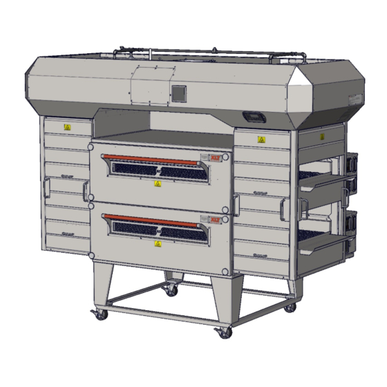
Page 10: Oven Description
XLT. In addition, moving equip- ment such as carts and lifting jacks are available to help install and move ovens. Please contact XLT Ovens or your Authorized Distributor for more information. Technical Support US: 888-443-2751... - Page 11 OVEN DESCRIPTION Sandwich Door Oven Lid Conveyor Control Box Crumb Tray Front Panel Knob Product Stop Front Panel Locking Swivel Caster Data Plate Control Box Lid Oven Control User Interface Control Panel Chain Guard Document Tray Technical Support US: 888-443-2751 Technical Support INTL: 316-943-2751...
- Page 12 This page is intentionally left blank. Technical Support US: 888-443-2751 Technical Support INTL: 316-943-2751...
-
Page 13: Oven Crate Dimensions
OVEN CRATE DIMENSIONS INTERNATIONAL WOOD CRATES International Wood Crate Dimensions Gas and Electric Ovens Oven Model 29 3/4 60 3/8 1832 [1930] [756] [1534] 29 3/4 66 3/8 2440 [2134] [756] [1686] 29 3/4 74 3/8 3240 [2134] [756] [1889] 29 3/4 74 3/8 3255... -
Page 14: Oven Dimensions & Weights
OVEN DIMENSIONS & WEIGHTS Technical Support US: 888-443-2751 Technical Support INTL: 316-943-2751... - Page 15 OVEN DIMENSIONS & WEIGHTS SINGLE OVEN CRATED OVEN WEIGHT WEIGHT 48 3/8 70 1/4 67 1/4 42 3/4 1832 [457] [813] [1229] [1784] [1708] [1086] [813] [276] [338] 54 3/8 78 1/4 75 1/4 42 3/4 2440 [610] [1016] [1381] [1988] [1911] [1086]...
-
Page 16: Oven Requirements
OVEN REQUIREMENTS GAS AND ELECTRICAL INLET DIMENSIONS WORLD & AUSTRALIA (230V / 50 Hz) Gas Connection Power Connection Technical Support US: 888-443-2751 Technical Support INTL: 316-943-2751... - Page 17 OVEN REQUIREMENTS SINGLE OVEN 18.25 9 1/2 25 1/2 1832 [464] [241] [648] 18.25 9 1/2 25 1/2 2440 [464] [241] [648] 18.25 9 1/2 25 1/2 3240 [464] [241] [648] 18.25 9 1/2 25 1/2 3255 [464] [241] [648] 18.25 9 1/2 25 1/2...
- Page 18 OVEN REQUIREMENTS All values shown on this page are per each oven Standard (120V/60Hz) - Gas Oven Heating Values & Orifice Sizes Australia (230V/50Hz) - Gas Oven Heating Values & Orifice Sizes Heating Values Orifice Sizes Heating Values Orifice Sizes Oven Model All Fuels Oven Model...
- Page 19 OVEN REQUIREMENTS Oven Gas Group Natural Gas Propane Gas Gas Group 3B/P (30) 3P (30/37/50) 3B (37) Inlet pressure (mbar) 20 20/25 25 28/30/37/50 28-30/37/50 30/37/50 (1) per burner Number of injectors Fixed Main burner opening size Electric Direct Spark Igniter Ignition BSP 3/4"...
- Page 20 OVEN REQUIREMENTS Gas Supply Requirements for All Ovens All installations must conform to local building & mechanical codes. NOTE 1. The gas supply shall have a gas meter & regulator large enough to handle ALL of the gas ap- pliances, such as the furnace, water heater, & ovens in operation at the same time. Add up all of the Btu/kw/MJ ratings to determine the total load.
- Page 21 OVEN REQUIREMENTS A minimum of a 1 1/2 supply line is required. Item # Description ¾ Manual Gas Valve 1-½ Ball Valve ¾ x 3 Nipple 1-½ Pipe Cap 1-½ x 10 Nipple 1-½ x 3 Nipple 1-½ x 5 Nipple 1-½...
- Page 22 OVEN REQUIREMENTS All values shown this page are per each oven Gas Oven Electrical Requirements Per EACH Oven Standard Australia & World Korea Oven Model Volts AC Amps Hertz Volts AC Amps Hertz Volts AC Watts 1832 2440 220/230/ 3240 50/60 50/60 3255...
-
Page 23: Oven Only Rough-In Specifications
OVEN ONLY ROUGH-IN SPECIFICATIONS These ovens are suitable for installation on either combustible or non-combustible floors, and adjacent to either combustible or non-combustible walls. The motor cover is designed to pro- vide the proper clearance to the back of the oven. The minimum side clearances are 6in. / 150mm, measured from the end of the conveyor. - Page 24 OVEN ONLY ROUGH-IN SPECIFICATIONS 3.00 [76] 6.00 Gas Manifold [152] Electrical Supply 48.00 [1219] 42.00 [1067] All installations must conform to local building and mechanical codes. It is required that the ovens be placed under a ventilation hood to provide exhaust ventilation and NOTE adequate air supply.
-
Page 25: Oven Assembly
OVEN ASSEMBLY Base Assembly - Single & Double Stack Base Assembly - Triple Stack Technical Support US: 888-443-2751 Technical Support INTL: 316-943-2751... - Page 26 OVEN ASSEMBLY WARNING & SAFETY INFORMATION XLT ovens can easily be moved and stacked with the proper lifting equipment. The use of XLT approved lifting equipment is highly recommended. Contact XLT for more information. These ovens are heavy & can tip or fall causing bodily injury.
- Page 27 OVEN ASSEMBLY The Lifting Pipe hole, marked for the appropriate oven size, must be installed closest to the control box. NOTE Technical Support US: 888-443-2751 Technical Support INTL: 316-943-2751...
- Page 28 OVEN ASSEMBLY Stacking the Ovens Failure to engage the Lifting Jacks into the Lifting Pipe properly and completely will result in damage, injury, or death from a falling oven. DANGER Both jacks should be raised in unison, otherwise they may bind and a dangerous ...
- Page 29 OVEN ASSEMBLY Stacking the Ovens Removing Finger Clips Finger clips for transportation purposes only. Discard once removed. NOTE Technical Support US: 888-443-2751 Technical Support INTL: 316-943-2751...
-
Page 30: Oven Connection
OVEN CONNECTION Physical Location & Spacing Requirements These ovens are suitable for installation on either combustible or non-combustible floors, and adjacent to either combustible or non-combustible walls. The motor cover is designed to pro- vide the proper clearance to the back of the oven. The minimum side clearances are 6in. / 150mm, measured from the end of the conveyor. -
Page 31: Oven Fire Suppression
The kit does not interfere with any operations or main- tenance. For detailed information regarding fire suppression, see manual XD-9011 Fire Suppression Installation for AVI Hoods and XLT Ovens. Technical Support US: 888-443-2751 Technical Support INTL: 316-943-2751... - Page 32 OVEN FIRE SUPPRESSION Technical Support US: 888-443-2751 Technical Support INTL: 316-943-2751...
-
Page 33: Oven Ventilation Guidelines
Requirements vary throughout the country depending upon location. Proper ventilation is the oven owner’s responsibility. The AVI Hood system is designed to meet all requirements for XLT ovens and it is our recommendation that this system be used. -
Page 34: Oven Initial Start-Up
The Oven Initial Start-Up Checklist, found at the end of this manual, must be completed (both sides) at time of installation, signed by the Customer and returned to XLT Ovens and the Au- thorized Distributor to initiate Warranty Policy. If the Start-Up Checklist is not filled out com- pletely and returned to XLT Ovens, then the warranty will not be honored. -
Page 35: Oven Operation
OVEN OPERATION This oven is not capable of being safely placed in operation in the event of a power failure. No attempt should be made to operate this oven during power failure. CAUTION Power Button Up/Down Arrows XLT Logo Enter Button Temperature Button Menu Button Belt Speed Button... -
Page 36: Oven Operator Controls
OVEN OPERATOR CONTROLS Read and understand steps first. Screens will auto exit if no activity is sensed. Factory Tech Mode To enter Factory Tech Mode press and hold the 2 arrow buttons for 10 seconds. Software Version MC & UI Software Version. Press Down arrow to go to next screen. Image For Reference Only - See XLT For Correct Version. - Page 37 OVEN OPERATOR CONTROLS Fuel Type Gas or Electric. Factory default is Gas. To Change press ENTER. Use Up/Down ar- rows and ENTER to accept and advance. Remote Hood Switch Factory default is NO. If there is a Remote Hood Switch installed, then press ENTER and NO flashes.
- Page 38 OVEN OPERATOR CONTROLS Menu Mode (Optional) Menu Operation 1. To enter Menu Mode press MENU. 2. The number in the lower right hand corner will begin flashing. 3. Scroll through the menus by pressing Up/Down arrows (Max of 12 preset menus). 4.
- Page 39 OVEN OPERATOR CONTROLS Split Belt Conveyor Time Controls Left Side Right Side Conveyor Belt Conveyor Belt Large User Interface Oven Control Circuit Breakers Fan & Filter Temperature Controls 3270 and 3870 Only Left Side Right Side Burner Burner Large User Interface Oven Control...
-
Page 40: Oven Cleaning
OVEN CLEANING Your XLT oven is constructed of stainless steel. Most commercial cleaning agents may be used safely on all stainless steel surfaces. Check application restrictions on product label prior to usage. Observe recommended precautionary and safety measures as dictated by the product manu- facturer. - Page 41 OVEN CLEANING Oven must be cool and the electric cord unplugged before any cleaning or maintenance is done. DANGER If the oven is to be removed from its installed location for cleaning or servicing, the following procedure is to be followed: CAUTION 1.
- Page 42 OVEN CLEANING Opening the Sandwich Door will provide a grip location for removing the Front Panel. Front Panels can weigh up to 75 lbs. [34 kg]. Use caution when lifting. CAUTION Technical Support US: 888-443-2751 Technical Support INTL: 316-943-2751...
- Page 43 OVEN CLEANING Technical Support US: 888-443-2751 Technical Support INTL: 316-943-2751...
- Page 44 OVEN CLEANING DO NOT spray liquid cleaning agents in the slots and holes in the following loca- tions: Rear of Control Box Underneath Control Box CAUTION Main Fan Motor Cover Technical Support US: 888-443-2751 Technical Support INTL: 316-943-2751...
-
Page 45: Oven Maintenance
OVEN MAINTENANCE As with any appliance, periodic maintenance is required. Many factors affect this schedule such as product mix and hours of usage. An example schedule is included. Oven Maintenance Schedule Semi- Daily Weekly Monthly Annual Cleaning Empty Crumb Trays □... -
Page 46: Oven Troubleshooting
Quantity of toppings XLT ovens can be configured to cook a wide variety of food items. This is accomplished by arranging the fingers to control the baking characteristics. Generally speaking, most cooking is a “bottom up” process. The hot air from the bottom row of fingers has to go through the conveyor (a distance of about 2”... - Page 47 OVEN TROUBLESHOOTING Mechanical Function If your oven does not function properly, please verify the following conditions: 1. Verify that the power cord to the oven is connected and/or plugged in if equipped with a plug and receptacle. 2. Check all circuit breakers on the oven control panel and on the back of the control box to en- sure they have not been tripped.
-
Page 48: Hood Installation
HOOD INSTALLATION Check all local codes prior to installation. Special requirements may be necessary depending upon building material construction. It is the installing contractor’s re- sponsibly to ensure that the structure the hood is to be hung from meets all codes DANGER and can carry the hood weight. -
Page 49: Hood Description
All AVI hoods are available pre-piped for fire suppression, allowing for simple, in-field installations. For fire suppression detailed information see manual XD-9011 Fire Suppression In- stallation for AVI Hoods and XLT Ovens. The AVI hood was designed to conform to the requirements of IMC 2015 or current ver- sion, which is a Type I hood. - Page 50 This page is intentionally left blank. Technical Support US: 888-443-2751 Technical Support INTL: 316-943-2751...
-
Page 51: Hood And Shroud Crate Dimensions
HOOD AND SHROUD CRATE DIMENSIONS HOOD CRATES Hood Crate Dimensions Oven Model 94 1/4 58 3/8 xx32 [2394] [686] [1483] 102 1/4 64 3/8 xx40 [2597] [686] [1635] 117 1/4 72 3/8 xx55 [2978] [686] [1838] 132 1/4 72 3/8 xx70 [3359] [686]... -
Page 52: Hood Dimensions & Weights
HOOD DIMENSIONS & WEIGHTS ALL DIMENSIONS ARE FROM FINISHED FLOOR Technical Support US: 888-443-2751 Technical Support INTL: 316-943-2751... - Page 53 HOOD DIMENSIONS & WEIGHTS Oven Hood Dimensions Hood Weights Crated Weight (2 Crates) Model Single Double Triple Hood Single Double Triple 34 3/8 88 5/8 30 5/8 1832 [873] [2251] [457] [813] [778] [230] [225] [225] [237] [141] [120] [138] 40 3/8 96 5/8 33 5/8...
-
Page 54: Recommended Exhaust Flow Rates
RECOMMENDED EXHAUST FLOW RATES Exhaust Flow Rates VOLUME (min. recommended) Switches On 18xx 24xx 32xx 38xx Top Middle Bottom Single [14.16] [14.16] [14.16] [14.16] [14.16] [14.16] [14.16] [14.16] Double [14.33] [18.24] [23.45] [27.35] [14.33] [18.24] [23.45] [27.35] [14.16] [14.16] [14.16] [14.16] [14.33] [18.24]... - Page 55 RECOMMENDED EXHAUST FLOW RATES Exhaust Flow Rates VELOCITY (min. recommended) Switches On 18xx 24xx 32xx 38xx Top Middle Bottom 187.5 187.5 93.75 93.75 Single [57.15] [57.15] [28.58] [28.58] 187.5 187.5 93.75 93.75 [57.15] [57.15] [28.58] [28.58] 189.75 241.5 155.25 181.125 Double [57.84] [73.61]...
-
Page 56: Hood Electrical Requirements
HOOD ELECTRICAL REQUIREMENTS Inputs into Electrical AVI Hood Electric Utility Specifications # of Circuits Rating Purpose 208/240 VAC, 1 Phase, 60 Hz, 6 Amp VFD Controller Standard up to 3 120 VAC, 1 Phase, 60 Hz, 20 Amp Ovens 230 VAC, 1 Phase, 50 Hz, 6 Amp VFD Controller World up to 3... -
Page 57: Hood Rough-In Specifications
HOOD ROUGH-IN SPECIFICATIONS All structural members, electrical & fire suppression equipment shown for reference only. Technical Support US: 888-443-2751 Technical Support INTL: 316-943-2751... -
Page 58: Hood Electrical Connections
HOOD ELECTRICAL CONNECTIONS VFD Control Box - Standard (120V / 60Hz) Conduit Junction Box Hood Machine Control (HMC) Terminal Strips (TS) Power Supply (PS) VFD Controller (VFD) Hood User Interface (HUI) Fire Suppression Relay (R1) Time Delay Relay (R2) Circuit Breaker (CB) Technical Support US: 888-443-2751 Technical Support INTL: 316-943-2751... - Page 59 HOOD ELECTRICAL CONNECTIONS Input Power to Lights Technical Support US: 888-443-2751 Technical Support INTL: 316-943-2751...
- Page 60 HOOD ELECTRICAL CONNECTIONS Input Power to Ovens - Standard (120V / 60Hz) Technical Support US: 888-443-2751 Technical Support INTL: 316-943-2751...
- Page 61 HOOD ELECTRICAL CONNECTIONS Input Power to Ovens - World (230V / 50Hz) Technical Support US: 888-443-2751 Technical Support INTL: 316-943-2751...
- Page 62 HOOD ELECTRICAL CONNECTIONS Input Power to VFD Controller - Standard (120V / 60Hz) Technical Support US: 888-443-2751 Technical Support INTL: 316-943-2751...
- Page 63 HOOD ELECTRICAL CONNECTIONS Input Power to VFD Controller - World (230V / 50Hz) Technical Support US: 888-443-2751 Technical Support INTL: 316-943-2751...
- Page 64 HOOD ELECTRICAL CONNECTIONS Output Power from VFD to Exhaust Fan - Standard (120V / 60Hz) Technical Support US: 888-443-2751 Technical Support INTL: 316-943-2751...
- Page 65 HOOD ELECTRICAL CONNECTIONS Output Power from VFD to Exhaust Fan - World (230V / 50Hz) Technical Support US: 888-443-2751 Technical Support INTL: 316-943-2751...
- Page 66 HOOD ELECTRICAL CONNECTIONS MUA Damper Relays - Single Output - Voltage & Frequency MUA Unit Relay Customer Supplied Power Power Neutral Supply from Breaker Panel 7 Amperes Maximum TS 1 TS 2 Some wiring removed for clarity. See schematic for details. Technical Support US: 888-443-2751 Technical Support INTL: 316-943-2751...
- Page 67 HOOD ELECTRICAL CONNECTIONS MUA Damper Relays - Multiple Output - Voltage & Frequency MUA Unit Relay MUA Unit Relay MUA Unit Relay Customer Supplied Customer Supplied Customer Supplied Power Power Power Power Power Power Neutral Supply from Breaker Panel 7 Amperes Maximum TS 1 TS 2 Some wiring removed for clarity.
- Page 68 HOOD ELECTRICAL CONNECTIONS World (230V / 50Hz)-W/Air Proving Switches Air Proving Switch Air Proving Switch Exhaust This is a grounding circuit. Do not use line voltage CAUTION Must Remove (3) Jumpers TS 1 TS 2 Some wiring removed for clarity. See schematic for details. Technical Support US: 888-443-2751 Technical Support INTL: 316-943-2751...
- Page 69 HOOD ELECTRICAL CONNECTIONS Fire Alarm Relay - Voltage & Frequency Connect wires from the Junction Box to the Normally Open (NO) contacts in the Fire Suppression cabinet. NOTE Technical Support US: 888-443-2751 Technical Support INTL: 316-943-2751...
-
Page 70: Hood Assembly
HOOD ASSEMBLY Prepare Ovens - Remove Lid Screws - Two (2) Only Prepare Ovens - Control Box Closeout Bracket Conveyors have been removed for clarity Technical Support US: 888-443-2751 Technical Support INTL: 316-943-2751... - Page 71 HOOD ASSEMBLY Prepare Ovens - Front Shroud Brackets Technical Support US: 888-443-2751 Technical Support INTL: 316-943-2751...
- Page 72 HOOD ASSEMBLY Prepare Ovens - Bottom Rail Bracket Prepare Ovens - Control Box Side Closeout Technical Support US: 888-443-2751 Technical Support INTL: 316-943-2751...
- Page 73 HOOD ASSEMBLY Prepare Ovens - Rear Shroud Brackets Technical Support US: 888-443-2751 Technical Support INTL: 316-943-2751...
- Page 74 HOOD ASSEMBLY Prepare Hood Technical Support US: 888-443-2751 Technical Support INTL: 316-943-2751...
- Page 75 HOOD ASSEMBLY Lifting Gear Setup AVI hoods can easily be moved and stacked with the proper lifting equipment. The use of XLT approved lifting equipment is highly recommended. Contact XLT for more information. Technical Support US: 888-443-2751 Technical Support INTL: 316-943-2751...
- Page 76 HOOD ASSEMBLY Lifting Jack Setup Inspect cable prior to each use. If cable is frayed or shows signs of excessive wear & tear, DO NOT USE until cable is replaced. Check for smooth operation. The cable should not be pinched & should pass ...
- Page 77 HOOD ASSEMBLY Stacking Hood on the Ovens Failure to engage the Lifting Jacks into the Lifting Pipe properly and completely will result in damage, injury, or death from a falling hood. DANGER Both jacks should be raised in unison, otherwise they may bind and a dangerous ...
- Page 78 HOOD ASSEMBLY Hang Hood From Ceiling Joists Hood Must Be Suspended From Ceiling Joists DANGER All thread provided by others 69 5/8 +/- 1/8 [1768 +/- 3 This measurement is from the finished floor to the bottom of the suspended hood. NOTE Technical Support US: 888-443-2751 Technical Support INTL: 316-943-2751...
- Page 79 HOOD ASSEMBLY Install Grease Trays, Light Bulbs & Covers, and Grease Filters Filter Block Off to be Grease Filters over Grease Tray Grease Tray Technical Support US: 888-443-2751 Technical Support INTL: 316-943-2751...
- Page 80 HOOD ASSEMBLY Install Shroud Hanging Brackets Parts Removed For Clarity Technical Support US: 888-443-2751 Technical Support INTL: 316-943-2751...
- Page 81 HOOD ASSEMBLY Install Corner Posts Technical Support US: 888-443-2751 Technical Support INTL: 316-943-2751...
- Page 82 HOOD ASSEMBLY Install Bottom Rails Technical Support US: 888-443-2751 Technical Support INTL: 316-943-2751...
- Page 83 HOOD ASSEMBLY Install Bottom Rails 16 1/4” [413] 20 3/4” [528] Technical Support US: 888-443-2751 Technical Support INTL: 316-943-2751...
- Page 84 HOOD ASSEMBLY Install Control Box Upper Closeout If installing a 70” model, the same will apply for the LH side of ovens. NOTE Technical Support US: 888-443-2751 Technical Support INTL: 316-943-2751...
- Page 85 HOOD ASSEMBLY Install Shroud Panels - Front and Ends Install Take-Off Trays Technical Support US: 888-443-2751 Technical Support INTL: 316-943-2751...
- Page 86 HOOD ASSEMBLY Install Back Shroud Panel If installing a 70” model, refer to page 74 NOTE Technical Support US: 888-443-2751 Technical Support INTL: 316-943-2751...
-
Page 87: Hood Connection
All hoods are outfitted with three (3) switch relocation receptacles, regardless of how many XLT Ovens are installed. For a single oven use “Top” location. For a double stack use “Top” lo- cation for upper oven and “Bottom” location for lower oven, leaving “Middle” location open. - Page 88 HOOD CONNECTION Connect Hood Relocation Cord Assembly Technical Support US: 888-443-2751 Technical Support INTL: 316-943-2751...
-
Page 89: Hood Initial Start-Up
The Initial Start-Up Checklist must be completed at time of installation, signed by the Cus- tomer and returned to XLT Ovens to initiate Warranty Policy. The VFD controller is adjusted at the factory to the values displayed in the chart below. -
Page 90: Hood Operator Controls
Alarm Mute Error Information Oven Buttons When XLT Ovens are outfitted with a XLT Hood and the receptacles unplugged from the wall and plugged into the hood., the main switch on the oven is disabled and no NOTE longer operates. The Hood User Interface (HUI) on the XLT Hood overrides the oven switch. - Page 91 HOOD OPERATOR CONTROLS Factory Tech Mode 1. To enter Factory Tech Mode press and hold 2 butons <HOOD LIGHT> and <XLT LOGO> for 10 sec. to enter. 2. Displays will show message for 3 sec. and beep, auto-advance. Software Version MC &...
- Page 92 HOOD OPERATOR CONTROLS VFD Exhaust Fan Default YES. Some hoods without VFD, This will not be used. ENTER to accept and advance. Oven Quantity Set quantity of ovens (1, 2, 3). Default is 2. ENTER to highlight value, arrows to change, ENTER to accept and advance.
-
Page 93: Hood Valance Kit
HOOD VALANCE KIT (OPTIONAL) The valance kit size is determined by AVI Hood size & distance from the finished floor to the installed drop ceiling height. The valance kit screws directly to the AVI Hood & does not re- quire any structural support. The plastic coating must be removed from all parts prior to installa- tion. - Page 94 HOOD VALANCE KIT (OPTIONAL) Install Valance Brackets Install Front & Back Panels Technical Support US: 888-443-2751 Technical Support INTL: 316-943-2751...
- Page 95 HOOD VALANCE KIT (OPTIONAL) Install Corner Panels Install End Panels Technical Support US: 888-443-2751 Technical Support INTL: 316-943-2751...
-
Page 96: Hood Duct Wrap Kit
HOOD DUCT WRAP KIT (OPTIONAL) Technical Support US: 888-443-2751 Technical Support INTL: 316-943-2751... -
Page 97: Hood Cleaning
HOOD CLEANING Your AVI hood is constructed of stainless and aluminized steel. Check application restric- tions on product label prior to usage. Observe recommended precautionary and safety measures as dictated by the product manufacturer. Do not use abrasive or caustic cleaners. Abrasive pads will scratch stainless steel surfaces. Areas with heavy buildup should be sprayed and allowed to soak for up to 5 minutes prior to wip- ing clean. -
Page 98: Electrical Schematics
OVEN SCHEMATIC - STANDARD 1 BOX 120 VAC Technical Support US: 888-443-2751 Technical Support INTL: 316-943-2751... - Page 99 OVEN SCHEMATIC - WORLD 1 BOX 230 VAC Technical Support US: 888-443-2751 Technical Support INTL: 316-943-2751...
- Page 100 OVEN SCHEMATIC - AUSTRALIA 1 BOX 230 VAC Technical Support US: 888-443-2751 Technical Support INTL: 316-943-2751...
- Page 101 This page intentionally left blank. Technical Support US: 888-443-2751 Technical Support INTL: 316-943-2751...
- Page 102 OVEN SCHEMATIC - STANDARD 2 BOX LH 120 VAC Technical Support US: 888-443-2751 Technical Support INTL: 316-943-2751...
- Page 103 OVEN SCHEMATIC - STANDARD 2 BOX RH 120 VAC Technical Support US: 888-443-2751 Technical Support INTL: 316-943-2751...
- Page 104 OVEN SCHEMATIC - WORLD 2 BOX LH 230 VAC Technical Support US: 888-443-2751 Technical Support INTL: 316-943-2751...
- Page 105 OVEN SCHEMATIC - WORLD 2 BOX RH 230 VAC Technical Support US: 888-443-2751 Technical Support INTL: 316-943-2751...
- Page 106 106 OVEN SCHEMATIC - AUSTRALIA 2 BOX LH 230 VAC Technical Support US: 888-443-2751 Technical Support INTL: 316-943-2751...
- Page 107 OVEN SCHEMATIC - AUSTRALIA 2 BOX RH 230 VAC Technical Support US: 888-443-2751 Technical Support INTL: 316-943-2751...
- Page 108 HOOD SCHEMATIC - STANDARD w/FS-w/VFD Technical Support US: 888-443-2751 Technical Support INTL: 316-943-2751...
- Page 109 HOOD SCHEMATIC - WORLD w/FS-w/VFD Technical Support US: 888-443-2751 Technical Support INTL: 316-943-2751...
- Page 110 HOOD SCHEMATIC w/oFS-w/oVFD Technical Support US: 888-443-2751 Technical Support INTL: 316-943-2751...
-
Page 111: Certifications
APPENDIX A Product Certifications and Applicable Codes Standard XLT Oven Certifications ¹: XLT Gas Ovens: 1. ANSI Z8311-2007/CSA 1.8-2007 Standard for Gas Food Service Equipment 2. ANSI /NSF 4-2014e Sanitation for Commercial Cooking Rethermalization & Powered Hot Food Holding & Transportation Equipment XLT Electric Ovens: 1. - Page 112 1. Meets KGS-AB338 Facility/Technical/Inspection Code For Manufacture of Commercial Gas Burning Appliances. ¹ The noted certifications for XLT ovens and AVI Hood are performed and documented by Intertek Testing Services NA Inc. 165 Main Street, Cortland, NY 13045. Intertek is a nationally and internationally certified testing and accreditation agency.
-
Page 113: Oven Start-Up Checklist
Oven Initial Start-up Checklist - Remove & Return to XLT Ovens XLT Ovens Step 1 : Fill out all information and print legibly PO Box 9090 Wichita, KS 67277 Start-Up Information FAX: 316-943-2769 Date of Start-Up: ________________________________________ Start-Up by: ____________________________________________ ... - Page 114 Oven Initial Start-up Checklist - Remove & Return to XLT Ovens NOTE: Take off front panel and remove finger clips (steps 1-3, page 29). Check for proper installation and placement of return air/end loss plates (step 6, page 42). Step 2 : Place 1 control box in service position.
-
Page 115: Hood Start-Up Checklist
Hood Initial Start-up Checklist - Remove & Return to XLT Ovens XLT Ovens Step 1 : Fill out all information and print legibly PO Box 9090 Wichita, KS 67277 Installer Information FAX: 316-943-2769 Date of installation: _____________________________ ... - Page 116 TYPICAL STORE INSTALLATION Technical Support US: 888-443-2751 Technical Support INTL: 316-943-2751...
-
Page 117: Notes
NOTES Technical Support US: 888-443-2751 Technical Support INTL: 316-943-2751... - Page 118 XLT Ovens PO Box 9090 Wichita, Kansas 67277 US: 888-443-2751 FAX: 316-943-2769 INTL: 316-943-2751 WEB: www.xltovens.com...
Need help?
Do you have a question about the X3F3-1832 Series and is the answer not in the manual?
Questions and answers