Table of Contents
Advertisement
Quick Links
Installation & Operation Manual
XLT TS3-W World Series Conveyor Oven
XD-9010-TS3-W-EN
Rev A - 04/2009
© 2009 Wolfe Electric, Inc.
This appliance is for professional use by qualified personal. This appliance
must be installed by qualified persons in accordance with the regulations in
force. This appliance must be installed with sufficient ventilation to prevent
the occurrence of unacceptable concentrations of substances harmful to
health in the room in which it is installed. This appliance needs an
unobstructed flow of fresh air for satisfactory combustion and must be
installed in a suitably ventilated room in accordance with current
regulations. This appliance should be serviced by qualified personnel at
least every 12 months, or sooner if heavy use is expected.
Wolfe Electric, Inc.
P.O. Box 9090
Wichita, KS 67277
Phone: 00-1-888-443-2751
Fax: 00-1-316-943-2769
www.xltovens.com
0
USA
Advertisement
Table of Contents

Related Manuals for XLT Ovens TS3-W World Series


Summary of Contents for XLT Ovens TS3-W World Series
- Page 1 Installation & Operation Manual XLT TS3-W World Series Conveyor Oven This appliance is for professional use by qualified personal. This appliance must be installed by qualified persons in accordance with the regulations in force. This appliance must be installed with sufficient ventilation to prevent the occurrence of unacceptable concentrations of substances harmful to health in the room in which it is installed.
- Page 2 WARNING & SAFETY INFORMATION • Post in a prominent location instructions to be followed in the event you smell gas. This information can be obtained by consulting your local gas supplier. FOR YOUR SAFETY Do not store or use gasoline or other flammable liquids or vapors in the vicinity of this or any other appliance.
- Page 3 XLT oven is the result of our dedication to help you produce the finest quality baked goods. XLT ovens are designed and manufactured by Wolfe Electric, Inc., which was founded in Wichita, Kansas shortly after WW II. In addition to ovens, Wolfe Electric, Inc. also makes fan blades &...
-
Page 4: Table Of Contents
TABLE OF CONTENTS DESCRIPTION…………………………………………………………………………….4 OPERATOR CONTROLS…………………………………………………………………6 OPERATION……………………………………………………………………………...10 3.1. CONDENSED START-UP INSTRUCTIONS..............10 3.1.1. FOR THE 1832-TS3-W, 2440-TS3-W, 3240-TS3-W, 3255-TS3-W AND 3855-TS3-W MODELS……………………………………………………………….10 3.1.2. FOR THE 3270-TS3-W AND 3870-TS3-W MODELS…………………………...10 3.2. DETAILED START-UP INSTRUCTIONS ..............11 3.3. SHUT DOWN INSTRUCTIONS ..................12 SPECIFICATIONS………………………………………………………………………..13 INSTALLATION………………………………………………………………………….19 5.1. -
Page 5: Description
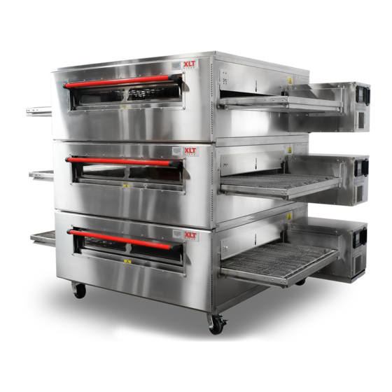
1. DESCRIPTION The XLT TS3-W series of ovens consist of seven models; the 1832-TS3-W, 2440-TS3-W, 3240-TS3- W, the 3255-TS3-W, the 3855-TS3-W, the 3270-TS3-W and the 3870-TS3-W. The first 2 digits of the model number represents the conveyor width, and the last two digits indicate the bake chamber length. Ovens with a longer bake chamber length have a higher cooking capacity. - Page 6 Figure 2: TS3-W Front View Figure 3: Right Hand Control Box (All TS3-W Models) Figure 4:Left Hand Control Box (3270-TS3-W and 3870-TS3-W) XD-9010-TS3-W-EN Rev A 04/2009 Installation & Operation Manual...
-
Page 7: Operator Controls
2. OPERATOR CONTROLS The operator controls for the TS3-W ovens are located on the Control Box which is on the right side of the oven also. The oven switch with the operating instructions is shown in Figure 5. Also nearby are the temperature control, the conveyor control, and the fuse bank, (see Figure 6). - Page 8 Figure 6: Right Hand Side Control Panel (All TS3-W Models) All XLT ovens have a right hand side Control Panel. The fuses are located on the Control Panel and are labeled for their function and replacement part number. It is very important to use only the fuses listed.
- Page 9 Figure 7: Left Hand Side Control Panel (3270-TS3-W and 3870-TS3-W) 3270-TS3-W and 3870-TS3-W ovens also have a left hand side Control Panel. This panel houses the fuses for the equipment inside the left hand control box. A second temperature control is also used for controlling the burner on the left half of the oven.
- Page 10 Figure 8: Optional Right Hand Control Panel (Split Belt Conveyor) TS3-W A popular option on the XLT oven is the split conveyor belt. This allows for 2 different conveyor speeds through the oven. Figure 8 shows the right hand control panel when the split belt option is present.
-
Page 11: Operation
3. OPERATION The XLT oven is a convection oven. It cooks foods by forcing hot air to circulate around the food, thereby increasing the heat transfer rate. Convection ovens generally cook foods faster than conventional ovens. The XLT oven models also have a conveyor that carries food through the oven at a uniform rate. -
Page 12: Detailed Start-Up Instructions
3.2. DETAILED START-UP INSTRUCTIONS 1. Turn the Oven switch on, (see Figure 5). The fan starts when the Oven switch is turned on. 2. Adjust the temperature controller set-point to desired temperature (see Figure 6). Figure 9: Temperature Controller See Figure 9 above to adjust the temperature controller. To change the oven Set Point temperature, press and hold either the Up or Down key for 2 seconds and then use these 2 keys to adjust to the desired temperature. -
Page 13: Shut Down Instructions
5. The conveyor is controlled by the Enter Key button. Push twice to turn off and repeat to turn on, (Figure 6). 6. Adjust the Conveyor Control to the desired belt time. The Conveyor Control will display the belt time. The Up or Down key will adjust the time accordingly. See Figure 10 below. Figure 10: Conveyor Control Display These controls are factory preset at 4:00 minutes minimum and 14:00 minutes maximum. -
Page 14: Specifications
4. SPECIFICATIONS Figure 11: Oven Size Specification Drawing XD-9010-TS3-W-EN Rev A 04/2009 Installation & Operation Manual... - Page 15 XD-9010-TS3-W-EN Rev A 04/2009 Installation & Operation Manual...
- Page 16 GENERAL SPECIFICATIONS (ALL OVENS) Oven ELECTRICAL REQUIREMENTS Single Stack Volts Amps Phase Frequency 1832-TS3-W 3.0 / 3.2 / 3.4 2440-TS3-W 3.0 / 3.2 / 3.4 3240-TS3-W 3.0 / 3.2 / 3.4 220/230/240 Single 50 Hz 3255-TS3-W 3.0 / 3.2 / 3.4 3855-TS3-W 3.0 / 3.2 / 3.4 3270-TS3-W...
- Page 17 QUIET FIRE BURNER - GAS REQUIREMENTS (INLET) Oven Natural Gas Propane Gas Single Stack 1832-TS3-W 15.23 kw 15.23 kw 2440-TS3-W 19.03 kw 19.03 kw 3240-TS3-W 26.35 kw 26.35 kw 3255-TS3-W 43.92 kw 43.92 kw 3855-TS3-W 43.92 kw 43.92 kw 3270-TS3-W 46.85 kw 46.85 kw 3870-TS3-W...
- Page 18 Natural Gas Propane Gas 3B/P (30) (30/37/50) (37) Gas Group Inlet pressure (mbar) 20/25 28/30/37/50 30/37/50 30/37/50 Main burner type (1) Quiet Fire Burner / (2) Quiet Fire Burners for 3270/3870 Number of injectors (1) per burner Main burner aeration Fixed opening size Ignition...
- Page 19 Gas Matrix by Country (single categories marketed): Natural Gas (8.75 mbar manifold) LP Gas (25 mbar manifold) Country Symbol 3B/P Germany Austria Belgium Denmark Spain Finland France Greece (?) Ireland Iceland (?) Italy Luxembourg Norway Netherlands Portugal United Kingdom Sweden Switzerland Slovenia Slovakia...
-
Page 20: Installation
5. INSTALLATION 5.1. INSTALLATION OVERVIEW The following is an overview of the installation process. 1. Read this manual thoroughly. 2. Make sure all electric, gas, and ventilation utilities are adequately sized and in place before the oven arrives. 3. Inspect the oven and crates for freight damage upon arrival. Assemble the oven on its base near the area of intended usage. -
Page 21: Physical Location & Spacing Requirements
150mm. See Section 7. Rough-In for gas and electrical connections, (page 29). 5.5. ELECTRICAL SUPPLY All XLT ovens require a 220-240VAC power supply. See General Specifications Chart for the electrical power requirements. When installed, the appliance must be electrically grounded in accordance with local codes. -
Page 22: Casters
5.7. CASTERS Because the oven(s) are equipped with casters, the installation must be made with a connector that complies with local standards. 5.8. RESTRAINT For all installations, a restraint must be provided to limit the movement of the oven without depending on the gas connector and the quick-disconnect device or its associated piping, and/or the electric cord, to limit the oven movement. -
Page 23: Ventilation Guidelines
expedite approval, reduce oven maintenance cost and provide a more comfortable working environment. Keep the appliance area free from ventilation obstructions. Proper ventilation is the oven owner’s responsibility. 5.9.2. VENTILATION GUIDELINES A ventilation hood that extends at least 300 mm from each side and at least 150 mm from the front must be used. -
Page 24: Hood Interconnection
5.9.4. HOOD INTERCONNECTION The following is a recommended method of providing an interlock system, (if required), between the ventilation fan in the hood and the XLT gas ovens. The circuit shown will stop the ovens from operating if the ventilation fan fails and also prevent the ovens from starting if the ventilation fan is not first operating. - Page 25 These ovens should be considered bakery type ovens. In the rare event fire protection has been required it is recommended that the fire protection be installed as noted below. This will provide the required protection without affecting oven function or cleaning. Figure 15: Fire Suppression View Fire Suppression plumbing may be installed as required by local code.
-
Page 26: Maintenance
5.9.6. MAINTENANCE The most critical item to be maintained is the filter on the Flow Path Pressure Generating fan (see Figure 6 page 7). The filter is held in place by a snap-on fan guard and can be washed several times. Regular cleaning of the Flow Path Pressure Generating fan filter is important to maintaining air circulation within the control box and providing combustion air. - Page 27 Example Cleaning Schedule for XLT Ovens Task Daily Weekly Monthly Semi- annual Wipe down front Clean sandwich window Wipe down sides Wipe down top Wipe down control box Wipe down motor cover Empty Crumb Trays Remove large debris from conveyor...
-
Page 28: Troubleshooting
8. Raw ingredient temperature (frozen?) 9. Quantity of toppings XLT ovens can be configured to cook a wide variety of food items. This is accomplished by arranging the fingers to control the baking characteristics. Generally speaking, most cooking is a “bottom up”... -
Page 29: Oven Problems
6.2. OVEN PROBLEMS When you suspect that something is wrong with the oven, Wolfe Electric, Inc. is committed to helping you to get your oven back in working order as soon as possible. Verify the following items and then contact us before performing maintenance and repairs. Electrical diagrams are located on page 32-34 and on the inside surface of the operator control panel lid. -
Page 30: Rough-In
7. ROUGH-IN 150 mm FROM BACK OF 17 mm MINIMUM (RECOMMENDED) OVEN TO WALL FROM FAN COVER TO WALL UTILITIES SHOULD BE EASILY ACCESSIBLE WITHOUT MOVING OVEN(S). AVOID, WHENEVER POSSIBLE, RUNNING THE UTILITIES BEHIND THE OVEN(S), AS THIS WILL AFFECT OVEN CLEARANCES TO WALL. TOP VIEW 76 mm (RECOMMENDED) - Page 31 The gas supply should have a gas meter and regulator large enough to handle all of the gas appliances, such as the furnace, hot water heater, and ovens, in operation at the same time. Add up all of the kw ratings to determine the total load.
- Page 32 . Below is listed the individual oven model specifications. Burner Cap. Nat. Gas Supply LP Gas Supply Oven Model kw/hr. (max) Pressure Per Oven Pressure Per Oven Quiet Fire Burner mbar mbar 1832-TS3-W Single 15.23 15-20 27.5-35 1832-TS3-W Double 30.46 15-20 27.5-35 1832-TS3-W Triple...
-
Page 33: Electrical Diagrams
8. ELECTRICAL DIAGRAMS: 8.1. 1832-TS3-W, 2440-TS3-W, 3240-TS3-W, 3255-TS3 & 3855-TS3-W XD-9010-TS3-W-EN Rev A 04/2009 Installation & Operation Manual... -
Page 34: 3270-Ts3-W & 3870-Ts3-W Right Hand Side
8.2. 3270-TS3-W & 3870-TS3-W RIGHT HAND SIDE XD-9010-TS3-W-EN Rev A 04/2009 Installation & Operation Manual... -
Page 35: 3270-Ts3-W & 3870-Ts3-W Left Hand Side
8.3. 3270-TS3-W & 3870-TS3-W LEFT HAND SIDE XD-9010-TS3-W-EN Rev A 04/2009 Installation & Operation Manual... - Page 36 XD-9010-TS3-W-EN Rev A 04/2009 Installation & Operation Manual...
Need help?
Do you have a question about the TS3-W World Series and is the answer not in the manual?
Questions and answers