Table of Contents
Advertisement
Quick Links
Read This Manual Before Using This Appliance.
Current versions of this manual, Rough-In Specifications, Installation & Operation Manual, Architectural
Drawings, & a list of International Authorized Distributors are available at:
For use with the following XLT Radiant Oven Versions:
Standard (S)
A
World (W)
A
Original Instructions
US: 888-443-2751 FAX: 316-943-2769
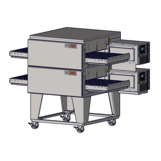
XLT Radiant Oven
Parts & Service Manual
2000887
XLT Ovens
PO Box 9090
Wichita, Kansas 67277
INTL: 316-943-2751
RD 9007A
SWA
08/01/2019
www.xltovens.com
WEB:
www.xltovens.com
Advertisement
Table of Contents

Related Manuals for XLT Ovens RD 9007 PS


Summary of Contents for XLT Ovens RD 9007 PS
- Page 1 Drawings, & a list of International Authorized Distributors are available at: www.xltovens.com For use with the following XLT Radiant Oven Versions: Standard (S) World (W) 2000887 XLT Ovens PO Box 9090 Original Instructions Wichita, Kansas 67277 US: 888-443-2751 FAX: 316-943-2769 INTL: 316-943-2751 WEB: www.xltovens.com...
-
Page 2: Table Of Contents
TABLE OF CONTENTS Warning & Safety Information......................3 General ............................... 6 Warranty ............................. 8 Recommended Tool List ........................10 Installation Responsibilities ......................11 Oven Theory of Operation ....................... 12 Oven Troubleshooting ........................17 Oven Service Procedures........................20 Oven Parts ............................22 Oven Schematics .......................... -
Page 3: Warning & Safety Information
WARNING & SAFETY INFORMATION XLT has spent millions of dollars designing and testing our products as well as developing Parts & Service Manuals. These manuals are the most complete and easiest to understand in the industry. However, they are worthless if they are not followed. We have witnessed store operators and building owners lose many thousands of dollars in lost revenue due to incorrect installations. - Page 4 WARNING & SAFETY INFORMATION SAFETY DEPENDS ON YOU This appliance is for professional use by qualified personnel. This appliance must be installed by qualified persons in accordance with the regulations in force. This appliance must be installed with sufficient ventilation to prevent the occurrence of unacceptable concentrations of substances harmful to health in the room in which it is installed.
- Page 5 Appliance is not to be cleaned with high pressure water. XLT ovens are certified for use in stacks of up to four (4) units of XLT products. Integration of other manufacturer’s products into an oven stack is not recommended, & will void any warran- ties.
-
Page 6: General
GENERAL This manual, which contains an illustrated parts breakdown, has been prepared as an aid in understanding how the unit operates, how to diagnose problems, and order parts for the equipment. All of the parts, listed in the parts breakdown, are manufactured with the same precision as the original equipment. - Page 7 This page intentionally left blank. Technical Support US: 888-443-2751 Technical Support INTL: 316-943-2751...
-
Page 8: Warranty
Warranty – US and Canada Rev A Approval Date: 08/01/2019 XLT warrants Radiant Ovens manufactured after August 01, 2019 to be free from any defect in material and workmanship under normal use for seven (7) years from the date of original purchase by the end user, and further warrants conveyor shafts and conveyor bearings for ten (10) years. - Page 9 Warranty – International Rev A Approval Date: 08/01/2019 XLT warrants Radiant Ovens manufactured after August 01, 2019 to be free from any defect in material and workmanship under normal use for five (5) years from the date of original purchase by the end user, and further warrants conveyor shafts, and conveyor bearings for ten (10) years.
-
Page 10: Recommended Tool List
RECOMMENDED TOOL LIST Sockets QTY. Ratchets QTY. Pliers QTY. 1/4" Drive 7" 1/4" Drive Diagonal SM 3/16 12" 3/8" Drive Diagonal Std 7/32 Slip Joint Std Extensions QTY. Needle Nose 9/32 1/4" Drive Wire Strippers 5/16 3" Wire Crimpers 6" 7/16 10"... -
Page 11: Installation Responsibilities
INSTALLATION RESPONSIBILITIES Service Owner/ Responsibility Company Contractor Site Survey: Verify electrical capabilities Assembly of new ovens per XLT Installation & Operation Manual Base assembled and set in place Ovens moved and stacked with proper lifting equipment Peel all PVC Connect cord anchorage to incoming electrical supply Connect electrical supply Connection may require Permit and Code Inspections Relocate Make-Up-Air to enter the room at the ends of the ovens... -
Page 12: Oven Theory Of Operation
OVEN THEORY OF OPERATION When the main power on the Large User Interface (LUI) is turned on: 1. The Fan (M3) located on the Control Panel will run. 2. The heating panels will begin to heat up. 3. The LUI will display actual temperature until set point is reached. 4. - Page 13 OVEN THEORY OF OPERATION H1-H4 - The Heating Elements convert electricity into heat through the process of joule heating. Electric current through the element encounters resistance, resulting in heating the element. The resistance values of the two (2) different part numbers used are: ...
- Page 14 OVEN THEORY OF OPERATION M3 - The Cooling fan provides cool air for the components inside the control box. It is controlled by turning on and off the main power button. A filter is provided to ensure clean air. 1) P1- Not Used - Digital Input 8) P9- Conveyor Motor 2) P2- RS-485 Cable To LUI 1) Motor SA...
- Page 15 OVEN THEORY OF OPERATION 1) COM– Line Voltage 2) N.O.- Switched Line Voltage 3) L2- High Limit Power 4) L1- High Limit Power 5) RTD S3 - The High Limit Switch is an electr onic, SPST (Single Pole Single Thr ow) switch. Its pur - pose is to provide fail safe operation.
- Page 16 OVEN THEORY OF OPERATION 2) TS1- Terminal Strip 1L) Power to SRC 1R) +24 VDC Out 2L) +24 VDC In 2R) Power To OMC1 & OMC2 3L) Power To Relay COM 3R) Power To M3 & C1 4L) Remote Switch 4R) Remote Switch 5L) -24 VDC 5R) -24 VDC To M3...
-
Page 17: Oven Troubleshooting
OVEN TROUBLESHOOTING Mechanical Function If your oven does not function properly, please verify the following conditions: 1. Check that the power cord to the oven is connected and/or plugged in if equipped with a plug and receptacle. 2. Check to see that the circuit breakers in the building electrical service panel have not been tripped or turned off. - Page 18 OVEN TROUBLESHOOTING LUI Service Error Codes Display Alarm MC LED Error Determination Troubleshooting Alarm LED on. Flash HEAT Temp Sensor Error, Open or Short. Perform a Hard Reset. If error still exists, TC1 FAILURE LED. All other LED's operate Temp <40F (4C) or >1200F contact XLT.
- Page 19 OVEN TROUBLESHOOTING LUI Service Error Codes Display Alarm MC LED Error Determination Troubleshooting Temp 50F over setpoint for period Alarm LED on. Flash HEAT U.L. Over Temp >1 minute. If user adjusts Perform a Hard Reset. If error still exists, LED.
-
Page 20: Oven Service Procedures
OVEN SERVICE PROCEDURES Large User Interface Programming Procedure Read the entire instruction before programming. Configuration Key Functions ENTER = Used to select and save parameters. UP = Increases the setting of the selected parameter. DOWN = Decrease the setting of the selected parameter. To enter factory tech mode press both UP and DOWN buttons simultaneously for ten (10) seconds and the following parameters will be displayed: 1. - Page 21 OVEN SERVICE PROCEDURES Conveyor Speed Settings Read the entire instruction before programming. Configuration Key Functions ENTER = Used to select and save parameters. HIDDEN = Behind the XLT is a hidden button. This is used along with the up and down button to access the programming mode.
-
Page 22: Oven Parts
OVEN PARTS How To Order Parts Below is a list of the information required for all purchase orders. Below the Bill of Materials (BOM) on the following parts summary pages are any additional information needed to order those parts. Oven information required: ... - Page 23 OVEN PARTS-OVERVIEW Oven Lid Conveyor Flap Conveyor Control Box Crumb Tray Product Stop Front Panel Locking Swivel Caster Control Box Lid Oven Control Large User Interface Control Panel Chain Guard Manual Drawer Technical Support US: 888-443-2751 Technical Support INTL: 316-943-2751...
- Page 24 OVEN PARTS-FRONT PANEL FRONT PANEL ITEM PART NUMBER DESCRIPTION YOUR PRICE RA 6500A Front Panel Assembly P.O.R RA 6700A Extended Front Panel P.O.R XA-6505 Front Panel Knob $15.90 XP 6506 Lifting Handle $45.90 Technical Support US: 888-443-2751 Technical Support INTL: 316-943-2751...
- Page 25 OVEN PARTS-HEATING PANEL HEATING PANEL ITEM PART NUMBER DESCRIPTION YOUR PRICE RA 5100-TLBR Heater Assembly (Top Left - Bottom Right) P.O.R RA 5100-TRBL Heater Assembly (Top Right - Bottom Left) P.O.R Heating Panel information required: Voltage Technical Support US: 888-443-2751 Technical Support INTL: 316-943-2751...
- Page 26 OVEN PARTS-CONVEYOR Standard Belt CONVEYOR ITEM PART NUMBER DESCRIPTION YOUR PRICE RA 7000A Conveyor Assembly Center P.O.R RA 7101 Conveyor Assembly Left P.O.R RA 7102 Conveyor Assembly Right P.O.R XA 7200 Conveyor Bearing Assembly $9.30 XM 7301 Conveyor Shaft Idle P.O.R XM 7302 Conveyor Shaft Drive...
- Page 27 OVEN PARTS-CONVEYOR Split Belt CONVEYOR ITEM PART NUMBER DESCRIPTION YOUR PRICE RA 7000A Conveyor Assembly Center P.O.R. RA 7101 Conveyor Assembly Left P.O.R. RA 7102 Conveyor Assembly Right P.O.R. XA 7200-SB Conveyor Bearing Assembly $17.80 XM 7303 Conveyor Shaft Idle P.O.R.
- Page 28 OVEN PARTS-BASE Technical Support US: 888-443-2751 Technical Support INTL: 316-943-2751...
- Page 29 OVEN PARTS-BASE BASE ITEM PART NUMBER DESCRIPTION YOUR PRICE XA 1001A Base Assembly P.O.R XM 1003 Base Leg P.O.R XM 1006 Side Leg Angle P.O.R XM 1007 Front/Back Leg Angle P.O.R XM 1008 Bolster Plate $11.50 XM 1010A Oven Lid P.O.R XP 1004 Caster...
- Page 30 OVEN PARTS-STANDARD CONTROL BOX Operating Position (shown with lid removed) Service Position Technical Support US: 888-443-2751 Technical Support INTL: 316-943-2751...
- Page 31 OVEN PARTS-CONTROL PANEL CONTROL PANEL ITEM PART NUMBER DESCRIPTION YOUR PRICE SP 4520-EL Fan Guard / Filter Holder $9.30 RP 4170A-LUI Large User Inferface $156.90 RP 4175A-MC Oven Control $215.90 XP 4501C-EL FPPG Fan EL M3 $31.00 XP 4520B-EL Fan Filter $1.95 Control Panel information required: Voltage...
- Page 32 OVEN PARTS-STANDARD CONTROL BOX FRONT CONTROL BOX FRONT ITEM PART NUMBER DESCRIPTION YOUR PRICE XA 4117A-12.5 RPM SB Conv Motor Assy 12.5 RPM SB $305.30 XA 4117A-12.5 RPM ST Conv Motor Assy 12.5 RPM STD $305.30 XP 4155 Sprocket Conveyor Drive 10T $15.70 Control Box Front information required: Split Belt or Standard Belt...
- Page 33 OVEN PARTS-STANDARD CONTROL BOX CONTROL BOX INTERIOR ITEM PART NUMBER DESCRIPTION YOUR PRICE RP 4701A-06 Terminal Strip 6 Place $9.00 RP 4717A Power Supply PS $21.60 RP 4724A Radiant Thermocouple Module $96.80 RP 4305A-25 Relay 25A Solid State $72.60 RP 4306A-50 50 Amp 3 Phase Contactor $91.20 XP 4305A-90-COV...
- Page 34 OVEN PARTS-WORLD CONTROL BOX CONTROL BOX INTERIOR ITEM PART NUMBER DESCRIPTION YOUR PRICE RP 4712A EMI Filter $89.60 RP 4717A Power Supply PS $21.60 RP 4724A Radiant Thermocouple Module $96.80 RP 4305A-25 Relay 25A Solid State $72.60 RP 4306A-50 50 Amp 3 Phase Contactor $91.20 XP 4305A-90-COV Relay 90A Cover...
- Page 35 OVEN PARTS-CONTROL BOX REAR CONTROL BOX REAR ITEM PART NUMBER DESCRIPTION YOUR PRICE RP 4302A Power Block $69.40 RP 4303A 3 Pole Circuit Breaker EL $98.90 XP 4515-CB-0.5A 1/2 Amp Circuit Breaker $7.30 Control Box Rear information required: Voltage Technical Support US: 888-443-2751 Technical Support INTL: 316-943-2751...
-
Page 36: Oven Schematics
OVEN SCHEMATIC - STANDARD 208/240 VAC LH Technical Support US: 888-443-2751 Technical Support INTL: 316-943-2751... - Page 37 OVEN SCHEMATIC - STANDARD 208/240 VAC RH Technical Support US: 888-443-2751 Technical Support INTL: 316-943-2751...
- Page 38 OVEN SCHEMATIC - WORLD 380 VAC LH Technical Support US: 888-443-2751 Technical Support INTL: 316-943-2751...
- Page 39 OVEN SCHEMATIC - WORLD 380 VAC RH Technical Support US: 888-443-2751 Technical Support INTL: 316-943-2751...
-
Page 40: Notes
NOTES Technical Support US: 888-443-2751 Technical Support INTL: 316-943-2751... - Page 41 This page intentionally left blank. Technical Support US: 888-443-2751 Technical Support INTL: 316-943-2751...
- Page 42 XLT Ovens PO Box 9090 Wichita, Kansas 67277 US: 888-443-2751 FAX: 316-943-2769 INTL: 316-943-2751 WEB: www.xltovens.com...
Need help?
Do you have a question about the RD 9007 PS and is the answer not in the manual?
Questions and answers