Table of Contents
Advertisement
Quick Links
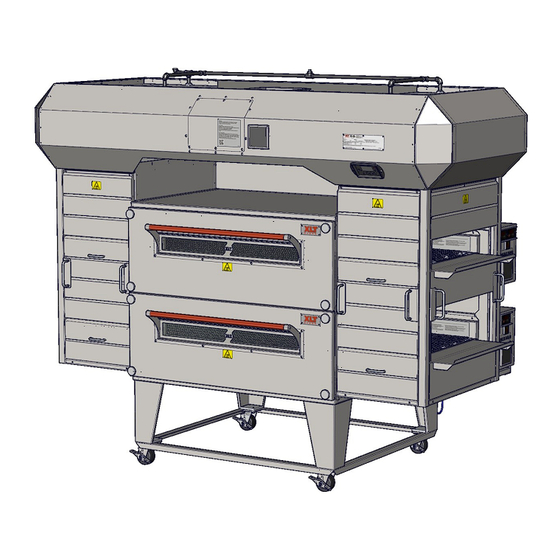
XLT Gas Oven & AVI Hood
This appliance is for professional use by qualified personnel. This appliance must be in-
stalled by qualified persons in accordance with the regulations in force. This appliance must be in-
stalled with sufficient ventilation to prevent the occurrence of unacceptable concentrations of sub-
stances harmful to health in the room in which it is installed. This appliance needs an unobstructed
flow of fresh air for satisfactory operation & must be installed in a suitably ventilated room in accor-
CAUTION
dance with current regulations. This appliance should be serviced by qualified personnel at least
every 12 months or sooner if heavy use is expected.
Electronic copies of this manual, Technical Specifications, Installation & Operation Manual, Architectural
Drawings, & a list of International Authorized Distributors are available at:
For use with the following XLT Gas Oven Versions:
Australia (AE)
E
Korea (K)
E
Standard (S)
E
World (W)
E
US: 888-443-2751 FAX: 316-943-2769
Parts & Service Manual
2000887
XLT Ovens
PO Box 9090
Wichita, Kansas 67277
INTL: 316-943-2751
For use with the following AVI Gas Hood Versions:
Standard (S)
E
World (W)
E
GAS40066
SAI Global
WEB:
www.xltovens.com
XD 9006B
AEKESWEHE
01/26/2016
www.xltovens.com
Advertisement
Table of Contents
Troubleshooting

Related Manuals for XLT Ovens XD 9006B


Summary of Contents for XLT Ovens XD 9006B
- Page 1 XD 9006B AEKESWEHE 01/26/2016 XLT Gas Oven & AVI Hood Parts & Service Manual This appliance is for professional use by qualified personnel. This appliance must be in- stalled by qualified persons in accordance with the regulations in force. This appliance must be in- stalled with sufficient ventilation to prevent the occurrence of unacceptable concentrations of sub- stances harmful to health in the room in which it is installed.
-
Page 2: Warning & Safety Information
Appliance is not to be cleaned with high pressure water. XLT ovens are certified for use in stacks of up to three (3) units of XLT products. Integration of other manufacturer’s products into an oven stack is not recommended, & voids any warran- ties. - Page 3 WARNING & SAFETY INFORMATION Definitions & Symbols A safety instruction (message) includes a “Safety Alert Symbol” & a signal word or phrase such as DANGER, WARNING or CAUTION. Each signal word has the following meaning: Indicates a potentially hazardous situation that, if not avoided, can result in serious injury or death.
-
Page 4: Warranty
The gas, electric, and HVAC utilities must be connected to the oven and installed by locally licensed contractors Failure to contact XLT Ovens prior to contacting a repair company for warranty work voids any and all warranties WHAT IS NOT COVERED: ... - Page 5 Warranty – International Rev G Approval Date: 12/01/2015 When purchased through an Authorized International Distributor, XLT warrants its products manufactured after July 1, 2014 to be free from any defect in material and workmanship under normal use. The Authorized International Distributor will repair XLT products during the warranty period. This warranty is extended to the original end user purchaser and is not transferable without prior written consent of the Authorized International Distributor.
-
Page 6: General
Please refer to it for descriptions, dimensions, weights, electrical requirements, maintenance schedules, and certifications. XLT Ovens wants you to be totally satisfied with every aspect of owning & using your oven & hood. Your feedback, both positive & negative, is very important to us as it helps us un- derstand how to improve our products &... -
Page 7: Table Of Contents
TABLE OF CONTENTS Warning & Safety Information..................... 2 Warranty ............................4 General ............................6 Oven Theory of Operation ......................8 Hood Theory of Operation ......................14 Oven Troubleshooting ........................ 17 Hood Troubleshooting ........................ 18 Oven Service Procedures......................20 Hood Service Procedures ......................26 Oven Parts .......................... -
Page 8: Oven Theory Of Operation
OVEN THEORY OF OPERATION When the Main Switch (S1) is turned on; 1. The Oven Fan Motor (M1) located in the Back Wall will run. 2. The Fan (M3) located on the Control Panel will run. 3. The Temperature Control (TC) will display both the actual and set-point temperatures. 4. - Page 9 OVEN THEORY OF OPERATION CC - The Conveyor Control is supplied 24 VDC by the Power Supply (PS) via a Circuit Breaker (CB6 & CB7, optional) to Terminals 4 & 5. The belt time is displayed, and is user-adjusted by pressing and holding the up or down arrow button switches.
- Page 10 OVEN THEORY OF OPERATION end of the Rectifier Plug is connected to Terminals 1 & 5 of the Main Valve (V1-V2). The V1-V2 valve will open, allowing fuel to flow into the burner. When the two simultaneous events occur, fuel flow and spark, ignition should occur. When flame is sensed by the FS, a DC signal is sent to Terminal S1 of the IC.
- Page 11 OVEN THEORY OF OPERATION T6, voltage continues from T9 for 30 minutes. T9 supplies voltage to the Main Fan Motor (M1) through a Circuit Breaker (CB2), and also supplies voltage to the FPPG (M3) Fan. M1 and M3 are the only components that will continue to operate for 30 minutes after S1 is turned off. The off delay relay is a safety feature to allow the oven to cool down to room temperature, and to eliminate heat stress on the components of the oven.
- Page 12 OVEN THEORY OF OPERATION SI - The Spark Igniter consists of a copper-clad metal mounting plate, and an electrode encapsu- lated in ceramic insulation. The insulated electrodes has a 1/4” male spade welded to it. This spade connects to the Spark Terminal on the Ignition Control (IC) via a spark wire. The end of this rod is positioned near the burner tube in such away so as to create a small gap.
- Page 13 This page intentionally left blank. Technical Support US: 888-443-2751 Technical Support INTL: 316-943-2751...
-
Page 14: Hood Theory Of Operation
HOOD THEORY OF OPERATION (STD w/FS) When any one of the three oven switches on the Hood User Interface (HUI) are touched (capacitive touch); 1. The Exhaust Fan Motor (M1) located on the roof will run. 2. The ovens associated with the corresponding switches will turn on. The first part of the Theory of Operation explains how electrical power is delivered to the hood and initial sequences when the HUI switch is turned on. - Page 15 HOOD THEORY OF OPERATION (STD w/FS) Touching the “Silver Square” buttons will turn each oven on or off and sequence the operation of the VFD and the MUA circuits. RS485 cable supplies power and communication between the HUI and HMC. HMC –...
- Page 16 HOOD THEORY OF OPERATION (STD w/FS) REC 1, 2, & 3 - These are electrical receptacles, which supply line voltage for the ovens. Each receptacle should have a 20A dedicated breaker supplied from the buildings electrical panel. Line voltage to each receptacle is supplied via HMC P3. If fire alarm is activated P3 will disrupt line voltage being supplied to receptacle shutting the oven off.
-
Page 17: Oven Troubleshooting
OVEN TROUBLESHOOTING Mechanical Function If your oven does not function properly, please verify the following conditions: 1. Verify that the power cord to the oven is connected and/or plugged in if equipped with a plug and receptacle. 2. Check all circuit breakers on the oven control panel to ensure they have not been tripped. 3. -
Page 18: Hood Troubleshooting
HOOD TROUBLESHOOTING Removing the hood VFD cover panel exposes high voltage. Proceed with cau- tion and read the following the instructions carefully. HIGH VOLTAGE Initial troubleshooting of the hood: 1. Remove panel covering VFD to check and see if the circuit breaker is tripped. 2. - Page 19 This page intentionally left blank. Technical Support US: 888-443-2751 Technical Support INTL: 316-943-2751...
-
Page 20: Oven Service Procedures
OVEN SERVICE PROCEDURES Conveyor Control Programming Procedure Read the entire instruction before programming. Configuration Key Functions < L > = Behind the <L> in XLT is a hidden button. This is used along with the up and down button to access the programming mode. Use this after each step to advance to the next parameter when programming. - Page 21 OVEN SERVICE PROCEDURES Temperature Control Programming Procedure Read the entire instruction before programming. Ser1 5˚C/22˚F 315˚C/600˚F 4-20 AL1.P H.A. Configuration Button Functions nonE <FUNC> =The new setting of the selected parameter is stored and the SFtA display advances to the next parameter. This is required be- Table 1 tween each parameter.
- Page 22 OVEN SERVICE PROCEDURES Multi-Valve Adjustment Procedure Check Incoming Pressure: Loosen screw 1 full turn counter clockwise (Figure 1) Connect Manometer to this test port Turn main switch to on position and wait for burner to light (up to 30 seconds) ...
- Page 23 OVEN SERVICE PROCEDURES Multi-Valve Adjustment Procedure Check High Bias Pressure: Loosen screw 1 full turn counter-clockwise (Figure 3) Connect Manometer to this test port Turn main switch to on position and wait for burner to light (up to 30 seconds) Figure 3 ...
- Page 24 OVEN SERVICE PROCEDURES Multi-Valve Adjustment Procedure Multi-Valve Adjustment Settings Natural Gas LP Gas All Oven Models mbar mbar High Flame Bias 8.75 0.875 Low Flame Bias 0.25 0.025 1.25 0.125 Figure 5 Check Low Bias Pressure: Pull one of the two blue wires going into the modulating valve. (This simulates a temperature drop and allows the oven to run at Low Flame Bias) If the flame goes out turn the 5mm screw clockwise 1 turn to increase Low Flame Bias...
- Page 25 OVEN SERVICE PROCEDURES Multi-Valve Adjustment Procedure Remove the Manometer : Turn main switch to the off position Remove the manometer and re tighten the screw (Figure 7) (Note: Do not over tighten the screw only snug is needed) Figure 7 Air Shutter Settings Optical Flame Sensor...
-
Page 26: Hood Service Procedures
HOOD SERVICE PROCEDURES Allen Bradley Power Flex 4M Restoring AVI Defaults Read the entire instruction before programming. To reset VFD settings change P112 to 1. The VFD will reset to factory default settings. To cycle power, turn circuit breaker off and on and the HMC will load the factory parameters into the VFD. P105=65 Maximum Frequency P106=2... - Page 27 HOOD SERVICE PROCEDURES VFD Controller Settings Switches On 1832 & 2440 3240, 3255 & 3270 3855 & 3870 Top Middle Bottom Single 20 Hz 25 Hz 30 Hz 20 Hz 25 Hz 30 Hz Double 35 Hz 40 Hz 45 Hz 35 Hz 40 Hz 45 Hz...
- Page 28 PARTS How to order Parts Have all information ready when calling XLT. Below is a list of information that is required for all orders. At the bottom of the Bill of Materials (BOM) on the following parts overview pages are additional requirements needed depending on your parts order.
-
Page 29: Oven Parts
OVEN PARTS-OVERVIEW Technical Support US: 888-443-2751 Technical Support INTL: 316-943-2751... - Page 30 OVEN PARTS-FRONT PANEL FRONT PANEL ITEM PART NUMBER DESCRIPTION YOUR PRICE XA 6500 Front Panel Assembly P.O.R XA 6505 Front Panel Knob $15.90 XA 6600 Sandwich Door P.O.R XF 126-2 Screw 10-24 P.O.R XM 6703 Door Retainer Left $13.80 XM 6704 Door Retainer Right $13.80 Technical Support US: 888-443-2751...
- Page 31 OVEN PARTS-FRONT PANEL EXTENDED FRONT PANEL ITEM PART NUMBER DESCRIPTION YOUR PRICE XA 6700 Extended Front Panel P.O.R XA 6504 Front Panel Knob Assy Ext Frt $33.09 XP 6505 Front Panel Knob $14.49 Front Panel information required: Size of Oven Short or Long Window Stainless or Wood Handle 3”...
- Page 32 OVEN PARTS-BACK WALL Technical Support US: 888-443-2751 Technical Support INTL: 316-943-2751...
- Page 33 OVEN PARTS-BACK WALL BACK WALL ITEM PART NUMBER DESCRIPTION YOUR PRICE XA 50 Back Wall Assembly P.O.R SP 5009A-75 Fan Motor w/ Mount 3/4 HP $283.20 XA 5200 Fan Blade P.O.R Back Wall information required: Size of Oven Voltage Technical Support US: 888-443-2751 Technical Support INTL: 316-943-2751...
- Page 34 OVEN PARTS-CONVEYOR Conveyor Drive Chain not shown Technical Support US: 888-443-2751 Technical Support INTL: 316-943-2751...
- Page 35 OVEN PARTS-CONVEYOR CONVEYOR ITEM PART NUMBER DESCRIPTION YOUR PRICE XA 7000 Conveyor Assembly P.O.R XA 7200 Conveyor Bearing Assembly $9.30 XM 7301 Conveyor Shaft Idle P.O.R XM 7302 Conveyor Shaft Drive P.O.R XP 7403 Conveyor Roll Notched $12.20 XP 7404 Conveyor Roll Plain $11.00 XP 9503...
- Page 36 OVEN PARTS-BASE Technical Support US: 888-443-2751 Technical Support INTL: 316-943-2751...
- Page 37 OVEN PARTS-BASE BASE ITEM PART NUMBER DESCRIPTION YOUR PRICE XA 1001 Base Assembly P.O.R XM 1003-15 Base Leg $65.40 XM 1006 Side Leg Angle P.O.R XM 1007 Front/Back Leg Angle P.O.R XM 1008 Bolster Plate $11.50 XM 1010 Oven Lid P.O.R XP 1004 Caster...
- Page 38 OVEN PARTS-FINGER GROUP Technical Support US: 888-443-2751 Technical Support INTL: 316-943-2751...
- Page 39 OVEN PARTS-FINGER GROUP FINGERS ITEM PART NUMBER DESCRIPTION YOUR PRICE XA 8Xxxxx Finger Group Assembly P.O.R XA 8001-B Finger Body Bottom P.O.R XA 8001-T Finger Body Top P.O.R XM 8004 Finger InnerPlate Perforated P.O.R XM 8009-S Finger Block Off Plate $12.60 XM 8024 EndLoss Plate...
- Page 40 OVEN PARTS-STANDARD CONTROL BOX Operating Position (shown with lid removed) Service Position Technical Support US: 888-443-2751 Technical Support INTL: 316-943-2751...
- Page 41 OVEN PARTS-STANDARD CONTROL BOX CONTROL PANEL ITEM PART NUMBER DESCRIPTION YOUR PRICE SP 4520-GA Fan Guard / Filter Holder $5.60 XP 4501-S FPPG Fan Standard M2 $36.20 XP 4507-24-A Conveyor Speed Control 24VDC $277.10 XP 4508 Temperature Control GAS $298.30 XP 4515-CB Circuit Breaker $6.95...
- Page 42 OVEN PARTS-STANDARD CONTROL BOX CONTROL BOX FRONT ITEM PART NUMBER DESCRIPTION YOUR PRICE XA 4117-12.5 RPM STD Conv Motor Assy 12.5 RPM STD $305.30 XP 4155 Sprocket Conveyor Drive 10T $15.70 XP 4101 Switch Operator $21.40 XP 4102 Contact Block 1 Pole w/Mount $21.40 Control Box Front information required: Size of Oven...
- Page 43 OVEN PARTS-STANDARD CONTROL BOX CONTROL BOX BACK ITEM PART NUMBER DESCRIPTION YOUR PRICE XA 4211-DC UV Flame Detector Wire Plug $11.46 XA 4235 Rectifier Plug Assy $15.80 XP 4207-DI Multi-Valve V1 & V2 $107.30 XP 4210-UV-DC Flame Detector 24VDC $109.00 XP 4509 Thermocouple Type K 48 (RH) $31.80...
- Page 44 OVEN PARTS-STANDARD CONTROL BOX CONTROL BOX REAR ITEM PART NUMBER DESCRIPTION YOUR PRICE XA 9301 Power Cord Assembly $28.40 Control Box Rear information required: Size of Oven Voltage BURNER ITEM PART NUMBER DESCRIPTION YOUR PRICE XA 4203-DI-SQ FS/SI Assembly $52.90 Technical Support US: 888-443-2751 Technical Support INTL: 316-943-2751...
- Page 45 OVEN PARTS-STANDARD CONTROL BOX Burner information required: Size of Oven NATURAL GAS VALVE ITEM PART NUMBER DESCRIPTION YOUR PRICE SP 9910-QF-Nat Natural Gas Conversion Kit $12.20 PROPANE VALVE ITEM PART NUMBER DESCRIPTION YOUR PRICE SP 9910-QF-Pro Propane Conversion Kit $36.50 Burner information required: Size of Oven Technical Support US: 888-443-2751...
- Page 46 OVEN PARTS-WORLD CONTROL BOX Operating Position (shown with lid removed) Service Position Technical Support US: 888-443-2751 Technical Support INTL: 316-943-2751...
- Page 47 OVEN PARTS-WORLD CONTROL BOX CONTROL PANEL ITEM PART NUMBER DESCRIPTION YOUR PRICE SP 4520-GA Fan Guard / Filter Holder $5.60 XP 4501-W FPPG Fan Standard M2 $33.70 XP 4507-24-A Conveyor Speed Control 24VDC $277.10 XP 4508 Temperature Control GAS $298.30 XP 4515-CB Circuit Breaker $6.95...
- Page 48 OVEN PARTS-WORLD CONTROL BOX CONTROL BOX FRONT ITEM PART NUMBER DESCRIPTION YOUR PRICE XA 4117-12.5 RPM STD Conv Motor Assy 12.5 RPM STD $305.30 XP 4155 Sprocket Conveyor Drive 10T $15.70 XP 4101 Switch Operator $21.40 XP 4102 Contact Block 1 Pole w/Mount $21.40 Control Box Front information required: Size of Oven...
- Page 49 OVEN PARTS-WORLD CONTROL BOX CONTROL BOX BACK ITEM PART NUMBER DESCRIPTION YOUR PRICE XA 4211-DC UV Flame Detector Wire Plug $11.46 XA 4235 Rectifier Plug Assy $15.80 XP 4207-DI Multi-Valve V1 & V2 $107.30 XP 4210-UV-DC Flame Detector 24 VDC $109.00 XP 4509 Thermocouple Type K 48 (RH)
- Page 50 OVEN PARTS-WORLD CONTROL BOX BURNER ITEM PART NUMBER DESCRIPTION YOUR PRICE XA 4203-DI-SQ FS/SI Assembly $52.90 Technical Support US: 888-443-2751 Technical Support INTL: 316-943-2751...
- Page 51 OVEN PARTS-WORLD CONTROL BOX NATURAL GAS VALVE ITEM PART NUMBER DESCRIPTION YOUR PRICE SP 9910-QF-Nat Natural Gas Conversion Kit $12.20 Burner information required: Size of Oven PROPANE VALVE ITEM PART NUMBER DESCRIPTION YOUR PRICE SP 9910-QF-Pro Propane Conversion Kit $36.50 Burner information required: Size of Oven Technical Support US: 888-443-2751...
- Page 52 This page intentionally left blank. Technical Support US: 888-443-2751 Technical Support INTL: 316-943-2751...
-
Page 53: Hood Parts
HOOD PARTS-OVERVIEW Main Canopy VFD Exhaust Fan Controller Front Shroud Panel End Shroud Panel (size specific) Technical Support US: 888-443-2751 Technical Support INTL: 316-943-2751... - Page 54 VFD CONTROL BOX VFD Control Box w/Fire Suppression Terminal Strips (TS) Hood Machine Control (HMC) Power Supply (PS) VFD Controller (VFD) Hood User Interface (HUI) Circuit Breaker (CB) Fire Suppression Relay (R1) Time Delay Relay (R2) VFD Control Box (Cover removed) Technical Support US: 888-443-2751 Technical Support INTL: 316-943-2751...
- Page 55 HOOD PARTS - VFD CONTROL BOX VFD W/ FIRE SUPPRESION ITEM PART NUMBER DESCRIPTION YOUR PRICE HP-1251 Light Assembly $57.80 HP-2058 Ground Bar 7 POS $55.70 HP-2060 Circuit Breaker Exhaust Fan $52.30 HP-2067-24VDC Relay 8 Pin 30A 24 VDC $23.70 HP-2070-MC Hood Machine Control P.O.R...
- Page 56 This page intentionally left blank. Technical Support US: 888-443-2751 Technical Support INTL: 316-943-2751...
-
Page 57: Oven Schematics
OVEN SCHEMATIC - STANDARD 1 BOX 120 VAC Technical Support US: 888-443-2751 Technical Support INTL: 316-943-2751... - Page 58 58 OVEN SCHEMATIC - WORLD & KOREA 1 BOX 230 VAC Technical Support US: 888-443-2751 Technical Support INTL: 316-943-2751...
- Page 59 OVEN SCHEMATIC - AUSTRALIA 1 BOX 230 VAC Technical Support US: 888-443-2751 Technical Support INTL: 316-943-2751...
- Page 60 OVEN SCHEMATIC - STANDARD 2 BOX LH 120 VAC Technical Support US: 888-443-2751 Technical Support INTL: 316-943-2751...
- Page 61 OVEN SCHEMATIC - STANDARD 2 BOX RH 120 VAC Technical Support US: 888-443-2751 Technical Support INTL: 316-943-2751...
- Page 62 62 OVEN SCHEMATIC - WORLD & KOREA 2 BOX LH 230 VAC Technical Support US: 888-443-2751 Technical Support INTL: 316-943-2751...
- Page 63 OVEN SCHEMATIC - WORLD & KOREA 2 BOX RH 230 VAC Technical Support US: 888-443-2751 Technical Support INTL: 316-943-2751...
- Page 64 OVEN SCHEMATIC - AUSTRALIA 2 BOX LH 230 VAC Technical Support US: 888-443-2751 Technical Support INTL: 316-943-2751...
- Page 65 OVEN SCHEMATIC - AUSTRALIA 2 BOX RH 230 VAC Technical Support US: 888-443-2751 Technical Support INTL: 316-943-2751...
-
Page 66: Hood Schematics
HOOD SCHEMATIC - STANDARD w/FS-w/VFD Technical Support US: 888-443-2751 Technical Support INTL: 316-943-2751... - Page 67 HOOD SCHEMATIC - WORLD w/FS-w/VFD Technical Support US: 888-443-2751 Technical Support INTL: 316-943-2751...
- Page 68 HOOD SCHEMATIC w/oFS-w/oVFD Technical Support US: 888-443-2751 Technical Support INTL: 316-943-2751...
- Page 69 This page intentionally left blank. Technical Support US: 888-443-2751 Technical Support INTL: 316-943-2751...
- Page 70 XLT Ovens PO Box 9090 Wichita, Kansas 67277 US: 888-443-2751 FAX: 316-943-2769 INTL: 316-943-2751 WEB: www.xltovens.com...
Need help?
Do you have a question about the XD 9006B and is the answer not in the manual?
Questions and answers