HP Z220 SFF Maintenance And Service Manual
Hide thumbs
Also See for Z220 SFF:
- User manual (67 pages) ,
- Specification (49 pages) ,
- Brochure & specs (2 pages)

Related Manuals for HP Z220 SFF


Summary of Contents for HP Z220 SFF
- Page 1 HP Z220 SFF, Z220 CMT, Z420, Z620, and Z820 Workstations Maintenance and Service Guide...
- Page 2 Agency. merchantability and fitness for a particular purpose, and is subject to change without notice. The warranties for HP products are set forth in the express limited warranty statements accompanying such products. Nothing herein should be construed as constituting an additional warranty.
-
Page 3: About This Guide
Configuring password security and resetting CMOS on page 158 Linux technical notes on page 162 Configuring RAID devices on page 166 System board designators on page 178 NOTE: View the HP Z220 SFF, Z220 CMT, Z420, Z620, and Z820 Workstation Series User Guide at http://www.hp.com/support/workstation_manuals. - Page 4 About this guide...
-
Page 5: Table Of Contents
Table of contents 1 Hardware overview ......................1 HP Z220 SFF Workstation components ..................1 HP Z220 SFF Workstation front panel components ............2 HP Z220 SFF Workstation rear panel components ............3 HP Z220 SFF Workstation chassis components ............. 4 HP Z220 SFF Workstation system board component ............ - Page 6 Installing a remote system ..................61 Copying a setup configuration to another computer ............. 62 Updating and managing software ................63 HP Client Management Solutions ................63 Altiris Client Management Solutions ................63 HP SoftPaq Download Manager ................64 System Software Manager ..................64 ROM Flash ......................
- Page 7 Clearing passwords ..............74 Chassis security ..................74 Smart Cover Sensor (optional) ............ 74 Side access panel solenoid lock (HP Z420 Workstation only) ..75 Cable lock (optional) ..............75 Fault notification and recovery .................. 75 Drive Protection System ................75 ECC fault prediction .................
- Page 8 Drive installation and cabling scenarios ............95 HP Z220 SFF Workstations — SATA cable connection guidelines . . . 95 HP Z220 CMT Workstations — SATA cable connection guidelines ................95 HP Z420 Workstations — Intel AHCI SATA controller guidelines ..96 HP Z420 Workstations —...
- Page 9 History tab .................... 141 Errors tab ....................142 Help tab ....................142 Saving and printing information in HP Vision Diagnostics ........... 143 Self-troubleshooting with HP Advanced System Diagnostics UEFI ..........144 Downloading HP Advanced System Diagnostics ............145 Accessing HP Advanced System Diagnostics ............146 User interface .......................
- Page 10 Performance considerations ..................176 Configuring software RAID ..................177 Appendix C System board designators ................178 HP Z220 SFF Workstation ..................... 178 HP Z220 CMT Workstation ....................179 HP Z420 and Z620 Workstation system board designators ............180 HP Z820 Workstations ......................182...
- Page 11 Index ..........................185...
-
Page 13: Hardware Overview
For complete and current information on supported accessories and components for the workstation, see http://partsurfer.hp.com. Topics HP Z220 SFF Workstation front panel components on page 2 HP Z220 SFF Workstation rear panel components on page 3 HP Z220 SFF Workstation chassis components on page 4... -
Page 14: Hp Z220 Sff Workstation Front Panel Components
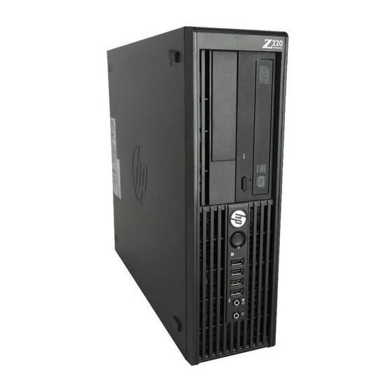
HP Z220 SFF Workstation front panel components Figure 1-1 Front panel components Table 1-1 Component description Optional media card reader (shown) Optical drive or optional second hard disk drive Hard drive or optical drive activity Power button light USB 2.0 ports (4, black) -
Page 15: Hp Z220 Sff Workstation Rear Panel Components
Simultaneous usage of integrated Intel HD graphics and discrete graphics cards (in order to drive more than two displays) can be enabled using the Computer (F10) Setup Utility. However, HP recommends using only discrete graphics cards when attaching three or more displays. -
Page 16: Hp Z220 Sff Workstation Chassis Components
HP Z220 SFF Workstation chassis components For complete and current information on supported accessories and components for the computer, see http://partsurfer.hp.com. The following image shows the components of a typical computer layout. Drive configurations can vary. Figure 1-3 Chassis components... -
Page 17: Hp Z220 Sff Workstation System Board Component
HP Z220 SFF Workstation system board component The following illustration and table identify computer system board components. Figure 1-4 System board component locations Table 1-4 System board component descriptions SATA Power Display Port AHCI 3Gb/s Battery Front audio AHCI 6Gb/s... -
Page 18: Hp Z220 Sff Workstation System Board Architecture
HP Z220 SFF Workstation system board architecture This section describes the system architectures. The following figure shows the typical system board block diagram. Figure 1-5 System board block diagram Z220 SFF Block Diagram Last Modified on:1/11/12 DDR3 PCIe 3.0 x16... -
Page 19: Workstation Specifications
NOTE: To drive more than two displays, use the Computer (F10) Setup Utility to intermix integrated Intel HD graphics and discrete graphics cards (with three or more displays, HP recommends using only discrete graphics cards). RAID configurations for SATA RAID levels 0, 1 ●... -
Page 20: Hp Z220 Cmt Workstation Components
HP Z220 CMT Workstation rear panel components on page 10 HP Z220 SFF Workstation chassis components on page 4 HP Z220 SFF Workstation system board component on page 5 HP Z220 SFF Workstation system board architecture on page 6 Chapter 1 Hardware overview... -
Page 21: Hp Z220 Cmt Workstation Front Panel Components
HP Z220 CMT Workstation front panel components Figure 1-6 Front panel components Table 1-5 Component descriptions Optical drive USB 3.0 ports (2) (blue) Power button Headphone connector Hard drive activity light Microphone connector 1394a FireWire connector (optional USB 2.0 ports (1) (black) -
Page 22: Hp Z220 Cmt Workstation Rear Panel Components
Simultaneous usage of integrated Intel HD graphics and discrete graphics cards (in order to drive more than two displays) can be enabled using the Computer (F10) Setup Utility. However, HP recommends using only discrete graphics cards when attaching three or more displays. -
Page 23: Hp Z220 Cmt Workstation Chassis Components
HP Z220 CMT Workstation chassis components The following figure shows the chassis components of a typical HP Z220 CMT Workstation layout. Drive configurations can vary. Figure 1-8 Chassis components Table 1-7 Workstation component descriptions Item Description Item Description Power supply... -
Page 24: Hp Z220 Cmt Workstation System Board Component
HP Z220 CMT Workstation system board component The following illustration and table identify workstation system board components. Figure 1-9 System board component locations 31 32 Table 1-8 System board component descriptions SATA Power Display Port AHCI 3Gb/s Battery DVI video... -
Page 25: Hp Z220 Cmt Workstation System Board Architecture
HP Z220 CMT Workstation system board architecture The following figure shows the typical system board block diagram. Figure 1-10 System board block diagram Z220 CMT Block Diagram DDR3 PCIe 3.0 x16 1600 MHz ECC/NonECC Intel Socket PCIe 2.0 x4 w/ x16... -
Page 26: Workstation Specifications
NOTE: To drive more than two displays, use the Computer (F10) Setup Utility to intermix integrated Intel HD graphics and discrete graphics cards (with three or more displays, HP recommends using only discrete graphics cards). RAID configurations for SATA RAID levels 0, 1 ●... -
Page 27: Hp Z420 Workstation Components
HP Z420 Workstation rear panel on page 17 HP Z420 Workstation chassis components on page 18 HP Z420 Workstation system board components on page 19 HP Z420 Workstation system board architecture on page 20 HP Z420 Workstation specifications on page 21... -
Page 28: Hp Z420 Workstation Front Panel
HP Z420 Workstation front panel Figure 1-11 Front panel components Table 1-9 Component descriptions Optical drive USB 3.0 ports (2, blue) Power button Headphone connector Hard drive activity light Microphone connector USB 2.0 port (black) IEEE–1394a connector Chapter 1 Hardware overview... -
Page 29: Hp Z420 Workstation Rear Panel
HP Z420 Workstation rear panel Figure 1-12 Rear panel components Table 1-10 Component descriptions Power supply Built-In Self Test Audio line-out connector (green) (BIST) LED Universal chassis clamp opening Microphone connector (pink) AMT-enabled RJ-45 network PS/2 mouse connector (green) connector (orange) USB 2.0 ports (4, black) -
Page 30: Hp Z420 Workstation Chassis Components
HP Z420 Workstation chassis components Figure 1-13 Chassis components Table 1-11 Component descriptions Power supply Side access panel Memory module (DIMM) Rear system fan System board Memory airflow guide PCIe card Hard disk drive PCI card Hard disk drive Speaker... -
Page 31: Hp Z420 Workstation System Board Components
HP Z420 Workstation system board components Figure 1-14 System board component locations Table 1-12 System board component descriptions SATA (SAS optional) Cooling Security Front 1394a AHCI 3Gb/s CPU0 fan Chassis solenoid lock Front audio AHCI 6Gb/s Front fan Chassis intrusion sensor... -
Page 32: Hp Z420 Workstation System Board Architecture
HP Z420 Workstation system board architecture Figure 1-15 HP Z420 Workstation system board block diagram NOTE: The PCIe designators indicate the mechanical connector size and number of electrical PCIe lanes routed to an expansion slot. For example, x16(8) means that the expansion slot is mechanically a x16 length connector, with 8 PCIe lanes supported. -
Page 33: Hp Z420 Workstation Specifications
Intel QuickPath Interconnect (QPI) connects processors and I/O controller with speeds ● up to 8 GT/s HP Liquid Cooling option is available for all Z420 processors and is required on the E5-2687W processor model. 600W Gold, 90% efficient, wide-ranging, active Power Factor Correction, two ●... - Page 34 Standard configuration: 13.2 kg (29.2 lb) ● Weight Minimum configuration: 12.5 kg (27.5 lb) ● Maximum configuration: 17.7 kg (39.4 lb) ● Tower configuration: Desktop configuration: Height: 44.76 cm (17.62 in) Height: 17.78 cm (7.00 in) ● ● Chassis dimensions Width: 17.78 cm (7.00 in) Width: 44.76 cm (17.62 in) ●...
-
Page 35: Hp Z620 Workstation Components
HP Z620 Workstation rear panel on page 24 HP Z620 Workstation chassis components on page 25 HP Z620 Workstation system board components on page 26 HP Z620 Workstation system board architecture on page 27 HP Z620 Workstation specifications on page 28... -
Page 36: Hp Z620 Workstation Rear Panel
HP Z620 Workstation rear panel Figure 1-17 Rear panel components Table 1-14 Component descriptions Power cord connector Audio line-out connector (green) PS/2 mouse connector (green) Microphone connector (pink) USB 2.0 ports (4, black) USB 3.0 ports (2, blue) RJ-45 network connectors (orange) -
Page 37: Hp Z620 Workstation Chassis Components
HP Z620 Workstation chassis components Figure 1-18 Chassis components Table 1-15 Component descriptions Side access panel Second CPU memory module (DIMM) (optional) Second CPU module rear guide bracket Memory fans Second CPU module (optional) Rear system fans PCIe card Power supply... -
Page 38: Hp Z620 Workstation System Board Components
HP Z620 Workstation system board components Figure 1-19 System board component locations Second CPU Module Second CPU Module Second CPU Module Second CPU Module Connector Connector Table 1-16 System board components descriptions PCI/PCIe Power Front 1394a PCIe2 x4 (1) Battery... -
Page 39: Hp Z620 Workstation System Board Architecture
HP Z620 Workstation system board architecture Figure 1-20 System board block diagram NOTE: The PCIe designators indicate the mechanical connector size and number of electrical PCIe lanes routed to an expansion slot. For example, x16 (8) means that the expansion slot is mechanically a x16 length connector, with 8 PCIe lanes supported. -
Page 40: Hp Z620 Workstation Specifications
HP Z620 Workstation specifications Intel Series C602 chipset with: ® Support for the Intel® Xeon™ Processor E5-1600 Series and E5-2600 Series ● Integrated 4-channel memory controller ● Processor Microarchitecture improvements ● technology Large L3 cache for superior performance ● Intel QuickPath Interconnect (QPI) connects processors and I/O controller with speeds up to 8 ●... - Page 41 ● Weight Minimum configuration: 15.5 kg (34.2 lb) ● Maximum configuration: 22.6 kg (49.9 lb) ● Height: 44.45 cm (17.50 in) ● Chassis Width: 17.15 cm (6.75 in) ● dimensions Depth: 46.48 cm (18.30 in) ● HP Z620 Workstation components...
-
Page 42: Hp Z820 Workstation Components
HP Z820 Workstation components For information on supported accessories and components, see http://partsurfer.hp.com. Topics HP Z820 Workstation system board architecture on page 34 HP Z820 Workstation chassis components on page 32 HP Z820 Workstation front panel on page 30 HP Z820 Workstation rear panel on page 31... -
Page 43: Hp Z820 Workstation Rear Panel
HP Z820 Workstation rear panel Figure 1-22 Rear panel components Table 1-18 Component descriptions Power cord connector USB 3.0 ports (2, blue) PS/2 mouse connector (green) USB 2.0 ports (4, black) Audio line-in connector (blue) Audio line-out connector (green) RJ-45 network connectors (2, orange) -
Page 44: Hp Z820 Workstation Chassis Components
HP Z820 Workstation chassis components Figure 1-23 Chassis components Table 1-19 Component descriptions CPU/memory fans Processor (CPU) heatsink Power supply Processor (CPU) Optical drive Chassis Side access panel Processor (CPU) liquid cooling unit (optional upgrade to standard heatsink) Side access panel key lock... -
Page 45: Hp Z820 Workstation System Board Components
HP Z820 Workstation system board components Figure 1-24 System board component locations Table 1-20 System board component descriptions PCI/PCIe Power Front 1394a PCIe3 x8 (4) — CPU0 Battery Front audio PCIe3 x16 — CPU0 CPU0 power Front USB 2.0 PCIe3 x16 (8) — CPU1 CPU1 power Front USB 3.0... -
Page 46: Hp Z820 Workstation System Board Architecture
HP Z820 Workstation system board architecture Figure 1-25 System board block diagram NOTE: The PCIe designators indicate the mechanical connector size and number of electrical PCIe lanes routed to an expansion slot. For example, x16(8) means that the expansion slot is mechanically a x16 length connector, with 8 PCIe lanes supported. -
Page 47: Hp Z820 Workstation Specifications
Intel QuickPath Interconnect (QPI) connects processors and I/O controller with speeds up to 8.0 ● GT/s NOTE: HP Liquid Cooling option is available for all Z820 processors. 850W Silver, 88% efficient, wide-ranging, active Power Factor Correction, two auxiliary dongles ● on two separate 12V rail, ERP 0.5W, Built-in-Self Test (BIST) 1125W Gold, 90% efficient, wide-ranging, active Power Factor Correction, three auxiliary ●... -
Page 48: Chapter 1 Hardware Overview
SATA RAID 0/1/5/10 on SCU ● SAS RAID 0/1/10 on LSI SAS 2308 controller ● Six SATA ports: four SCU (3 GB/s); two AHCI (6 GB/s) ● I/O technology Eight SAS ports (6 GB/s) ● Two ports (6.0 GB/s) available for optional eSATA ●... -
Page 49: Environmental Specifications
Values do not indicate continuous vibration. ENERGY STAR qualification HP computers marked with the ENERGY STAR logo are compliant with the applicable U.S. Environmental Protection Agency (EPA) ENERGY STAR specifications for computers. The EPA ENERGY STAR logo does not imply endorsement by the EPA. As an ENERGY STAR Partner, Hewlett-Packard Company has determined the products marked with the ENERGY STAR logo are ENERGY STAR qualified per the applicable ENERGY STAR guidelines for energy efficiency. -
Page 50: Ensuring Proper Ventilation
Ensuring proper ventilation Proper ventilation for the system is important for workstation operation. Follow these guidelines: Operate the workstation on a sturdy, level surface. ● Provide at least 15.24 cm (6 inches) of clearance at the front and back of the workstation. ●... -
Page 51: System Management
System management This section describes the tools and utilities that provide system management for the workstation. It includes these topics: Topics Power management and performance features on page 39 BIOS ROM on page 41 The Computer Setup (F10) Utility on page 42 Desktop management on page 60 Power management and performance features ERP compliance mode... -
Page 52: Hyper-Threading Technology (Htt)
Double-click the HP Cool Tools icon on the desktop. To learn more about an HP Cool Tool application, just click on the application's "Learn More" link. To install or launch the applications, select the appropriate application and follow the instructions given. -
Page 53: Non-Uniform Memory Access (Numa)
The BIOS ROM is a collection of machine language applications stored as firmware in ROM. It includes functions such as Power on Self Test (POST), PCI device initialization, Plug and Play support, power management, and the Computer Setup (F10) Utility. Go to http://www.hp.com/go/quickspecs to review the latest BIOS ROM specifications. BIOS ROM... -
Page 54: The Computer Setup (F10) Utility
The Computer Setup (F10) Utility This section includes these topics: Topics Computer Setup (F10) functionality on page 42 Accessing the Computer Setup (F10) Utility on page 43 The Computer Setup (F10) Utility menu on page 44 Computer Setup (F10) functionality The Computer Setup (F10) Utility enables you to: Update BIOS using a USB device. -
Page 55: Accessing The Computer Setup (F10) Utility
Specify the Asset Tag or property identification number assigned by the company to this ● workstation. Enable power-on password prompts during system restarts (warm-starts) and power on. ● Hide or show the integrated I/O functionality, including serial, USB, or parallel ports, audio, or ●... -
Page 56: The Computer Setup (F10) Utility Menu
NOTE: With new BIOS releases, the following content is subject to change, so the menu might be different than shown. Table 2-1 Computer Setup (F10) Utility menu descriptions for the HP Z220 SFF and Z220 CMT Workstations Heading Option Description... - Page 57 Table 2-1 Computer Setup (F10) Utility menu descriptions for the HP Z220 SFF and Z220 CMT Workstations (continued) Heading Option Description Ignore Changes and Exits computer setup without applying or saving changes. Exit Save Changes and Exit Saves changes to system configuration and exits the computer setup.
- Page 58 Table 2-1 Computer Setup (F10) Utility menu descriptions for the HP Z220 SFF and Z220 CMT Workstations (continued) Heading Option Description Hard Drive ◦ Network Controller ◦ You can take the following actions: Press Enter to drag a device with the arrow keys to a preferred place, then ●...
- Page 59 Table 2-1 Computer Setup (F10) Utility menu descriptions for the HP Z220 SFF and Z220 CMT Workstations (continued) Heading Option Description Device Security Makes the following devices available or hidden to the computer: Embedded Security Device (hidden by default) ●...
- Page 60 Table 2-1 Computer Setup (F10) Utility menu descriptions for the HP Z220 SFF and Z220 CMT Workstations (continued) Heading Option Description System Security With the exception of the first option, Data Execution Prevention, changing any of these system security settings and choosing File > Save Changes and Exit will result in the computer performing a global reset, automatically turning itself off and then back on.
- Page 61 Table 2-1 Computer Setup (F10) Utility menu descriptions for the HP Z220 SFF and Z220 CMT Workstations (continued) Heading Option Description Power OS Power Enables or disables: Management Runtime Power Management ● Idle Power Savings: Extended (default) or Normal; extended mode reduces ●...
- Page 62 Table 2-1 Computer Setup (F10) Utility menu descriptions for the HP Z220 SFF and Z220 CMT Workstations (continued) Heading Option Description NOTE: If you turn off power to the computer using a power strip, you cannot use the suspend/sleep feature or the Remote Management features.
- Page 63 Table 2-1 Computer Setup (F10) Utility menu descriptions for the HP Z220 SFF and Z220 CMT Workstations (continued) Heading Option Description Slot Settings Lets you Enable/Disable Option ROM Download for each slot. Selective disabling of Option ROM downloads can help manage limited Option ROM space.
- Page 64 Table 2-2 Computer Setup (F10) Utility menu descriptions for the HP Z420, Z620, and the Z820 Workstations Heading Option Description File System Information Displays the following system characteristics: Product Name ● Memory Size ● SKU Number ● Integrated MAC 1 ●...
- Page 65 Table 2-2 Computer Setup (F10) Utility menu descriptions for the HP Z420, Z620, and the Z820 Workstations (continued) Heading Option Description Save Changes Saves changes to system configuration and exits the workstation setup. and Exit Storage Device Lists installed non-SCSI storage devices (except SATA devices) and provides options for...
- Page 66 Table 2-2 Computer Setup (F10) Utility menu descriptions for the HP Z420, Z620, and the Z820 Workstations (continued) Heading Option Description Hard Drive ◦ Network Controller ◦ Press Enter to drag a device to a preferred place. Press to remove the device from consideration as a bootable device.
- Page 67 Table 2-2 Computer Setup (F10) Utility menu descriptions for the HP Z420, Z620, and the Z820 Workstations (continued) Heading Option Description Device Security Makes the following devices available or hidden to the workstation: Embedded Security Device ● SAS Controller ●...
- Page 68 Table 2-2 Computer Setup (F10) Utility menu descriptions for the HP Z420, Z620, and the Z820 Workstations (continued) Heading Option Description System Security Provides these options: Data Execution Prevention—Enables or disables Data Execution Prevention mode in ● the CPUs. This mode prohibits code from running in pages that were set up as data pages, and prevents attacks such as buffer overflows.
- Page 69 Table 2-2 Computer Setup (F10) Utility menu descriptions for the HP Z420, Z620, and the Z820 Workstations (continued) Heading Option Description CAUTION: Choosing Reset to Factory Settings may result in significant data loss. The embedded security device is a critical component of many security schemes.
- Page 70 Table 2-2 Computer Setup (F10) Utility menu descriptions for the HP Z420, Z620, and the Z820 Workstations (continued) Heading Option Description Power-On Options Enables you to set the following: Advanced POST Messages—Enables or disables the splash screen during POST. ●...
- Page 71 Table 2-2 Computer Setup (F10) Utility menu descriptions for the HP Z420, Z620, and the Z820 Workstations (continued) Heading Option Description Device Options Enables you to set the following device options: Num Lock State at Power-On (On or Off) ●...
-
Page 72: Desktop Management
Installing a remote system on page 61 Copying a setup configuration to another computer on page 62 Updating and managing software on page 63 HP Client Management Solutions on page 63 Altiris Client Management Solutions on page 63 HP SoftPaq Download Manager on page 64... -
Page 73: Initial Computer Configuration And Deployment
To initiate a remote system installation, press lower right corner of the HP logo screen. Follow the onscreen instructions to continue the installation process. The default boot order is a BIOS configuration setting that can be changed to always attempt a network boot. -
Page 74: Copying A Setup Configuration To Another Computer
Copying a setup configuration to another computer This section provides information about replicating the computer setup. CAUTION: Setup configuration is model-specific. File system corruption can result if source and target computers are not the same model. To copy a setup configuration: Select a setup configuration to copy, and then restart the computer. -
Page 75: Updating And Managing Software
Altiris and HP have partnered to provide comprehensive, tightly integrated systems management solutions to reduce the cost of owning HP client PCs. The HP CMS is the foundation for additional Altiris Client Management Solutions that address the following topics. Inventory and asset management ●... -
Page 76: Hp Softpaq Download Manager
HP SoftPaq Download Manager is a free, easy-to-use interface for locating and downloading software updates for the HP client PC models in your environment. By specifying your models, operating system, and language, you can quickly locate, sort, and select the softpaqs you need. For more information, go to http://www.hp.com/go/sdm. -
Page 77: Recovering The Computer From Boot Block Recovery Mode
Remove any media such as USB keys or disks in the optical disk drives. Insert a BIOS image CD into the DVD drive. You can also use USB media such as an HP DriveKey. Power off, then power on the computer. -
Page 78: Asset Tracking
Asset tracking Asset tracking features provide asset tracking data that can be managed using HP Systems Insight Manager (HP SIM), HP Console Management Controller (CMC), or other systems-management applications. Seamless, automatic integration between asset tracking features and these products enables you to choose the management tool that is best suited to the environment and to leverage investments in existing tools. -
Page 79: Sata Hard Disk Drive Security
To balance this level of security with the need to address the issue of a forgotten password, the HP implementation of DriveLock employs a two-password security scheme. One password is intended to be set and used by a system administrator, while the other is typically set and used by the user. -
Page 80: Drivelock Applications
For users with less stringent security requirements, HP does not recommend enabling DriveLock. Users in this category include personal users, or users who do not maintain sensitive data on their hard disk drives as a common practice. - Page 81 Enabling DriveLock To enable and set the DriveLock user password: Power on or restart the computer. As soon as the computer is powered on, repeatedly press the key until you enter the Computer Setup (F10) Utility. If you do not press at the appropriate time, you must restart the computer, then repeatedly press again to access the utility.
-
Page 82: Password Security
Password security The power-on password prevents unauthorized use of the computer by requiring entry of a password to access applications or data when the computer is powered on or restarted. The setup password specifically prevents unauthorized access to the Computer Setup (F10) Utility and can also be used as an override to the power-on password. -
Page 83: Establishing A Power-On Password Using Computer Setup
Establishing a power-on password using computer setup Establishing a power-on password through the Computer Setup (F10) Utility prevents access to the computer when power is connected, unless you specify the password. When a power-on password is set, the Computer Setup (F10) Utility presents Password Options in the Security menu. The password options include Network Server Mode and Password Prompt on Warm Boot. -
Page 84: Entering A Setup Password
Entering a setup password If a setup password has been established on the computer, you will be prompted to enter it each time you run the Computer Setup (F10) Utility. To enter a setup password: Restart the computer. As soon as the computer is powered on, press and hold until you enter the Computer Setup (F10) Utility. -
Page 85: Deleting A Power-On Or Setup Password
Deleting a power-on or setup password To delete a power-on or setup password: Power on or restart the computer. Choose from the following: To delete the power-on password, go to step 4. ● To delete the setup password, as soon as the computer is powered on, press and hold ●... -
Page 86: Clearing Passwords
Clearing passwords If you forget the password, you cannot access the computer. For instructions about clearing passwords, see Configuring password security and resetting CMOS on page 158. Chassis security Smart Cover Sensor (optional) The optional Smart Cover Sensor is a combination of hardware and software technology that alerts you if the interior or the computer is accessed (provided the sensor has been configured in the Computer Setup (F10) Utility). -
Page 87: Side Access Panel Solenoid Lock (Hp Z420 Workstation Only)
If the computer is connected to a network that is managed by HP CMS, the computer sends a fault notice to the network management application. With HP CMS, you can also remotely schedule diagnostics to run on managed PCs and create a summary report of failed tests. -
Page 88: Programmable Power Button
Programmable power button With ACPI (Advanced Configuration and Power Interface) enabled, you can customize the behavior of the power button so that rather than powering down, the workstation enters sleep mode (low power state), or hibernate mode (very low power state). This lets you go to standby without closing applications, and then return to the same operational state without any data loss. -
Page 89: Component Replacement Information And Guidelines
It does not document the step-by-step procedures. IMPORTANT: Removal and replacement procedures are now available in videos on the HP website. Go to the HP Customer Self Repair Services Media Library at http://www.hp.com/go/sml. This chapter includes these topics: Topics Warnings and cautions on page 78... -
Page 90: Warnings And Cautions
NOTE: HP accessories are for use in HP products. They have been extensively tested for reliability and are manufactured to high quality standards. Chapter 3 Component Replacement Information and Guidelines... -
Page 91: Service Considerations
Service considerations Tools and software requirements The tools necessary for computer component removal and installation are: Torx T-15 driver ● Flat blade and cross-tip screwdrivers ● Diagnostics software ● Electrostatic discharge (ESD) information Generating static Different activities generate different amounts of static electricity through electrostatic discharge (ESD). - Page 92 Personal Use the following items to help prevent ESD damage: grounding Wrist straps — These are flexible straps with a maximum of one megohm ± 10% resistance ● methods and in the ground cords. To provide a proper ground, wear the strap against bare skin. The equipment ground cord must be connected and fit snugly into the banana plug connector on the grounding mat or computer.
-
Page 93: Product Recycling
Observe the following warning and caution when replacing the battery. WARNING! HP Z series Workstations use lithium batteries. There is a risk of fire and chemical burn if the battery is handled improperly. Do not disassemble, crush, puncture, short external contacts, dispose of in water or fire, or expose battery to temperatures higher than 60°C (140°F). -
Page 94: Cable Management
Cable management Proper routing of the internal cables is critical to the operation of the workstation. Follow good cable management practices when removing and installing components. Handle cables with care to avoid damage. ● Apply only the tension required to seat or unseat cables during insertion or removal from the ●... -
Page 95: Cpu (Processor) And Cpu Heatsink
CPU in the socket. — Installing a processor incorrectly can damage the system board. Contact an HP authorized reseller or service provider to install the processor. If you plan to install the processor yourself, view the entire remove and replace video before you begin. -
Page 96: Expansion Slots
This section identifies and describes computer expansion card slots, and presents card configuration information. Go to http://www.hp.com/go/quickspecs to learn which graphics cards are supported in the workstation, how much memory each graphics card includes, and graphics card power requirements. Card configuration restrictions for power supplies... -
Page 97: Hp Z220 Sff Workstation Slot Identification And Description
HP Z220 SFF Workstation slot identification and description Maximum power used by all slots must not exceed total system power and is subject to configuration limitations. Figure 3-1 Identifying expansion card slots Table 3-1 PCI slots Slot Type Mechanical compatibility... -
Page 98: Hp Z220 Cmt Workstation Slot Identification And Description
HP Z220 CMT Workstation slot identification and description Maximum power used by all slots must not exceed total system power and is subject to configuration limitations. Figure 3-2 Identifying expansion card slots Table 3-3 PCI slots Slot Type Mechanical compatibility... -
Page 99: Hp Z220 Cmt Workstation Installation Sequence Recommendations
HP Z220 CMT Workstation installation sequence recommendations Table 3-4 Slot installation sequence Load Card description Slot 1 Slot 2 Slot 3 Slot 4 Slot 5 Slot 6 Slot 7 order PCIe graphic card Only Second PCIe graphic card Only PCIe NIC card PCIe 1394 card PCIe USB3.0 card... -
Page 100: Hp Z420 Workstation Slot Identification And Description
HP Z420 Workstation slot identification and description Maximum power used by all slots must not exceed total system power and is subject to configuration limitations. Figure 3-3 Identifying expansion card slots Table 3-5 PCI slots Slot Type Mechanical compatibility Electrical compatibility... -
Page 101: Hp Z420 Workstation Installation Sequence Recommendations
HP Z420 Workstation installation sequence recommendations Table 3-6 Slot installation sequence Load Card description Slot 1 Slot 2 Slot 3 Slot 4 Slot 5 Slot 6 order First PCIe graphic card Only Second PCIe graphic card Only or Tesla C2075... -
Page 102: Hp Z620 Workstation Slot Identification And Description
HP Z620 Workstation slot identification and description Maximum power used by all slots must not exceed total system power and is subject to configuration limitations. Figure 3-4 Identifying expansion card slots NOTE: Slot 1 is not available in dual processor configurations. -
Page 103: Hp Z620 Workstation Installation Sequence Recommendations
HP Z620 Workstation installation sequence recommendations Table 3-8 Slot installation sequence Load Card description Slot 1 Slot 2 Slot 3 Slot 4 Slot 5 Slot 6 order Second System Board Only (Riser) First PCIe graphic card Only Second PCIe graphic card... -
Page 104: Hp Z820 Workstation Slot Identification And Description
HP Z820 Workstation slot identification and description Maximum power used by all slots must not exceed total system power and is subject to configuration limitations. Figure 3-5 Identifying expansion card slots Table 3-9 Expansion card slot description and compatibility Slot... -
Page 105: Hp Z820 Workstation Installation Sequence Recommendations
HP Z820 Workstation installation sequence recommendations Table 3-10 Slot installation sequence Load Slot Slot Slot * Slot * Slot Slot Card description Type Slot 5 Slot 6 order 1st high performance GPU PCIe- Compute card 2nd high performance GPU Compute card... -
Page 106: Hard Disk Drives And Optical Disc Drives
Hard disk drives and optical disc drives Carefully handle hard disk drives CAUTION: Take proper precautions when handling hard disk drives to prevent loss of work and damage to the computer or drive. Do not remove hard drives from the shipping package for storage. Keep hard drives in their ●... -
Page 107: Drive Installation And Cabling Scenarios
Drive installation and cabling scenarios This section presents cabling guidelines for the most common maximum storage configurations. If you add or remove drives, HP recommends you follow these guidelines for highest drive performance and efficient cable routing. HP Z220 SFF Workstations — SATA cable connection guidelines... -
Page 108: Hp Z420 Workstations - Intel Ahci Sata Controller Guidelines
HP Z420 Workstations — Intel AHCI SATA controller guidelines HP Z420 Workstation system board components on page 19 to determine the location of system board connectors. NOTE: Port 0 is the default port for the boot drive (the default port can be changed manually in the BIOS). -
Page 109: Hp Z420 Workstations - Lsi 9212-4I Raid Controller Guidelines
HP Z420 Workstations — LSI 9212-4i RAID controller guidelines HP Z420 Workstation system board components on page 19 to determine the location of system board connectors. NOTE: Hard disk drives attached to RC J8 are designated by the 9212-4i BIOS to be boot devices. If the hard disk drive connected to RC J8 is a member of a RAID array, the RAID array is the boot device. -
Page 110: Hp Z620 Workstations - Intel Ahci Sata Controller Guidelines
HP Z620 Workstations — Intel AHCI SATA controller guidelines HP Z620 Workstation system board components on page 26 to determine the location of system board connectors. NOTE: Port 0 is the default port for the boot drive (the default port can be changed manually in the BIOS). -
Page 111: Hp Z620 Workstations - Lsi 9212-4I Raid Controller Guidelines
HP Z620 Workstations — LSI 9212-4i RAID controller guidelines HP Z620 Workstation system board components on page 26 to determine the location of system board connectors. NOTE: Hard disk drives attached to RC J8 are designated by the 9212-4i BIOS to be boot devices. If the hard disk drive connected to RC J8 is a member of a RAID array, the RAID array is the boot device. -
Page 112: Hp Z820 Workstation Cabling Guidelines
HDD 4 HDD 4 eSAS 1 / eSAS 2 = external SAS (HP external SAS back panel or PCI bracket – 4 ports per cable assembly) eSATA = external SATA (2 ports per cable assembly) HDD = SATA or SAS hard disk drive... -
Page 113: Memory
NOTE: Mirroring and DIMM sparing are not supported. Table 3-12 Supported DIMM configurations Platform Configuration Four DIMM slots ● HP Z220 SFF Unbuffered ECC/nECC DIMMS only ● Maximum capacity: 32 GB ● Four DIMM slots ● HP Z220 CMT Unbuffered ECC/nECC DIMMS only ●... -
Page 114: Bios Errors And Warnings
Do not intermix DIMMs of different technologies. ECC Unbuffered DIMMs (UDIMMs), Registered ● DIMMs (RDIMMs), and Load Reduced DIMMs (LRDIMMs) are supported on HP Z series Workstations. Supported DIMM configurations on page 101 specifies which technologies are supported on each platform. -
Page 115: Hp Z220 Sff Workstation Dimm Installation Order
HP Z220 SFF Workstation DIMM installation order Install DIMMs in this order. NOTE: If you install DIMMs of different sizes, load them in order of size, starting with largest and finishing with the smallest (largest in DIMM 1, smallest in last loaded DIMM). -
Page 116: Hp Z420 Workstation Dimm Installation Order
HP Z420 Workstation DIMM installation order Install DIMMs in this order. NOTE: If you install DIMMs of different sizes, load them in order of size, starting with largest and finishing with the smallest (largest in DIMM 1, smallest in last loaded DIMM). -
Page 117: Hp Z620 Workstation Dimm Installation Order
HP Z620 Workstation DIMM installation order Install DIMMs in this order. NOTE: If you install DIMMs of different sizes, load them in order of size, starting with largest and finishing with the smallest (largest in DIMM 1, smallest in last loaded DIMM). -
Page 118: Hp Z820 Workstation Dimm Installation Order
HP Z820 Workstation DIMM installation order Install DIMMs in this order. NOTE: If you install DIMMs of different sizes, load them in order of size, starting with largest and finishing with the smallest (largest in DIMM 1, smallest in last loaded DIMM). -
Page 119: Power Supply
Surge tolerant (withstands power surges up to 2000V) ● NOTE: HP Z820 Workstation configurations in which the power load is over 900W and the power source is between 90V and 115V require special power consumption and cooling considerations. Refer to the Site Preparation Guide at http://www.hp.com/support/workstation_manuals. - Page 120 Table 3-13 Power supply specifications (continued) Z220 SFF Z220 CMT Z420 Z620 Z820 Heat Max1: 3878 dissipation, btu/hr (977 646.6 btu/hr 899.1 btu/hr Max: 3335 maximum kcal/hr) 2354 btu/hr 3139 btu/hr (163.0 kcal/ (226.6 kcal/ btu/hr (840 (593.2 kcal/hr) (791 kcal/hr)
-
Page 121: Diagnostics And Troubleshooting On
Power consumption and heat dissipation Power consumption and heat dissipation specifications are available for multiple configurations. To review available specifications, see http://www.hp.com/go/quickspecs. To reach zero power consumption, unplug the workstation from the power outlet or use a power strip with an on/off switch. For additional information about power-saving features, see the operating system installation instructions. -
Page 122: System Cabling
System cabling HP Z220 SFF Workstation system cabling HP Z220 SFF Workstation components on page 1 to determine the location of system board connectors. Cable designator on system Cable board PSU cable PCA (Main power) P1 (White) PSU cable PCA (PWR COMM) -
Page 123: Hp Z220 Cmt Workstation System Cabling
HP Z220 CMT Workstation system cabling HP Z220 CMT Workstation system board component on page 12 to determine the location of system board connectors. Cable designator on system Cable board PSU cable PCA (Main Power) P1 (White) PSU cable PCA (CPU Power) -
Page 124: Hp Z420 Workstation System Cabling
HP Z420 Workstation system cabling HP Z420 Workstation system board components on page 19 to determine the location of system board connectors. Cable designator on system Cable board PSU cable PCA (Main PWR) PSU cable PCA (PWR MEM) PSU cable... -
Page 125: Hp Z620 Workstation System Cabling
HP Z620 Workstation system cabling HP Z620 Workstation system board components on page 26 to determine the location of system board connectors. Cable Cable/system board designator PSU cable PCA P1(PWR) PSU cable PCA P2(PWRMEM) PSU cable First hard drive HDD BAY 0... -
Page 126: Hp Z820 Workstation System Cabling
HP Z820 Workstation system cabling HP Z820 Workstation system board components on page 33 to determine the location of system board connectors. Cable Cable/system board designator PSU cable (C1) PCA (P1) PSU cable (C3) PCA (P2) PSU cable (C3) PCA (P3) -
Page 127: Diagnostics And Troubleshooting
Locating warranty information on page 118 Diagnosis guidelines on page 118 Troubleshooting checklist on page 120 HP troubleshooting resources and tools on page 121 HP troubleshooting resources and tools on page 121 Self-troubleshooting with HP Vision Diagnostics on page 135... -
Page 128: Calling Support
(tower and desktop configurations) or on a pull-out card on the side of the display (all-in-one configurations). For a listing of all worldwide support phone numbers, go to http://www.hp.com/support, select your region, and click Connect with HP in the upper-right corner. -
Page 129: Locating Id Labels
Locating ID labels To assist in troubleshooting, product, serial, and authentication numbers are available on each computer. All workstations have a serial number (unique for each workstation) and product number. Have ● these numbers available when you contact support. The Certificate of Authentication (COA) is used only for systems preinstalled with Windows. ●... -
Page 130: Locating Warranty Information
If you have installed an operating system other than the factory-installed operating system, check ● to be sure that it is supported on your system by visiting http://www.hp.com/go/quickspecs. Verify that the monitor is turned on and the green monitor light is on. Note that not all monitors are ●... -
Page 131: Diagnosis During Operation
Diagnosis during operation Look for blinking LEDs on the side of the computer. The blinking lights are error codes that will ● help you diagnose the problem. Refer to the Diagnostic LED and audible (beep) codes on page 149 section of this document for information on interpreting diagnostic lights and audible codes. -
Page 132: Troubleshooting Checklist
Troubleshooting checklist Before running diagnostic utilities, make sure that. The computer is connected to a working electrical outlet and powered on, and the power light is ● illuminated. The monitor (for tower or desktop configurations) is connected to a working electrical outlet and ●... -
Page 133: Hp Troubleshooting Resources And Tools
HP troubleshooting resources and tools This section provides information on the HP Help and Support Center, Online support, and Helpful Hints for troubleshooting. HP Support Assistant HP Support Assistant (Windows 7 systems only) helps you maintain workstation performance and resolve problems. HPSA provides automated updates, onboard diagnostics, product information, and guided assistance to help maintain optimum workstation performance. -
Page 134: Troubleshooting A Problem
Instant Support and Active Chat HP Instant Support is a set of web-based support tools that automate and speed up the resolution of desktop computing, tape storage, and printing problems. Active Chat enables you to electronically submit a support ticket to HP over the web. When you submit a support ticket, Active Chat collects information about the computer and pass it to an online support specialist. -
Page 135: Helpful Hints
If you have installed an operating system other than the factory-installed operating system, check ● to be sure that it is supported on your system by visiting http://www.hp.com/go/quickspecs. Verify that the monitor is turned on and the green monitor light is on. -
Page 136: Customer Self-Repair
NOTE: Some components are not eligible for customer self-repair and must be returned to HP for service. Call HP Support for further instructions before attempting to remove or repair these components. Chapter 4 Diagnostics and troubleshooting... -
Page 137: Troubleshooting Scenarios And Solutions
Troubleshooting scenarios and solutions This section presents troubleshooting scenarios and possible solutions for a Windows-based system. Solving minor problems Table 4-1 Minor problems Problem Cause Possible Solution Workstation appears frozen Software control of the power Press and hold the power button for at least four and does not shut down when switch is not functional. - Page 138 Verify that the power supply unit (PSU) cables are connected to the system board. Verify power supply unit PSU functionality: Disconnect the AC power. HP Z820 Workstation only—Remove PSU. All other workstations, unplug cables connected to the system board. Reconnect AC power If the PSU fan spins and the BIST LED ●...
-
Page 139: Solving Hard Drive Problems
Solving hard drive problems Table 4-2 Hard drive problems Problem Cause Solution Hard drive error occurs. Hard disk has bad sectors or Locate and block the usage of bad sectors. If necessary, has failed. reformat the hard disk. If the drive is detected by the BIOS, run DPS Self-test. Right-click Start, select Explore, and select a drive. - Page 140 Table 4-2 Hard drive problems (continued) Problem Cause Solution Non-system disk or NTLDR missing System is trying to start from Remove the optical disc or USB drive. message. nonbootable media. System is trying to start from a Insert a bootable system optical disc or USB drive damaged hard drive.
-
Page 141: Solving Display Problems
Solving display problems These suggestions apply to monitors connected to desktop and tower configurations, and to external monitors connected to all-in-one configurations. Table 4-3 Display problems Problem Cause Solution Blank screen (no video). The cable connections are not Verify the cable connections from the monitor to the correct. - Page 142 Monitor cannot display Change the requested resolution. requested resolution. The picture is broken up, rolls,...
-
Page 143: Solving Audio Problems
Table 4-3 Display problems (continued) Problem Cause Solution Select the monitor’s Auto-Adjustment option in the Fuzzy focus; streaking, ghosting, Flat-panel monitor’s internal or shadowing effects; horizontal digital conversion circuits monitor’s onscreen display menu. scrolling lines; faint vertical bars; might be unable to correctly Manually synchronize the Clock and Clock Phase or unable to center the picture on interpret the output... -
Page 144: Solving Printer Problems
Table 4-4 Audio problems (continued) Problem Cause Solution Noise or no sound comes out of If you are using digital speakers that have a stereo the speakers or headphones. jack and you want the system to autoswitch to digital, use a stereo-to-mono adapter to engage the auto sense feature, or use multimedia device properties to switch the audio signal from analog to digital. -
Page 145: Solving Power Supply Problems
To test the power supply: Unplug the AC power. NOTE: For the HP Z820 Workstation, you must remove the power supply from the chassis. Unplug all power cables to the system boards. Plug in AC power and verify the following: If the green BIST LED on the rear of the workstation is illuminated and the fan is spinning, the ●... - Page 146 Table 4-6 Power supply problems (continued) Problem Cause Solution If the system enters the POST, perform the following: Power off the workstation. Replace one device at a time and repeat this procedure until a failure occurs. Replace the device causing the failure Continue adding devices one at a time to verify that all devices are functioning.
-
Page 147: Self-Troubleshooting With Hp Vision Diagnostics
◦ Overview HP Vision Diagnostics allows you to view information about the hardware configuration of the computer and perform hardware diagnostic tests on the subsystems of the computer. The utility simplifies the process of effectively identifying, diagnosing, and isolating hardware issues. -
Page 148: Downloading And Accessing Hp Vision Diagnostics
Third-party devices may not be detected by HP Vision Diagnostics. Downloading and accessing HP Vision Diagnostics Follow these steps to download the HP Vision Diagnostics utility from the HP website to a DVD or USB, and then use it to perform diagnostics on the computer: Go to http://www.hp.com. -
Page 149: Creating And Using A Bootable Usb Key
The HP Memory Test is a comprehensive memory diagnostic utility that is run as a stand-alone application, outside of HP Vision Diagnostics. If the computer is booted from a CD, a separate boot CD will be required to use the memory diagnostic. -
Page 150: User Interface
Help — User help about HP Vision Diagnostics ● Common operations include: Exit Diagnostics button — Closes HP Vision Diagnostic application and reboots the system; any ● running test is aborted. Reload button — If available, rescans your system hardware and reloads the diagnostics without ●... -
Page 151: Survey Tab
Storage — Mass storage devices such as floppy drives, optical drives, SATA, SAS hard disk ● drives and controllers, as well as any RAID arrays System — Information about system board devices such as fans and cables ● Self-troubleshooting with HP Vision Diagnostics... -
Page 152: Test Tab
Memory can not be tested from within the HP Vision Diagnostics application. To test the memory in your computer, exit HP Vision Diagnostic, boot to either the CD or USB flash drive and select HP Memory Test from the boot menu. -
Page 153: Status Tab
History button will clear the contents of the History Log. The contents of the History Log may be saved as a HTML file to either floppy or USB flash drive by clicking the Save button. Self-troubleshooting with HP Vision Diagnostics... -
Page 154: Errors Tab
The Help tab contains a Vision Help section and a Test Components section. This tab includes search and index features. You may also review the HP End User License Agreement (EULA), as well as the HP Vision Diagnostic application version information on this tab. -
Page 155: Saving And Printing Information In Hp Vision Diagnostics
Saving and printing information in HP Vision Diagnostics You can save the information displayed in the HP Vision Diagnostics Survey, History and Errors tabs to removable media. You cannot save to the hard drive. The system automatically creates an HTML file that has the same appearance as the information displayed on the screen. -
Page 156: Self-Troubleshooting With Hp Advanced System Diagnostics Uefi
Self-troubleshooting with HP Advanced System Diagnostics UEFI HP Advanced System Diagnostics is a Unified Extensible Firmware Interface (UEFI) based diagnostic tool that can be used by the end user or technical support personnel to view information about the system configuration and to perform hardware troubleshooting. The diagnostic tool runs outside of the operating system to isolate hardware failures from issues that might be caused by the operating system or other software components. -
Page 157: Downloading Hp Advanced System Diagnostics
SoftPaq is available from the HP website. The HP UEFI Support Environment must be installed on and run from a FAT or FAT32 partition with a volume name of HP_TOOLS. The installer gives you the option to install to the HDD or a USB drive. If you install to the hard drive and the HP_TOOLS partition is not present, the installer prompts you to create the HP_TOOLS partition. -
Page 158: Accessing Hp Advanced System Diagnostics
Accessing HP Advanced System Diagnostics The process to access the diagnostics tool is the same regardless of the location from which it is run. The user presses ESC, while the system boots. This brings up the BIOS menu, which include an option to run diagnostics (F2). -
Page 159: Running Hp Advanced System Diagnostics
◦ Memory type ◦ Hard driveinformation ● Type ◦ Model ◦ Firmware version ◦ Serial number ◦ Capacity ◦ LBA48 support ◦ Self-Monitoring, Analysis, and Reporting Technology (SMART) (Enabled/Disabled) ◦ Sector type ◦ Self-troubleshooting with HP Advanced System Diagnostics UEFI... -
Page 160: Hardware Diagnostic Tests
Hardware diagnostic tests HP Advanced System Diagnostics provides five sets of hardware diagnostic tests to validate the functionality of hardware components (including the CPU, memory, graphics, and system board) prior to booting the operating system. If the operating system cannot load because of a hardware failure, the diagnostics can be used to determine which hardware component has failed. -
Page 161: Diagnostic Codes And Errors
CPU. If fan is plugged in and seated properly, but is not spinning, the problem might be in the CPU fan. Contact HP for assistance. Verify that the fan assembly is properly attached. If problems persist, there might be a problem with the CPU heatsink. - Page 162 Five beeps. Reseat DIMMs. Replace DIMMs one at a time to isolate faulty module. Replace third-party memory with HP memory. The problem might be on the system board. Contact HP for assistance. CAUTION: Red Power LED blinks six Pre-video graphics error.
- Page 163 ROM. To download the Softpaq executable, visit http://www.hp.com/go/ workstationsupport. The problem might be on the system board. Contact HP for assistance. Red Power LED blinks nine System powers on but The problem might be on the system board. Contact HP for times, once every second, does not start.
- Page 164 Remove the expansion cards one at a time and try holding the power button again for less than four seconds. The problem might be on the system board. Contact HP for assistance. Press and hold the power button for less than four seconds. If the hard disk drive LED does not turn on green then: Check that unit is plugged into a working AC outlet.
-
Page 165: Led Color Definitions
POST error messages Screen message Probable cause Recommended action 102—System Board Failure Potential system board problem; contact HP Support. 110—Out of memory space Option ROM for a device could not Run the Computer Setup (F10) Utility to disable for option ROMs run because of memory constraints. - Page 166 Table 4-10 POST error messages (continued) Screen message Probable cause Recommended action 162—Systems Options Error Run the Computer Setup (F10) utility and set default settings. Replace the CMOS battery. Replace the system board. 163—Time and Date Not Set Invalid time or date in Set the date and time from the Control Panel or in ●...
- Page 167 Table 4-10 POST error messages (continued) Screen message Probable cause Recommended action 304—Keyboard or System Keyboard failure. Reconnect the keyboard with the computer Unit Error powered off. Connect a keyboard directly to the computer (instead of through a switch box). Be sure that none of the keys are pressed.
- Page 168 Table 4-10 POST error messages (continued) Screen message Probable cause Recommended action 521—Memory fan (3) not Memory fan(3) missing, disconnected, Reseat the fan cable. detected or defective. Reseat the fan. Replace the fan. 522—Memory fan (4) not Memory fan(4) missing, disconnected, Reseat the fan cable.
- Page 169 Invalid system configuration. Move the PCIe device from PCIe slots 3 and/or 4 in slots 3 or 4 with a single to other PCIe slots. Add a second processor using appropriate HP accessory kit. 1801—Microcode Update Unknown or unsupported processor The microcode update failed.
-
Page 170: Configuring Password Security And Resetting Cmos
Configuring password security and resetting CMOS This chapter describes how to configure password security and to reset CMOS, and includes these topics: Preparing to configure passwords on page 158 ● Resetting the password jumper on page 159 ● Clearing and Resetting the CMOS on page 160 ●... -
Page 171: Resetting The Password Jumper
Restart the computer: Close the workstation. Reconnect the AC power cord to the computer. Power on the computer and wait for the workstation to display the HP splash screen. Repeat step 1. Replace the jumper on pins 1 and 2. -
Page 172: Clearing And Resetting The Cmos
For assistance locating the CMOS button and other system board components, see the system board layout in HP Z820 Workstation system board components on page Close the workstation, reconnect external devices, connect the power cord and power on the workstation. -
Page 173: Using The Computer Setup (F10) Utility To Reset Cmos
Using the Computer Setup (F10) Utility to Reset CMOS Access the Computer Setup (F10) Utility menu. When the Computer Setup message appears in the lower-right corner of the screen, press F10, and then press Enter to bypass the title screen, if necessary. If you do not press while the message is displayed, the computer must be rebooted to access this utility. -
Page 174: Appendix A Linux Technical Notes
System RAM HP supports different amounts of total RAM in various HP workstations based on the number of hardware DIMM slots and the capabilities of the system. The total memory supported for each configuration is listed in the Hardware Support Matrix for HP Linux Workstations at http://www.hp.com/support/linux_hardware_matrix. -
Page 175: Network Cards
The optional Nvidia and AMD graphics supported in HP Personal workstations also provide audio functionality over HDMI, which can be passed through the DisplayPort connector to a monitor with audio capabilities. The vendor proprietary driver must be installed. Such a configuration may present two audio hardware choices. -
Page 176: Nvidia® Graphics Workstations
HP provides recommended versions of the drivers with RPM-compatible installers for RHEL and SLED distributions. These are available from the HP Installer Kit for Linux and from workstation driver repositories on hp.com. When HP installers are used, their contents and documentation links are installed in the /opt/hp/nvidia folder. -
Page 177: Amd® Graphics Workstations
Linux systems. HP also provides recommended versions of AMD proprietary graphics drivers with RPM-compatible installers for RHEL and SLED distributions. These are available from the HP Installer Kit for Linux and workstation driver support packages on hp.com. -
Page 178: Appendix B Configuring Raid Devices
For additional information about RAID configuration, go to http://www.hp.com/support/RAID_FAQs. Supported hard drive maximum and storage controller options This section lists the maximum number of hard drives supported on HP workstations for RAID configurations and storage controller options. NOTE: This section applies to internal workstation configurations that do not use add-in cards and external enclosures. -
Page 179: Supported Raid Configurations
All workstation platforms have Intel controllers. Three LSI controllers are supported on some platforms: LSI 2308 — HP Z820 Workstations ● LSI 9212-4i — HP Z420 and Z620 Workstations (optional) ● LSI 9260-8i — HP Z420, Z620, and Z820 Workstations (optional) ● The following RAID configurations are supported. Table B-2 RAID configuration details... -
Page 180: Configuring Intel Sata Raid
Configuring Intel SATA RAID This section describes how to use Intel Rapid Storage Technology enterprise (Intel RSTe) or Intel ® ® ® Rapid Storage Technology (RST) to set up and manage SATA RAID volumes. NOTE: These instructions apply to Windows. They also apply to Linux distributions that include the isci kernel driver support for the RSTe technology. -
Page 181: Configuring System Bios
Configuring system BIOS To set up a RAID configuration, the emulation mode must be set to RAID+AHCI in the Computer Setup (F10) Utility. This is the default setting. If the mode has been changed, follow these steps to change it back. -
Page 182: Configuring Raid With The Intel Utility
If only one hard drive is attached, the utility does not display. NOTE: On the HP Z220 Workstations, the Intel Rapid Storage Technology utility (RST) is used. Use the arrow keys to navigate to 1. Create RAID Volume, then press Enter. -
Page 183: Configuring Raid On An Lsi 2308 Or Lsi 9212-4I Controller
Configuring RAID on an LSI 2308 or LSI 9212-4i controller This section explains how to use the LSI Logic Configuration Utility to set up a SATA or SAS RAID array on the LSI 2308 or LSI 9212-4i controllers. NOTE: These instructions apply to Windows and Linux. RAID 0 configuration Follow these steps to configure an Integrated Striped (IS) volume with the BIOS-based configuration utility. -
Page 184: Raid 1 Configuration
RAID 1 configuration Follow these steps to configure an Integrated Mirroring (IM) volume with the BIOS-based configuration utility. The procedure assumes that the system has the required drives and drive controllers. During BIOS startup, press Ctrl-C when prompted to start the LSI Logic Configuration Utility. Using the arrow keys, navigate to: An appropriate adapter, then press Enter. -
Page 185: Raid 1E/10 Configuration
RAID 1E/10 configuration Follow these steps to configure an Integrated Mirroring Extended (IME) volume. The procedure assumes the system has the required disk and disk controllers. NOTE: If an odd number of drives are used, a RAID 1E array is created. If an even number of drives are used, a RAID 10 array is created. -
Page 186: Configuring Raid On An Lsi 9260-8I Megaraid Controller
Make sure the drives you want to configure are connected to the LSI 9260-8i MegaRAID controller. NOTE: For details, see LSI MegaRAID SAS 9260-8i Card Installation at http://bizsupport1.austin.hp.com/bc/docs/support/SupportManual/c02027249/ c02027249.pdf. During startup, press Ctrl-H to enter the LSI 9260-8i WebBios utility. - Page 187 Disable BGI: No, Yes ● Select Size: Specify the size of the RAID array ● Click Next. A dialog warns you that if your Write Policy is set to: Write Through, the configuration may result in slower performance. ● Always Write Back, the configuration will result in optimal performance, but there is a ●...
-
Page 188: Software Raid Solution
(checksums that allow error detection and limited rebuilding of data in case of a failure), but all software RAID solutions on HP workstations require the shutdown of the system so that the failed drive can be replaced before redundancy can be restored. The replacement of failed drives in software RAID requires only a minimum amount of work. -
Page 189: Configuring Software Raid
Red Hat Enterprise Linux 5 — See the Deployment Guide at http://docs.redhat.com/docs/ ● en-US/Red_Hat_Enterprise_Linux/5/html/Deployment_Guide/ch-raid.html SLED 11 — See the Deployment Guide at http://www.suse.com/documentation/sled11/ ● book_sle_deployment/?page=/documentation/sled11/book_sle_deployment/data/ book_sle_deployment.html See the following site for more information: Open Source and Linux at HP: http://h10018.www1.hp.com/wwsolutions/linux/index.html ● Software RAID solution... -
Page 190: Appendix C System Board Designators
System board designators HP Z220 SFF Workstation Designator Silk screen Component/Description Crisis recovery header/jumper Clear password header/jumper RJ45/USB LAN/DUAL USB 2.0 Quad rear USB 3.0 PCI1J20 PCI slot (white) J31 X1PCIEXP1 PCIe2 x1 slot (black) J41 X16PCIEXP PCIe3 x16 slot (black) -
Page 191: Hp Z220 Cmt Workstation
XMM1 - XMM4 XMM1 - XMM4 Memory slots DIMM1 - DIMM4 CPU socket HP Z220 CMT Workstation Table C-1 HP Z220 CMT Workstation system board designators Designator Silk screen Component Crisis recovery header/jumper Clear password header/jumper J9 RJ/USB LAN/DUAL USB J10 QUAD USB Dual USB3.0/Dual USB2.0... -
Page 192: Hp Z420 And Z620 Workstation System Board Designators
Table C-1 HP Z220 CMT Workstation system board designators (continued) Designator Silk screen Component SPKR Speaker P8 CHFAN Rear system fan Front fan header P24 FRONT USB Front panel USB header P25 INTERNAL USB2 Dual internal USB header P26 INTERNAL USB3... - Page 193 Table C-2 HP Z420 and Z620 Workstation system board designators (continued) Designator Name on board Component E49/JP49 PSWD Clear Password header RJ45/USB Stacked RJ45/Dual USB Quad Stacked USB J20-22 PCIx (x=1-3) PCI slots J31-32 X1PCIEXPx (x=1-2) PCI Express X1 slot...
-
Page 194: Hp Z820 Workstations
Table C-2 HP Z420 and Z620 Workstation system board designators (continued) Designator Name on board Component CHFAN Front chassis fan header FLOPPY Floppy header CHFAN2 Rear chassis fan header (Z620) FRONT AUD Header for Front Panel Audio P24/25 FRONT USB/FRONT USB2... - Page 195 Table C-3 HP Z820 Workstation system board designators (continued) Designator Name on board Component J32 SLOT5-PCIe2 x8(4) PCI Express Gen 2 x8 (4) Slot, Open-Ended J33 SLOT4-PCIe3 x16 PCI Express Gen 3 x16 Graphics Slot J34 SLOT3-PCIe3 x16(8) PCI Express Gen 3 x16(8) Slot...
- Page 196 Table C-3 HP Z820 Workstation system board designators (continued) Designator Name on board Component SAS5 SAS/SATA Port 5 SAS6 SAS/SATA Port 6 SAS7 SAS/SATA Port 7 FRNT FAN2 Front Fan 2 Header FRNT FAN1 Front Fan 1 Header P125 Liquid Cooling Header 1...
- Page 197 SATA RAID 168 Expansion card slot identification Component locations 5, 12, HP Z220 CMT Workstation 86 19, 26, 33 HP Z220 SFF Workstation 85 CPU (processor) and CPU Desktop management 60 HP Z420 Workstation 88 heatsink 83 Altiris Client Management...
- Page 198 HP Z620 Workstation chassis HP Z620 Workstation front panel 23 HP Z620 Workstation rear panel 24 HP Z820 Workstation 30 HP Z820 Workstation chassis HP Z820 Workstation front panel 30 HP Z820 Workstation rear panel 31 Workstation setup Ensuring proper ventilation 38...
Need help?
Do you have a question about the Z220 SFF and is the answer not in the manual?
Questions and answers