
Related Manuals for Flytec 6020


Summary of Contents for Flytec 6020
-
Page 1: Operating Manual Flytec
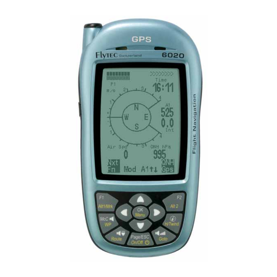
Operating Manual Flytec 6020 6020 GPS Operation Manual Vers.3.05 Flytec AG Ebenaustrasse 18 , CH – 6048 Horw Switzerland Tel. +41 41 349 18 88 – flytec@swissonline.ch - www.flytec.ch - 1 -... -
Page 2: Table Of Contents
Operating Manual Flytec 6020 Table of Contents Table of Contents..........................4 The Instrument ............................. 4 Switching ON and OFF the 6020-GPS ....................5 Keyboard and summary of display screen.................... 5 First steps............................. 9 1.4.1 Prior to the first flight .............................9 1.4.2... - Page 3 Operating Manual Flytec 6020 9.2.2 Stall alarm................................47 Navigation ............................48 9.3.1 Reception quality of GPS ............................48 9.3.2 Accuracy of GPS altitude ............................48 Flight optimisation..........................51 9.4.1 Final glide calculation ............................51 9.4.2 Safety altitude (Alt a. BG) ...........................52 9.4.3 Final Glide calculation over several Waypoints....................52 Flight Memory and IGC File........................
-
Page 4: Table Of Contents
Operating Manual Flytec 6020 1 Table of Contents 1.1 The Instrument SD card slot for future applications jack for Windspeed - sensor Not used on 6020 (charge socket 6030) cover right side safety cord - 4 -... -
Page 5: Switching On And Off The 6020-Gps
Operating Manual Flytec 6020 1.2 Switching ON and OFF the 6020-GPS The instrument is switched-on by pressing the key. In order to avoid unintentional Page/ESC On/Off switching-on, it is necessary upon display prompt „switch on ?? Press Ok“ to confirm by pressing the key. -
Page 6: Main Display Screen
Operating Manual Flytec 6020 Arrow key functions in normal mode Long press.on F1 key Arrow keys F2 key Alt1/Mrk Alti 1013 Alti 1 ↑↓ Alti GPS Alti 2 ↑↓ Alt 2 Set 0 Add Wayp. next↑pr↓ wp HT wind Auto... -
Page 7: Map Screen
Operating Manual Flytec 6020 Map Screen Defined Air Space Waypoint in a Route with cylinder Defined Air Space (not yet available) Waypoint in a Track, flown leg Route with cylinder Scale Digital Variometer Altitude Function of F1 key Function of F2 key Information lines ESC is used to select the Map Mode. -
Page 8: Final Approach Screen
Operating Manual Flytec 6020 Final approach screen Charge state of battery 1 and Number of Satellites battery 2 received by GPS User defined field Current page Exit assistance and Deviation between required L/D Track recommendation to Goal and best glide of the aircraft. -
Page 9: First Steps
Operating Manual Flytec 6020 1.4 First steps 1.4.1 Prior to the first flight page Entry of pilot’s name, type of aircraft and number 10, 11 Selection of recording interval Setting of acoustics Battery check and replacement or repositioning the banks... -
Page 10: User Defined Fields
Operating Manual Flytec 6020 1.5 User defined fields The main screen as well as the final approach screen each show up to 3 pages which are shifted by use of the ► key. Due to this feature it is possible to display nearly all the following measuring data in their correct context. -
Page 11: Menu Sequence
Operating Manual Flytec 6020 By pressing the ► key the cursor moves to the next letter position etc. By using the it is possible to shift between capitals and special characters, or between minuscule and numbers. By use of the key any figure is deleted (rub out). -
Page 12: Display Screens
Operating Manual Flytec 6020 2 Display Screens 2.1 Altimeter and air pressure A barometric altimeter calculates altitude from the present air pressure of the atmosphere. Air pressure will decrease at increasing height. Due to the fact that air may be compressed, the pressure decrease is not linear, but indeed exponential. -
Page 13: Altimeter A2, Relative Altitude
Operating Manual Flytec 6020 Pressing the ▲key will increase the displayed altitude, the ▼ key will decrease altitude. Due to this adjustment the air pressure display will also change. This air pressure value (QNH) is always related to the height at sea level. -
Page 14: Variometer Functions
The response characteristics of the analogue Vario and of climb acoustics can be set within a wide range. In order to simplify the settings, Flytec has determined 5 basic filters which can be set by the Flychart program to particular requirements when using a special command. -
Page 15: Acoustics And Volume Level (Sound)
2.2.3 Acoustics and Volume Level (Sound) The Menu Climb acoustics facilitates the versatile setting possibilities of the Flytec 6020 GPS Vario – Acoustics. This feature enables a rapid and easy adaptation to the pilot’s requirements. By short pressure on the key the volume level will increase each time by 25%. - Page 16 Operating Manual Flytec 6020 damp Dampening The Variometer value is recalculated every 0.2s. In case of rapid Vario changes and setting of quickly increasing tone pitch, this may possibly result between two calculation phases in a quite important modification of tone frequency. The ear perceives this incidence as a kind of fast “piano effect”.
-
Page 17: Speed
All sound effects described here above may be heard in simulation mode. 2.3 Speed The 6020-GPS provides a speed measuring inlet for a wind wheel sensor. This item displays the true flight speed through the air and starts correct measuring above 1 km/h, it is therefore also very convenient for determination of the wind strength at take-off. -
Page 18: Temperature
In this position the 6020-GPS should not have more than 45° deviation from horizontal position so that the antenna points upwards. -
Page 19: Compass And Flight Direction
Because the receiving intensity of the satellite signals is only approx. 1/1000 of mobile radios, any radio equipment and other disruptive factors (like notebooks) should be operated as far away as possible from the 6020-GPS. The number of received satellites is shown on the upper right side of the bar scale. -
Page 20: Waypoints And Coordinates
Waypoints and coordinates A waypoint is any single point on the earth’s surface that you would like to go to. The 6020-GPS can save up to 200 different waypoints. Each waypoint can have up to 16 characters, e.g. In determining the waypoint, it is also necessary “Fiesch Airfield”. - Page 21 The selection of WP’s to be deleted is effected with the ▲ and ▼ keys. Pressing the key (Del WP) enables the deleting function, for data safety the 6020-GPS is asking again: “Delete Waypoint?”. The reply “Yes” or “No” is at choice, but it is also...
- Page 22 AddWp. In response a beep will chime and the momentary coordinates shall be saved in the memory as a waypoint. As name for the waypoint the 6020-GPS uses the letter M (for marker) and after it the actual date and the time of day in UTC.
-
Page 23: Flying Routes
Operating Manual Flytec 6020 2.6.5 Flying Routes A route is an arrangement of various waypoints. The waypoints used on a Route need to be saved in the unit’s memory. Whilst in the Goto-Function the next WP has to be selected each time from a list by prolonged pressing... -
Page 24: The Competition-Route
Deleting a Route You select the route to be deleted with the ▲ or ▼ keys and confirm by pressing the key (Del.Route). For data safety the 6020-GPS inquires once again: (“Delete Route?”) which is to be answered with Yes or No. - Page 25 Route. Independent of what recording interval for storage is used during a standard flight, it is anyway guaranteed that several Tracklog points are saved in the memory of the 6020-GPS at one second intervals when crossing the cylinder circumference.
- Page 26 Operating Manual Flytec 6020 EXIT Cylinder Exit The signal „waypoint reached“ is audible as soon as the start time is reached and the pilot is inside the start cylinder. It will also sound if the start time is positive and the pilot crosses the start cylinder circumference from outside to inside.
- Page 27 Operating Manual Flytec 6020 During a flight the pilot can see on the Info-field display via count-down how many seconds / minutes are left before opening of the Start line. At the same time he can read in the display „Dist to WP“ and “Dist.Cyl” if he is inside or outside of the start cylinder.
-
Page 28: Diff. Bggoal
Operating Manual Flytec 6020 2.6.6.4 Dist to Goal (Total distance to the Goal of a Route) In this field there is displayed during flight of a Route the sum of the legs lying in front of the pilot. The distance is calculated from the current position. Thus he knows at any moment,... -
Page 29: Relocating Thermals
(see position 3). 2.6.10 Air Space - CTR (Restricted areas) On the 6020-GPS up to 150 CTR’s can be entered. The CTR’s may comprise straight lines and arc segments, or also be circles. These sectors appear in the Map Mode. - Page 30 (to the right or to the left) in which these lines should be displayed later. The 6020-GPS instrument draws automatically a line from the recent waypoint to the first one. It is therefore not required to repeat as last waypoint the first one.
-
Page 31: Flight Optimisation
If it is negative, it contains at least a part of head wind and the glide ratio over ground will decrease. The 6020-GPS takes this wind portion in any case into consideration for calculation of the final glide. The Windspeed can be displayed as user field. -
Page 32: Glide Ratio ( = L/D Ratio)
Operating Manual Flytec 6020 2.7.4 Glide ratio ( = L/D ratio) By definition, the glide ratio is calculated by taking the horizontal distance traveled and dividing it by the height which was lost. If instead of the horizontal speed is taken the speed through the air, the error is 2% at glide ratio 5 and just only 0,5% at glide ratio 10. -
Page 33: Display Screen Final Approach
2.7.6 Display screen final approach In order to realise all these data at a glance, the Flytec 6020-GPS provides a specific display screen which shows the pilot in an intuitive mode, if he can reach his goal and in which way he can reach it optimally. - Page 34 Operating Manual Flytec 6020 Alt a BG L/D req 5.7 275m Best glide –exit point 931m over Best glide 8 the goal 681m act. height 956m Act. distance to goal 5.45 km For the example given above the pilot has entered the best glide ratio 8. If he would be precisely on the path of best glide, the wing symbol would be exactly on the horizontal line, and „Alt a.BG“...
-
Page 35: Battery - Management
Operating Manual Flytec 6020 2.8 Battery - Management Two Bargraph scales show the charge state of the batteries. The Flytec 6020 is provided with 2 battery banks with 2 batteries each. Bank 1 must always be loaded. Bank 2 may be kept unloaded. -
Page 36: The Setting Menus
Operating Manual Flytec 6020 3 The Setting Menus Prolonged pressing of the key gives access to the setting mode. With the arrow keys▼ and ▲ one of the menu items is selected and pressing the key gives access to the relevant subdirectory. -
Page 37: Memory Management
Operating Manual Flytec 6020 3.2 Memory Management Delete all Flights Deleting the entire flight memory. This command reformats the flight memory, while all the other settings are not lost. Delete all WP’s & Deleting all WP’s and Routes Routes Formatting Memory Reset of Basic values to factory settings... -
Page 38: Specific Instrument Factory Settings
6020-GPS. The minimum value is 2 seconds, which is in accordance to a recording time of approx. 9 hours. - Page 39 60s is more than 30m. In each case however, the previous flight history with up to 30 recording points is filed in the 6020-GPS memory. With it, and at 10 sec. recording interval, even the last 3 minutes before the start of the filed flight can be noted.
-
Page 40: Logbook And Flight Analysis Page
Operating Manual Flytec 6020 4.1.1 Logbook and Flight Analysis page FLIGHT-ANALYSIS After leaving the Flight-Analysis the flight is saved in the Date: 24.09.04 flight memory. Data and Track of the flight can be viewed Start: 06:19:06 ⇒ on the Flight-Analysis page. Under Main Setup Menu... -
Page 41: Data Transfer
Operating Manual Flytec 6020 4.2 Data transfer In the memory of the 6020-GPS are saved all data entered by the pilot, such as waypoints, Routes, pilot’s name etc., as well as the automatically by the instrument recorded tracklog- points of the flights being performed. Each one of these points contains the time of day, position, GPS-altitude, barometric altitude, as well as the flight speed. -
Page 42: Fightinstrument Option
6020-GPS. In order to be able to write into the 6020-GPS flash memory with a PC, the program “Flasher.exe” is required, which is available in zipped format file under the name of “Flasher.zip”. -
Page 43: Miscellaneous
The numbers appearing in the field on the right side are the instrument’s response. Important: By contrast to the flight data transfer make sure that the 6020-GPS is not switched-on when the connection cable to the PC is plugged. -
Page 44: Simulation
During simulation mode the GPS-Receiver is switched-off and instead of its bar graph the word "Simulation" appears. A simulated flight is well stored into the memory of the 6020-GPS, but its “Digital Signature” is not valid. 7 Disclaimer of Warranty: In rare cases it might happen that the instrument does not provide any data at all or incorrect data. -
Page 45: Landing In Water
Operating Manual Flytec 6020 7.1 Landing in Water In case you are forced to land in water with your 6020-GPS and it may have penetrated the instrument, there is still a chance to save the instrument or at least some of its parts. -
Page 46: Appendix
Operating Manual Flytec 6020 9 Appendix 9.1 Altimeter An altimeter is really a barograph because it doesn’t directly measure altitude, but air pressure. Altitude is calculated from air pressure data. The pressure at sea level is used as zero point altitude for the calculation of absolute altitude (according to the international altitude formula). -
Page 47: Stall Alarm
However, stall speed also depends on the specific weight of the air, meaning: the flight altitude. On the 6020-GPS the stall alarm level is automatically raised with increasing flight altitude, corresponding precisely to Indicated Airspeed. It is unimportant if the pilot has selected True- or Indicated Airspeed for the speed display screen. -
Page 48: Navigation
In particular when mounted on the steering bar of the hang glider, we recommend not to have the instrument fixed under the pilot’s head on the middle of the basis, but indeed sideways. In this position the 6020-GPS should not have more than 45° deviation from horizontal position so that the antenna points upwards. - Page 49 Operating Manual Flytec 6020 Satellite orbit radius =26560km Earth radius =6360km The position is derived from a triangulation. The GPS receiver measures the time of the signals and calculates the distance to the respective satellite by taking into account the speed of light.
- Page 50 This is an explanation of the lower accuracy and the run after or delay of the vertical position. The GPS module of the Flytec instruments does not perform a timed filtering over the horizontal position, but in case of good reception quality it does a filtering over approx. 5 s for the vertical position.
-
Page 51: Flight Optimisation
This speed value has to be calculated from the polar curve and the resulting figure is the speed to fly. Given the fact that the 6020-GPS does not compute with the polar curve, one needs to estimate this „optimal“ speed by himself. -
Page 52: Safety Altitude (Alt A. Bg)
Final Glide calculation over several Waypoints As of the 6020-GPS a new user selectable field „Alt a. Goal“ has been added. This is a pre-calculation, based on best glide ratio, of required altitude above (or below) the last WP of a Route, irrespective of how many WP’s are still in front of the pilot. -
Page 53: Flight Memory And Igc File
Operating Manual Flytec 6020 9.5 Flight Memory and IGC File 9.5.1 Content of IGC Files In the IGC File are saved all important data of a flight in readable format. One can open the IGC File by using any desired Editor. -
Page 54: New Regulations For Record Flights Or Decentralised Competitions (Olc)
Since the evidence of a completed flight depends entirely on the GPS recording, it is important to ensure before take-off that the GPS-receiver indeed receives satellite signals. Therefore please switch-on the 6020-GPS at least a few minutes before take-off so - 54 -... -
Page 55: Evidence Of Flights - Safety Against Manipulation
After completion of a flight, effected automatically or manually, this „Digital Signature“ is calculated autonomously by the 6020-GPS and added to the flight data file as so-called G-record. A correlative remark „Generating Digital Signature“ is displayed in the info field of the instrument.
Need help?
Do you have a question about the 6020 and is the answer not in the manual?
Questions and answers