Table of Contents
Advertisement
Quick Links
Download this manual
See also:
User Manual
Advertisement
Table of Contents

Related Manuals for Flytec 5020


Summary of Contents for Flytec 5020
- Page 1 5020 GPS User Manual V1.14 Flytec AG Ebenaustrasse 18 , CH – 6048 Horw Switzerland Tel. +41 41 349 18 88 – flytec@swissonline.ch - www.flytec.ch Flytec USA 6548 Groveland Airport Road, Groveland, FL 34736, USA +1.352.429.8600 • • http://www.flytec.com info@flytec.com...
- Page 2 Flytec 5020 Technical Manual Flytec USA would like to thank the considerable help from Belinda Boulter editing this manual. If you find any errors, inconsistencies or feel that some sections need better explanation, please email us at info@flytec.com so we can update the manual.
-
Page 3: Quick Start
To switch the 5020 on, press Esc/O and confirm this action by pressing Enter when prompted. To switch the 5020 off, press Esc/O for 3 seconds. The display will inquire “Switch Off??” Press Enter to confirm. After a long flight with short record intervals the calculation of the digital signature can take up to one or two minutes. -
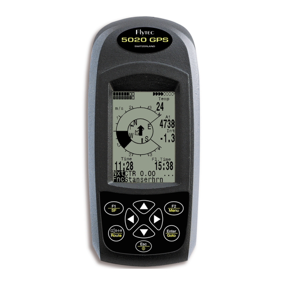
Page 4: Vario Screen
Flytec 5020 Technical Manual Vario Screen Remaining capacity of Number of battery banks 1 and 2 satellites received User selectable field Units for analog vario Bearing to next waypoint Altitude Direction of wind Digital Variometer mode Analog Variometer Digital Variometer... -
Page 5: Final Approach Screen
Flytec 5020 Technical Manual To view the track of a saved flight, press F1 (Shw Map) while viewing the Flight Analysis page (see Section 8, “Flight Memory and Flight Analysis”). This display shows your screen-optimized flight track with scale and waypoints (North is located at the top). You can change the display using the F1, F2, Enter and Esc keys;... -
Page 6: Main Setup Menu
After modifying a value, press Enter to confirm the new setting and move the cursor to the next value, or press Esc to recall the previous setting. At any time it is possible to reset the 5020 to the manufacturer’s tested basic settings in the Basic Settings menu by selecting Init EEPROM. -
Page 7: User Selectable Fields
Flytec 5020 Technical Manual Vario/Spd Delay Turbulence pre-filter 1 to 10; Pre filter = 1 Response delay for analogue vario Delay = 12 (1.2 and speed, range 6 to 40 (0.6 to 4.0 sec) sec) Best L/D Best glide ratio with corresponding L/D = 8.0... -
Page 8: Battery Management
After a long flight it is recommended that the partly used batteries of Bank 2 be moved into Bank 1, and Bank 2 be equipped with new batteries. This will allow the 5020 to completely use up the batteries without the danger of having empty batteries during a flight. -
Page 9: Transferring New Firmware To The 5020
5020. To be able to write to your 5020’s flash memory with a PC, you will need to use an upload utility program named “Flasher.exe,” available from Flytec’s website in zipped form (flasher.zip). -
Page 10: Table Of Contents
Basic Settings..............................6 User Selectable Fields ............................7 Battery Management............................8 1.10 Data Exchange via PC............................8 1.11 Transferring New Firmware to the 5020......................9 Technical Data............................9 Warranty and Liability .........................9 Contents..............................9 Analog Vario ............................12 Altimeter and Air Pressure..........................12 Acoustics and Volume Level........................... - Page 11 Optional Software Packages .......................... 29 10.5 NMEA Data Output ............................29 10.6 Data Transfer ..............................29 10.7 Data Exchange via PC............................ 29 10.8 Transferring New Firmware to the 5020......................30 Landing in Water..........................31 Warranty and Liability ........................31 - 11 - © Flytec USA...
-
Page 12: Analog Vario
Altimeter and Air Pressure The 5020 tracks and can display 4 different altitudes and the QNH. A1 is shown on the right side of the vario screen and A1, A2, A3, FL and QNH can be displayed in the user-selectable fields. -
Page 13: Acoustics And Volume Level
Flytec 5020 Technical Manual Acoustics and Volume Level Each time you briefly press 0-I-II, the volume level increases by 25%. The adjustable sound levels are: 0 - 25% - 50% - 75% - 100%. Each time you press 0-I-II, the chosen volume level will briefly appear in the display. -
Page 14: Digital Vario
3 Airspeed The 5020 has an input for a vane wheel speed sensor. It shows the true air speed (TAS) and begins to make correct measurements above 1 mph (1 km/h). The vane wheel sensor is also well suited for determining the wind strength at take-off. -
Page 15: Stall Alarm
However, if the signal to the almanac memory is disrupted completely or the 5020 is taken more than 125 miles from the last reception point, then the almanac has to be re- established. In this case it can take ten minutes (or more) to determine the new position. When the 5020 is turned off, power is still supplied to the almanac’s memory. -
Page 16: Compass And Flight Direction
Track field. When circling in a thermal the compass rose appears to turn; in reality the needle does not move, the 5020 moves around the rose along with the aircraft. Track and Bearing... -
Page 17: Head, Cross And Tail Winds - The Wind Component
If it is negative then you are flying with a head wind and your glide ratio will worsen. The Flytec 5020 takes the wind into consideration when calculating final glide. To learn how to find the correct angle between your destination and the wind when a strong cross wind is present, please refer to Section 7.9, “The Goto Function.”... -
Page 18: Editing Waypoints
To delete a waypoint, select it with keys from the waypoint list and press F2 (Del WP). To be on the safe side the 5020 will ask for confirmation by showing, “Delete Waypoint?” Use the keys to switch from “No” to “Yes”, and press Enter. The deletion process can be stopped by Esc. -
Page 19: Current Coordinate Indicator
4.8.4 Current Coordinate Indicator Provided the 5020 is receiving a GPS signal, you can view your actual position can in the unit’s Information Lines by pressing Enter. After twenty seconds the display will automatically revert to the previous content. This function is useful after landing to relay your location to a person coming to retrieve you. -
Page 20: Flying Routes
4.10 Flying Routes A route is a sequence of waypoints. The waypoints used on a route must first be entered into the 5020’s waypoint list. In contrast to the Goto function where you must choose the next waypoint from a long list by pressing and holding Goto, you can advance or move back to a previous waypoint in a route with the ... -
Page 21: Routes: Create - Delete - Alter
Flytec 5020 Technical Manual Direction arrow to second next waypoint: In the middle of the compass rose, a thick black arrow points to the next waypoint. If there is more than one waypoint remaining in an active route there will be a second, transparent, pointer under the black pointer, showing the direction of the second waypoint (see figure). -
Page 22: Deleting A Route
Select the route to be deleted from the route list using the keys and press F2 (Del Rte). To be on the safe side the Flytec 5020 will inquire “Delete Route?” To proceed with deleting the route, change the blinking “No” to “Yes” with the keys and press Enter. It is not possible to delete the Competition Route. -
Page 23: Competition Route: Set - Alter - Delete
PC. 4.14 Flying a Competition Route Because the GPS receiver in the 5020 confirms its position every second, it only takes 1 second for you to be alerted that you have crossed a cylinder circumference. When this happens the 5020 will alert you with an unmistakable tone lasting 2 seconds and will automatically transition to the next waypoint in the route. -
Page 24: Final Approach Screen And Final Glide Calculations
Flytec 5020 Technical Manual “Next ↑ pr ↓ wp” function. Here you can toggle back and forth between previous and next waypoint with the keys. When flying with an active Competition Route it is possible to select additional waypoints by pressing and holding Goto. -
Page 25: Relocating Thermals
F L I G H T - A N A L Y S I S you to specially activate flight recording; each flight is automatically saved. The flight recording system used in the Flytec 5020 records D a t e : 2 4 . 0 9 . 0 4... -
Page 26: User Selectable Fields
F2 (Rec Sig). Note: To insure a valid recording, make certain that the 5020 GPS status shows at least 4 satellites received before starting a flight. 6 User Selectable Fields On the Vario Page and the Final Glide Page there are a total of 3 user selectable fields that can be assigned as you wish. -
Page 27: Flight Time
Flight Analysis”). The flight time can be displayed in a user-selectable field (Fl Time). The 5020 will also automatically recognize the end of your flight. You can set the 5020 to end a flight recording manually or automatically under Basic Settings/Recording Mode . -
Page 28: Battery Management
Battery Management The 5020 has 2 bar scales that indicate the remaining capacity of the batteries. There are 2 banks of 2 AA batteries each. Battery Bank 2 may be empty, but Bank 1 must always be equipped (however it is recommended that Bank 2 be equipped as well). -
Page 29: Optional Software Packages
Important: the 5020 must first be switched on before plugging in the connection cable to the unit and the computer. The 5020 comes complete with a serial PC interface data cable (9 pol Sub D plug). Data transfer between the 5020 and a PC can occur in both directions. The connection occurs with: 57,600 baud;... -
Page 30: Transferring New Firmware To The 5020
To be able to write to the 5020’s flash memory with a PC, you must use an upload utility program named flasher.exe that is available in zipped form (flasher.zip). You must also obtain the actual firmware to be uploaded. -
Page 31: Landing In Water
WARNING: In very rare cases it can happen that a flight instrument does not provide any data at all or the data is incorrect. Flytec will not be held responsible for any damage claims arising from a malfunctioning unit. Responsibility for ensuring the safe execution of his/her flights lies with the pilot alone.
Need help?
Do you have a question about the 5020 and is the answer not in the manual?
Questions and answers