Table of Contents
Advertisement
Quick Links
Advertisement
Table of Contents

Subscribe to Our Youtube Channel
Related Manuals for Lantronix Series 1000


Summary of Contents for Lantronix Series 1000
- Page 1 Series 1000 User Manual 13 July 2001...
- Page 2 Lightwave Communications, Inc. 100 Washington Street Milford, CT 06460 USA (800) 871-9838 • (203) 878-9838 • Fax: (203) 874-0157 Email: info@lightwavecom.com • Internet: www.lightwavecom.com LCI Asia/Pacific postal address: P.O. Box 19 GlenIris VIC 3146 Australia delivery address: 16 Network Drive Port Melbourne VIC 3207 Australia +61 3 9646 1144 •...
-
Page 3: Table Of Contents
8.7 Password Commands................27 Appendix A – Control Card Settings ..............29 Appendix B – Pinouts .....................31 Appendix C – Sample Matrix-Hub Session............36 Matrix-Hub Series 1000 User Manual 13 July 2001 Copyright 1999-2000 Lightwave Communications, Inc. 100 Washington Street, Milford, Ct, 06460, USA All rights reserved. -
Page 4: Matrix-Hub System Overview
1.0 Matrix-Hub System Overview The Matrix-Hub Series 1000 is a matrix switch for the entire desktop. The switch may route video, keyboard/mouse, and serial connections using an integrated user interface. Each type of connection may be individually managed or may be integrated to operate with one or both of the other connection types. -
Page 5: Matrix-Hub Components
(see section 7.0, Electroluminescent Display). The Series 1000 has redundant power supplies with separate AC inputs. Each power supply is a set of two individual power supplies that provides separate +5VDC and –5VDC. In ordinary operation, the two power supply sets share the electrical current load equally. - Page 6 Power Supplies – Series 1000 Chassis Front pair provides +5 VDC Rear pair provides –5 VDC Every chassis has three switch cards. Each switch card handles one element of video signals (red, green, or blue), and two of the switch cards also handle keyboard and mouse signals (serial signals are switched internally by the serial cards and are not routed through the switch cards).
-
Page 7: Adding And Removing Cards
Back of Matrix-Hub Series 1000 Chassis with All Cards 2.1 Adding and Removing Cards Matrix-Hub cards may be purchased separately at any time to expand the capacity or change the functionality of an existing unit. The user may add or remove cards in the field quite easily, allowing for great flexibility of existing systems. - Page 8 All cards for the Series 1000 have metal key tabs protruding along their inside edge near the backplane connectors. These tabs prevent the insertion of keyboard/mouse, serial, or control cards into slots designated for video or switch cards.
-
Page 9: Replacing Failed Power Supplies
Key Tabs – Series 1000 Cards left – keyboard/mouse input & output, serial input & output, control right – matrix switch, video input & output 2.2 Replacing Failed Power Supplies If a power supply fails in a unit, it may be replaced in the field if necessary. Be sure the failure is not due to a damaged power cord or a faulty outlet. -
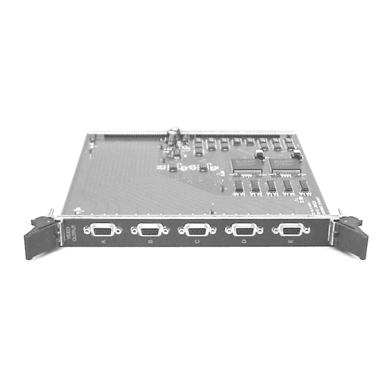
Page 10: Video Cards
3.0 Video Cards Video Input, Part Number 400.100.1001 Video Output, Part Number 400.100.1002 Video input cards (part number 400.100.1001) and video output cards (part number 400.100.1002) are located in the four slots immediately surrounding the switch cards, two to each side. The input cards are located to the left, while output cards are located to the right. - Page 11 Video Port Numbering Scheme Each card has five HD15 female connectors. From the connectors, the input card routes red, green, and blue video signals, as well as horizontal and vertical sync and three monitor ID lines to the switch cards. The switch cards then pass the signals selected output card connector(s).
-
Page 12: Keyboard/Mouse Cards
4.0 Keyboard/Mouse Cards PS/2 Input Card, Part Number 400.100.2001 PS/2 Output Card, Part Number 400.100.2002 RJ 45 Extender Input Card, Part Number 400.000.2009... - Page 13 RJ 45 Extender Output Card, Part Number 400.000.2010 The keyboard/mouse input cards (PS/2: part number 400.100.2001 or RJ 45: part number 400.000.2009) and keyboard/mouse output cards (PS/2: part number 400.100.2002 or RJ 45: part number 400.000.2010) are located in the four slots immediately outboard from the video cards, two to each side.
- Page 14 PS/2 Keyboard/Mouse Port Numbering Scheme RJ 45 Keyboard/Mouse Port Numbering Scheme There are two types of keyboard/mouse cards: PS/2 and RJ 45 Extender. The PS/2 cards are designed to connect directly CPUs, keyboards, and mice to the Matrix-Hub using PS/2 cables. The RJ 45 Extender cards are designed to work with Lightwave’s PS/2 Keyboard/Mouse Cat5 Extender or VDEs, either separately or together.
- Page 15 Extender card. Contact Lightwave for more information regarding the use of the Matrix-Hub with VDEs and CAT5 Keyboard/Mouse Extenders.
-
Page 16: Serial Cards
5.0 Serial Cards Input Card, Part Number 400.100.3001 Output Card, Part Number 400.100.3002 The serial input cards (part number 400.100.3001) and serial output cards (part number 400.100.3002) are located in the four slots immediately to the left of the control card. Unlike other card types, any combination of inputs and outputs may be mixed in the four serial slots so long as the inputs are to the left and the outputs are to the right. - Page 17 Numbering Scheme for Two Input Cards and Two Output Cards Numbering Scheme for One Input Card and Three Output Cards...
- Page 18 Numbering Scheme for Three Input Cards and One Output Card The serial cards support both RS-232 and RS-422 connections through DB9 connectors. The serial protocol is determined by the command used at the control card to make the connection (see section 8.4.1, Serial Connections). The serial cards will also support the stereo emi tter used with 3D visualization.
-
Page 19: Switch And Control Cards
6.0 Switch and Control Cards Switch Card, Part Number 400.100.1003 Control Card, Part Number 400.100.1004 Three switch cards and one control card are included in each Matrix-Hub chassis. The switch cards are located in the three slots between the video input cards and the video output cards. - Page 20 The control card (part number 400.100.1004) coordinates and reports actions within the Matrix-Hub. It provides the user interfaces, initiates connections between cards, and stores macros and other connectivity shortcuts in memory. There are two DB9 connectors on the control card; one is male, while the other is female.
-
Page 21: Electroluminescent Display
7.0 Electroluminescent Display Electroluminescent Display in Screen Saver Mode The electroluminescent (EL) display allows the user to access the Matrix-Hub’s internal diagnostics and active connection list through the front panel. The two buttons located immediately below the display control the EL display. When not in use, the display goes into a screen saver mode and displays a moving Matrix- Hub logo. - Page 22 Electroluminescent Display Showing Sample Connections List – For video cards: input port 4 is connected to output port 1 and input port 3 is connected to output port 3; for keyboard/mouse cards: input port 4 is connected to output port 1 and input port 3 is connected to output port 3. Pressing the left button displays the active connection list.
- Page 23 Electroluminescent Display Showing Sample Installed Cards List – Chassis in this example has two input cards of each type, but only one output card of each type. Pressing the right button displays the installed cards list. The cards are listed in the same order they are mounted in the chassis.
-
Page 24: User Interface
(i.e., an ASCII terminal, a PC running a terminal program, a network interface, etc.). Internal to the Matrix-Hub Series 1000, each card type is divided into separate chassis. Video cards are chassis 1, keyboard/mouse cards are chassis 2, and serial cards are chassis 3. -
Page 25: Help Menu
access, which only allows predefined connections (i.e., macros and entities) to be made. Level two access is indicated by the following prompt: MatrixHub$ See sections 8.7 Passwords, 8.5 Entity Commands, and 8.6 Macro Commands for more information regarding the use of the two password levels. 8.2 Help Menu The help screen listing all the available Matrix-Hub commands may be reached by entering H or ?. -
Page 26: Connection Commands
degrees Celsius. Typical values range from room temperature to around 100 F (38 C), depending on the number of active connections and the physical installation of the chassis. The CS command displays a list of active connections for the specified internal chassis ID. -
Page 27: Serial Connections
a dash. Output ports may be individually disconnected from the broadcast using the disconnect command The D, or disconnect, command will disconnect the specified ports from one another. This command may also be used to disconnect all the connections in the Matrix-Hub or all connections in an internal chassis. -
Page 28: Entity Commands
8.5 Entity Commands Entities allow the user to define a group of input or output ports that should be connected together. This allows resources to be switched as a group to an end user. Inputs are grouped together in source entities, while outputs are grouped together in destination entities. -
Page 29: Macro Commands
Entities may be connected to one another using the C command in the form C SOURCE_ENTITY DESTINATION_ENTITY or may be disconnected with the D command using the same syntax. If an entity is connected to another entity, and is then specified in a new connect command, then that entity will be switched to the new connection. -
Page 30: Autoexec Macro
macros that are defined in Matrix-Hub memory. If a macro name is specified at the command line, the commands defined for the macro will be listed. The MN command creates a new macro. The name of the new macro must follow the command or an error message will be returned and a new macro will not be created. - Page 31 while the level two password is mh2. These passwords should be deleted as soon as possible to prevent unauthorized access to the Matrix-Hub. List password commands List number of defined passwords Delete a password Create a password The PH command lists the commands that are used only with passwords. The PL command lists the number of passwords defined on the Matrix-Hub.
-
Page 32: Appendix A - Control Card Settings
Appendix A - Control Card Settings There are three DIP switches mounted on the surface of the control card that allow the user to change the control card parameters. One DIP switch (SW1) is reserved for system use and should not be changed. The other switches (SW2 and SW3) change the control card IN port baud rate and user interface options. - Page 33 SW1 – System Use (do not change) Switch Position SW2 – IN Port Baud Rate Switch Position Baud Rate 19,200 9600* 4800 2400 *Factory default setting SW3 – User Interface Options Switch Position Display temperature in F Display temperature in C Do not echo characters Echo Characters Do not send error...
-
Page 34: Appendix B - Pinouts
Appendix B – Pinouts Video Input Video Output HD15F HD15F Analog Analog Green Inputs Outputs Blue Horizontal Sync Inputs Outputs Vertical Sync Monitor ID 0 Monitor ID 1 Outptus Inputs Monitor ID 3 Red Return Green Return Blue Return Sync Return HD15 Video Pinout... - Page 35 Control Card IN Port Pinouts DB9 Female Connector SIGNAL NAME DESCRIPTION INPUT/OUTPUT Receive Data Output Transmit Data Input Data Terminal Ready Input Signal Ground Data Set Ready Output Request to Send Input Clear to Send Output...
- Page 36 Serial Input Port Pinouts DB9 Female Connector RS-232 SIGNAL NAME DESCRIPTION INPUT/OUTPUT Carrier Detect Output Receive Data Output Transmit Data Input Data Terminal Ready Input Signal Ground Data Set Ready Output Request to Send Input Clear to Send Output Ring indicator Output RS-422 SIGNAL NAME...
- Page 37 Serial Output Port Pinouts DB9 Male Connector RS-232 SIGNAL NAME DESCRIPTION INPUT/OUTPUT Carrier Detect Input Receive Data Input Transmit Data Output Data Terminal Ready Output Signal Ground Data Set Ready Input Request to Send Output Clear to Send Input Ring Indicator Input RS-422 SIGNAL NAME...
- Page 38 RS-422 to DB9 Conversion Pinouts Matrix-Hub Matrix-Hub Serial Input Serial Output RS-232 RS-232 100 Washington Street, Milford CT 06460 800 871-9838 * Fax 203 874-0157 * www.lightwavecom.com Title: RS-232 mode Pinouts for Serial Input / Output Part Number Drawing Number Matrix-Hub Serial Size: System:...
-
Page 39: Appendix C - Sample Matrix-Hub Session
Appendix C – Sample Matrix -Hub Session The following text is a sample session printed from a terminal program log file. It contains examples of the use of Matrix-Hub commands in the two different password levels. Lightwave Communications Matrix Hub Console Copyright 1998 Version: 1.02 ...please wait for initialization... - Page 40 1PT 88ßF 1PT 91ßF 1PT 89ßF success MatrixHub# cs 1 success MatrixHub# cs 2 success MatrixHub# cs 3 success MatrixHub# connect 1 1 1 1C1,1 success MatrixHub# cs 1 1 TO success MatrixHub# connect 2 1 1 2C1,1 success MatrixHub# cs 2 1 TO success MatrixHub# connect 3 1 1...
- Page 41 2C1,1 3C6,6 3C101,101 success MatrixHub# cs 1 1 TO 1, 10 success MatrixHub# cs 2 1 TO success MatrixHub# cs 3 101 TO 101 6 TO success MatrixHub# clear Are you sure (y/n):Y success MatrixHub# restore No connections to restore MatrixHub# b 1 1 1-10 1B1,1,2,3,4,5,6,7,8,9,10 success...
- Page 42 Chassis: port: Chassis: port: Chassis: port: success MatrixHub# en conf_room_1 dst Enter entity item (chassis-id, port #): 1,1, Enter entity item (chassis-id, port #): 2,1 Enter entity item (chassis-id, port #): 3,1 Enter entity item (chassis-id, port #): success MatrixHub# el Entity List ----------- Entity type, name: SRC, ONYX2...
- Page 43 Enter entity item (chassis-id, port #): 1,2 Enter entity item (chassis-id, port #): 2,2 Enter entity item (chassis-id, port #): 3,2 Enter entity item (chassis-id, port #): success MatrixHub# el Entity List ----------- Entity type, name: SRC, ONYX2 Entity type, name: DST, CONF_ROOM_1 Entity type, name: SRC, OCTANE Entity type, name: DST, ENG_LAB success...
- Page 44 MatrixHub# es Entity Status ------------- ONYX2 CONF_ROOM_1 SOFTW_LAB success MatrixHub# cs 1 1 TO 3 TO success MatrixHub# cs 2 1 TO 3 TO success MatrixHub# cs 3 1 TO 3 TO success MatrixHub# c onyx2 softw_lab 1B1,3 2B1,3 3B1,3 success MatrixHub# es Entity Status...
- Page 45 3 TO success MatrixHub# cs 2 1 TO 3 TO success MatrixHub# cs 3 1 TO 3 TO 110 TO 110 success MatrixHub# clear Are you sure (y/n):Y success MatrixHub# es Entity Status ------------- success MatrixHub# mh +===================== MaxtriX-Hub System Help ============================+ |- Macro Commands ---------------------------------------------------------| - Macro Help MR <macro>...
- Page 46 2B3,1 3B3,1 (mr SETUP_1) END MACRO Macro completed MatrixHub# es Entity Status ------------- ONYX2 ENG_LAB OCTANE SOFTW_LAB CONF_ROOM_1 success MatrixHub# cs 1 1 TO 2 TO 3 TO success MatrixHub# cs 2 1 TO 2 TO 3 TO success MatrixHub# cs 3 1 TO 2 TO 3 TO...
- Page 47 success MatrixHub# cs 2 1 TO 3 TO success MatrixHub# cs 3 1 TO 3 TO success MatrixHub# mr setup_3 (mr SETUP_3) 1B1,1 2B1,1 3B1,1 (mr SETUP_3) 1B2,2 2B2,2 3B2,2 (mr SETUP_3) 1B3,3 2B3,3 3B3,3 (mr SETUP_3) END MACRO Macro completed MatrixHub# es Entity Status -------------...
- Page 48 Cannot delete current password MatrixHub# logoff success Enter password: *** MatrixHub$ c 1 1 1 Command not allowed for current access level MatrixHub$ b 1 1 1-10 Command not allowed for current access level MatrixHub$ d 1 1 1 Command not allowed for current access level MatrixHub$ clear Command not allowed for current access level MatrixHub$ restore...
- Page 49 Command not allowed for current access level MatrixHub$ ph Command not allowed for current access level MatrixHub$ pl Command not allowed for current access level MatrixHub$ pd Command not allowed for current access level MatrixHub$ pn 1 Command not allowed for current access level MatrixHub$ lo success Enter password:...
Need help?
Do you have a question about the Series 1000 and is the answer not in the manual?
Questions and answers