
Subscribe to Our Youtube Channel
Related Manuals for Jet JML-1014VS


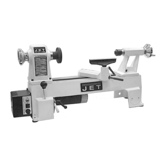
Summary of Contents for Jet JML-1014VS
- Page 1 OWNER’S MANUAL JML-1014VS Mini Lathe WMH TOOL GROUP 2420 Vantage Drive Elgin, IL 60123 Ph: 888-804-7129 Fax: 800-274-6840 ▪ E-mail: jet@wmhtoolgroup.com M-08351VS 8/03 Copyright © WMH Tool Group www.wmhtoolgroup.com...
-
Page 2: Warranty And Service
This manual has been prepared for the owner and operators of a JET Model 1014VS Variable Speed Mini Lathe. Its purpose, aside from proper machine operation, is to promote safety through the use of accepted operating and maintenance procedures. To obtain maximum life and efficiency from your lathe, and to aid in using the machine safely, read this manual thoroughly and follow all instructions carefully. - Page 3 WARNING For your own safety, read this instruction manual before operating the lathe. Do not wear gloves, necktie, or loose clothing. Tighten all locks before operating. Rotate the workpiece by hand before applying power. Rough out the workpiece before installing on the faceplate. Do not mount a split workpiece or one containing a knot.
- Page 4 Use recommended accessories. Consult the owner’s manual for recommended accessories. The use of improper accessories may cause a risk of injury. Never stand on a tool. Serious injury could occur if the tool is tipped or if the cutting tool is unintentionally contacted.
-
Page 5: Electrical Requirements
Electrical Requirements In the event of a malfunction or breakdown, grounding provides a path of least resistance for electric current to reduce the risk of electric shock. This tool is equipped with an electric cord having an equipment-grounding conductor and a grounding plug. The plug must be plugged into a matching outlet that is properly installed and grounded in accordance with all local codes and ordinances. - Page 6 Motor......................1/2 HP, 1Ph, 115V only Overall Dimensions (in.) L x W x H............28-1/8 x 10-1/4 x 14-1/8 Net Weight (lbs. – approx.) ....................... 69 Optional Accessories Available from JET Chisels 5 Piece Mini Set ........................709163 3 Piece Pen Turning Set ....................709160...
-
Page 7: Operation
Receiving 1. Remove contents from the shipping box. 2. Inspect contents for shipping damage and report damage, if any, to your distributor. 3. Be sure to keep the box and packing material should you need to pack the lathe for moving. 4. - Page 8 The tailstock spindle is hollow. This can be useful for inserting a long bit to drill a hole in the center of a workpiece on the faceplate. The clamping device on the tailstock has been factory adjusted; however if further adjustment should be needed, slide the tailstock off the end of the bed, and tighten or loosen the nut (D, Fig.
-
Page 9: Adjusting The Tool Rest
Knockout Rod (A, Fig. 7) - slides into the headstock to tap the spur center free. Stored in the hole in the base below the headstock. NOTE: Always catch the spur center with your other hand as it falls, to prevent damage to the tip. Tool Rest (Fig. -
Page 10: Variable Speed Control
Variable Speed Control The variable speed control box contains the electrical connections to the motor, and has three external controls. WARNING Always set the speed control knob to its lowest setting before starting lathe. Never start a workpiece at maximum speed. Power Switch (A, Fig. -
Page 11: Belt Replacement
3. Loosen the motor plate lock handle (A, Fig. 12). Lift up on the motor plate handle (B, Fig. 12) to take tension off the belt. 4. Move the belt (B, Fig. 10) to the desired pulley groove according to the speed chart found on the inside of the headstock access door. -
Page 12: Maintenance
Removing and Installing the Live Center 1. Loosen tailstock lock handle (B, Fig. 13). 2. Turn the tailstock handwheel (A, Fig. 13) counter-clockwise until the live center (C, Fig. 13) ejects from the spindle. NOTE: Catch the live center in your other hand as it falls, to prevent damage to the tip. - Page 13 Parts Breakdown for the JML-1014VS Mini Lathe...
- Page 14 Parts List for JML-1014VS Mini Lathe Index Part Description Size Qty. 1..JML-1W ........White Headstock..............1 2..JML-2........Faceplate ..........3”........ 1 3..JML-3........Spur Center .......... MT2......1 ....JML-3A ........Center Point for Spur Center (not shown) ........1 4..JML-4........Spindle..........8 TPI ......1 5..JML-5........Key ............
- Page 15 Parts List for JML-1014VS Mini Lathe (continued) Index Part Description Size Qty.....708331........Live Center Assembly (not shown) ........... 1 49 ..JML-55........Tailstock Spindle..............1 50 ..JML-56........Lead screw................1 51 ..JML-57........E-Ring..................1 52 ..JML-58........Eccentric Rod................1 53 ..JML-59........Stud ..................1 54 ..JML-60W ........White Tailstock ........
- Page 16 WMH TOOL GROUP 2420 Vantage Drive Elgin, IL 60123 Ph: 888-804-7129 Fax: 800-274-6840 ▪ E-mail: jet@wmhtoolgroup.com www.wmhtoolgroup.com...
Need help?
Do you have a question about the JML-1014VS and is the answer not in the manual?
Questions and answers