
Related Manuals for Jet JML-1014


Summary of Contents for Jet JML-1014
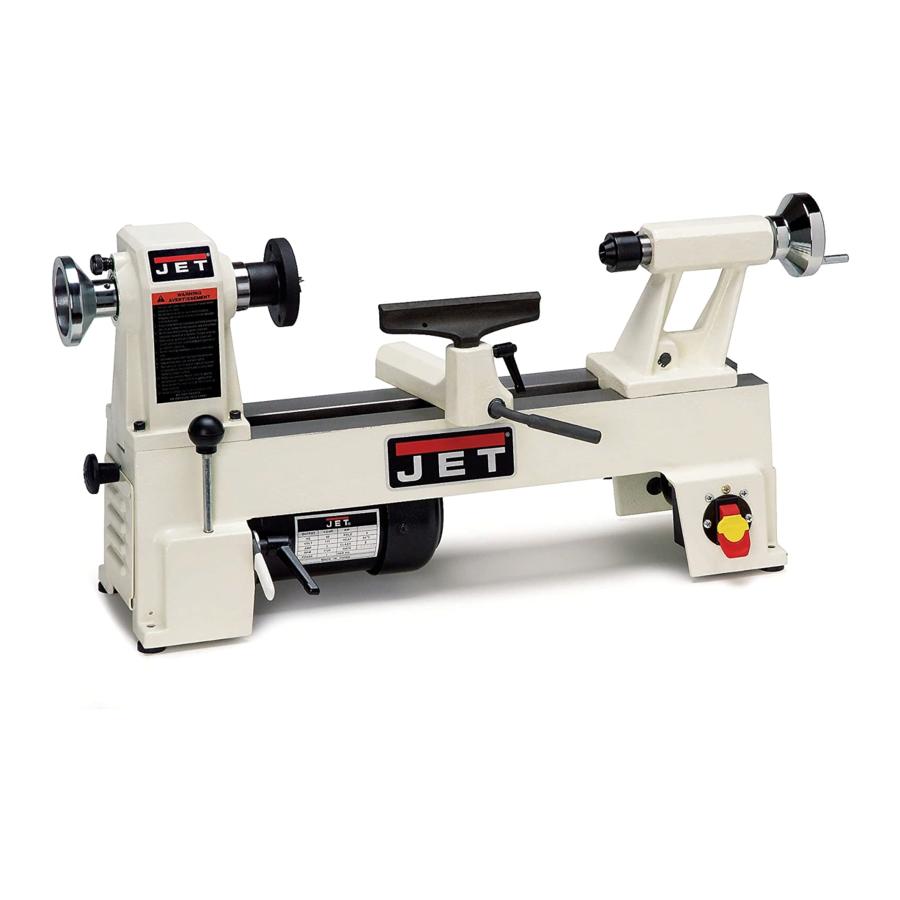
- Page 1 OWNER’S MANUAL JML-1014 Mini Lathe JET EQUIPMENT & TOOLS, INC. A WMH Company www.jettools.com P.O. BOX 1349 Auburn, WA 98071-1349 e-mail jet@jettools.com 253-351-6000 Fax 800-274-6840 M-708351 1-00...
-
Page 2: Replacement Parts
2-YEAR LIMITED WARRANTY REPLACEMENT PARTS Replacement parts for this tool are available directly form JET Equipment & Tools. To place an order, call 1-800-274-6848. Please have the following information ready: 1. Visa, MasterCard, or Discover Card number 2. Expiration date 3. - Page 3 For your own safety, read this instruction manual before operating the lathe. Do not wear gloves, necktie, or loose clothing. Rotate the workpiece by hand before applying power. Rough out the workpiece before installing on the faceplate. Do not mount a split workpiece or one containing a knot.
- Page 4 • ALWAYS USE SAFETY GLASSES. Also use face or dust masks if the cutting operation is dusty. Everyday eyeglasses only have impact resistant lenses, they are NOT safety glasses. • SECURE WORK. Use clamps or a vise to hold the work when it’s practical. It’s safer than using your hand and it frees both hands to operate the tool.
-
Page 5: Electrical Requirements
Electrical Requirements In the event of a malfunction or breakdown, grounding provides a path of least resistance for electric current to reduce the risk of electric shock. This tool is equipped with an electric cord having an equipment-grounding conductor and a grounding plug. The plug must be plugged into a matching outlet that is properly installed and grounded in accordance with all local codes and ordinances. -
Page 6: Specifications
Specifications: JML-1014 Stock Number ... 708351 Swing Over Bed (In.)... 10 Swing Over Tool Rest Base (In.) ... 7 1/2 Working Distance Between Centers (In.)... 14 Number of Speeds ... 6 Range of Speeds (RPM)...500, 840, 1240, 1800, 2630, 3975 Headstock Spindle Threads (T.P.I.)... -
Page 7: Contents Of The Shipping Carton
1 - Owner's manual 1 - Warranty card Assembly The JML-1014 is fully assembled and comes ready to use right out of the box. However, it is a good practice to thoroughly check the machine for loose fasteners, handles, etc. before use. - Page 8 Nomenclature and Use Spur Center (A, Fig. 2) - locks into headstock and holds the workpiece during spindle turning. Face Plate (A, Fig. 3) - attaches to headstock and is used in face plate turning operations. Drift Rod (A, Fig. 4) - slides into the headstock to tap the spur center free.
-
Page 9: Changing Spindle Speeds
Changing Spindle Speeds 1. Disconnect the machine from the power source (unplug). 2. Open the access doors at the left side of the base (A, Fig. 6), and at the back side of the headstock (A, Fig. 7). 3. Loosen the motor plate lock handle (A, Fig. 8). - Page 10 7. Insert the spindle into the spindle pulley aligning the key. 8. Thread the handwheel onto the spindle leaving a little space between the handwheel and headstock. Tighten set screws. 9. Center the spindle pulley and tighten set screw. 10. Wrap the belt around the motor pulley (lower).
- Page 11 Parts List for the JML-1014 Mini Lathe Index Part 1 ... JML-1...Headstock ..1 ... JML-1W ...White Headstock ..1 2 ... JML-2...Faceplate ...3” ... 1 3 ... JML-3...Spur Center...MT2 ... 1 ... JML-3A ...Center Point for Spur Center (not shown) ..1 4 ...
- Page 12 40... JML-40...Stud ..1 41... JML-41...Tool Rest Body..1 ... JML-41W ...White Tool Rest Body ..1 42... JML-42...Tool Rest...6” ... 1 43... JML-43...Bolt ..1 44... JML-44...Clamp ..2 45... JML-45...Stud ..1 46...
Need help?
Do you have a question about the JML-1014 and is the answer not in the manual?
Questions and answers