Table of Contents
Advertisement
Quick Links
Download this manual
See also:
User Manual
CL1000
LCD Console
Quick Start Guide
© Copyright 2014 ATEN
®
International Co., Ltd.
ATEN and the ATEN logo are trademarks of ATEN International Co., Ltd. All rights reserved. All
other trademarks are the property of their respective owners.
This product is RoHS compliant.
Part No. PAPE-1223-372G
Printing Date: 11/2014
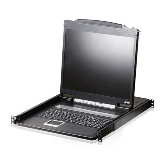
CL1000 LCD Console Quick Start Guide
Hardware Review
A
Front View
1. Handle
2. Slide Release
3. LCD Display
4. LCD Controls
5. Keyboard
6. Touchpad
7. Power LED
8. Rack Mounting Brackets
9. Lock LEDs
10. Reset Switch
11. LED Illumination light
Rear View
1. Power Socket
2. Power Switch
3. KVM Port
System Requirements
Switches and Computers
• The CL1000 supports most KVM switches that have PS/2 console
port connectors.
Guide de mise en route de la console LCD CL1000
Description de l'appareil
A
Vue avant
1. Poignée
2. Bouton coulissant d'ouverture
3. Écran LCD
4. Commandes LCD
5. Clavier
6. Pavé tactile
7. Voyant d'alimentation
8. Supports de fixation pour montage sur rack
9. Voyants de verrouillage
10. Bouton de réinitialisation
11. Eclairage LED
Vue arrière
1. Prise d'alimentation
2. Bouton de mise sous/hors tension
3
Port KVM
Confi guration système
Commutateurs et ordinateurs
• Le CL1000 prend en charge la plupart des commutateurs KVM
disposant de connecteurs de port de console PS/2.
CL1000 LCDKonsole Kurzanleitung
Hardwareübersicht
A
Vorderseitige Ansicht
1. Griff
2. Ausziehentriegelung
3. LCDDisplay
4. LCDBedienelemente
5. Tastatur
6. Touchpad
7. LEDBetriebsanzeige
8. Arretierungen für RackMontage
9. VerriegelungsLEDs
10. Schalter zum Zurücksetzen
11. LED-Beleuchtung
Rückseitige Ansicht
1. Netzeingangsbuchse
2. Netzschalter
3. KVMPort
Systemvoraussetzungen
Switches und Computer
• Der CL1000 unterstützt die meisten KVMSwitches mit
PS/2Konsolportanschlüsse
Consola con pantalla LCD CL1000 Guía rápida
Presentación del hardware
A
Vista frontal
1. Asa
2. Desbloqueo retráctil
3. Pantalla LCD
4. Controles LCD
5. Teclado
6
Panel táctil
7. Indicador LED de alimentación
8. Muescas para montaje en rack
9. Indicadores LED de bloqueo
10. Interruptor de reseteo
11. Iluminacion LED
Vista posterior
1. Entrada de alimentación
2. Interruptor de alimentación
3. Puerto KVM
Requisitos del sistema
Conmutadores y ordenadores
• El CL1000 admite la mayoría de los conmutadores KVM que
disponen de conectores de puerto de consola PS/2.
A
Hardware Review
Front View
2
3
Press the Exit/Light pushbutton
EXIT I LIGHT
for two seconds to turn the
LED light ON or Off. (Default: On)
11
5
6
9
7
8
Rear View
1
2
3
• The integrated LCD monitor's maximum resolution is 1280 x
1024 @75Hz. Make sure that none of the resolution settings of
the connected computers exceed the LCD monitor's maximum
resolution.
Hardware Installation
B
Standard Rack Mounting
A standard rack mount kit is provided with your CL1000. The kit
enables the switch to be mounted in rack with a depth of 42-72 cm.
B-1
1. While one person positions the switch in the rack and holds it in
place, the second person loosely screws the front brackets to the
rack.
B-2
2. While the fi rst person still holds the switch in place, the second
person slides the L brackets into the switch's side mounting
brackets from the rear until the bracket fl anges contact the rack,
then screws the L brackets to the rack.
B-3
3. After the L brackets have been secured, tighten the front bracket
screws.
• La résolution maximale de l'écran LCD intégré est de 1280 x
1024, à 75 Hz. Vérifiez qu'aucun des paramètres de résolution des
ordinateurs connectés ne dépasse la résolution maximale de l'écran
LCD.
Installation du matériel
B
Montage sur rack standard
Un kit de montage sur rack standard est fourni avec le CL1000. Ce kit
permet de monter le commutateur sur rack, avec une profondeur de
42 à 72 cm.
B-1
1. Pendant qu'une première personne positionne le commutateur dans
le rack et le maintient en place, une deuxième visse les supports
avant sur le bâti.
B-2
2. Pendant que la première personne maintient toujours en place le
commutateur, la deuxième fait glisser les supports en L dans les
supports de montage latéraux du commutateur, à l'arrière, jusqu'à
ce que les brides des supports entrent en contact avec le bâti, puis
visse les supports en L sur le bâti.
B-3
3. Une fois les supports en L sécurisés, serrez les vis des supports
avant.
• Die maximale Auflösung des eingebauten LCD Monitors beträgt
1280 x 1024 bei 75 Hz. Achten Sie darauf, dass die eingestellte
Auflösung der angeschlossenen Computer nicht die maximale
Auflösung des LCDMonitors überschreitet.
Hardware installieren:
B
StandardRackMontage
Mit dem CL1000 wird ein Montagekit für ein StandardRack
mitgeliefert. Mit diesem Kit können Sie den Switch in ein Rack mit
einer Tiefe von 42-72 cm einbauen.
B-1
1. Während die eine Person den Switch in den Rack schiebt und
festhält, setzt die zweite Person die Schrauben lose auf die
Montageschienen.
B-2
2. Während die erste Person den Switch nach wie vor festhält,
schiebt die zweite die L-Schienen von hinten auf die seitlichen
Montagerahmen des Switches, bis der Flansch den Rack berührt.
Schrauben Sie die L-Schienen anschließend am Rack fest.
3. Nachdem Sie die L-Schienen befestigt haben, ziehen Sie auch die
Schrauben an der Vorderseite fest.
Hinweis:
• Zur Montage des Switches sind zwei Personen erforderlich: eine
zum Festhalten und die andere zum Verschrauben der Einheit.
• La resolución máxima de la pantalla LCD integrada es de 1280
x 1024 a 75 Hz. Asegúrese de que la resolución utilizada en los
ordenadores conectados no exceda la resolución máxima de la
pantalla LCD.
Instalación del hardware:
B
Montaje en rack estándar
Con el CL1000 viene un kit de montaje en rack estándar. Con este kit
puede montarlo en un rack con una profundidad entre 42 y 72 cm.
B-1
1. Mientras una persona coloca el conmutador en el rack y lo aguanta
en su sitio, una segunda atornilla (sin apretar) la parte frontal de los
raíles en el rack.
B-2
2. Mientras la primera persona sigue aguantando el conmutador, la
segunda desliza los raíles en L sobre el conmutador desde la parte
trasera hasta que la pestaña del soporte haga contacto con el rack
y luego atornilla los raíles en L al rack.
B-3
3. Cuando tenga los raíles en L atornillados, apriete también los
tornillos frontales de los raíles.
Package Contents
1 CL1000 with Standard Rack Mount Kit
1 Custom KVM Cable Set
1 Power Cord
1 User Instructions
1
B
Hardware Installation
2
Standard Rack Mounting
L Brackets
Side Mountng
Brackets
4
B-2
B-1
10
Installation Diagram
5
3
1
4
Note:
• It takes two people to mount the switch: one to hold it in place; the
other to screw it in.
• Optional mounting kits – including single person Easy Installation
kits – are available with a separate purchase.
Refer to the example installation diagram below as
you perform the following steps:
Note:
The diagrams are for example purposes. Depending on the KVM
switch you are connecting, its rear panel layout may be somewhat
different from the one shown in the diagrams.
1. Plug the SPHD connector end of the KVM cable provided with this
unit into the CL1000's KVM port.
2. Plug the keyboard, monitor, and mouse connectors of the KVM
cable into their respective ports on the Console Section of the KVM
switch.
3. Plug the power cord into the CL1000's power socket and into a DC
power source.
4. Power on the KVM switch.
5. Turn on the power to CL1000.
Remarque :
• Deux personnes sont nécessaires pour monter le commutateur : une
pour le tenir en place et l'autre pour le visser.
• Des kits de montage en option, y compris des kits faciles à installer
par une seule personne, sont disponibles séparément.
Reportezvous au schéma d'installation cidessous
pour effectuer les étapes suivantes :
Remarque :
les schémas ne sont fournis qu'à titre d'exemples. Selon le
commutateur KVM que vous connectez, la disposition de son
panneau arrière peut varier de celle illustrée par les schémas.
1. Branchez le connecteur SPHD à 15 broches du câble KVM fourni
avec cette unité sur le port KVM du CL1000.
2. Branchez les connecteurs du clavier, du moniteur et de la souris du
câble KVM sur les ports correspondants de la section de console du
commutateur KVM.
3. Branchez le cordon d'alimentation sur la prise d'alimentation du
CL1000 et sur une source de courant continu.
4. Allumez votre installation KVM.
5. Allumez le CL1000.
• Optionale Montagekits – darunter auch solche, die durch eine
Einzelperson installiert werden können – sind optional erhältlich.
Für die Durchführung der folgenden Schritte, siehe
die untenstehende Abbildung:
Hinweis:
Die Diagramme dienen nur zur Veranschaulichung. Je nach
KVMSwitch, das Sie anschließen, kann die Rückseite von den
Abbildungen abweichen.
1. Verbinden Sie den 15poligen SPHDAnschluss des mitgelieferten
KVMKabels mit dem KVMPort am CL1000.
2. Verbinden Sie die Tastatur, Monitor und Mausanschlüsse des
KVMKabels mit den betreffenden Ports am Konsolabschnitt des
KVMSwitches.
3. Verbinden Sie das Netzkabel mit der Stromeingangsbuchse dem
CL1000 und dem Netzteil.
4. Schalten Sie die KVMInstallation ein.
B-3
5. Schalten Sie den CL1000 ein.
Nota:
• Hacen falta dos personas para instalar el concentrador: una que lo
coloca en su sitio y la otra que lo atornilla.
• Existen kits de montaje opcionales – incluyendo kits de montaje para
una sola persona.
Véase el diagrama de instalación siguiente cuando
vaya a efectuar los pasos listados a continuación:
Nota: los diagramas sólo se incluyen como ejemplos. Según el
conmutador KVM que vaya a conectar, la disposición de su
panel posterior puede diferir del ilustrado en los diagramas.
1. Enchufe el conector SPHD de 15 patillas del cable KVM incluido al
puerto KVM del CL1000.
2. Enchufe los conectores para teclado, monitor y ratón del cable KVM
a los puertos respectivos de la sección de consola del conmutador
KVM.
Los puertos llevan el código de color estándar, además de un icono
para su identifi cación.
3. Enchufe el cable de alimentación a la entrada de alimentación del
CL1000 y a una fuente de corriente continua.
4. Encienda toda la instalación KVM.
5. Encienda el CL1000.
C
Operation
C-1
Phillips I head
M4 x 6
Important Notice
Considering environmental protection, ATEN does not provide a fully printed user manual for this product.
If the information contained in the Quick Start Guide is not enough for you to confi gure and operate your
product, please visit our website www.aten.com, and download the full user manual.
Online Registration
North America:
B-3
1-888-999-ATEN Ext: 4988
http://eservice.aten.com
United Kingdom:
Technical Phone Support
44-8-4481-58923
International:
886-2-86926959
The following contains information that relates to China:
EMC Information
FEDERAL COMMUNICATIONS COMMISSION INTERFERENCE STATEMENT:
This equipment has been tested and found to comply with the limits for a Class A digital device, pursuant to Part 15 of the
2
FCC Rules. These limits are designed to provide reasonable protection against harmful interference when the equipment is
operated in a commercial environment. This equipment generates, uses, and can radiate radio frequency energy and, if not
installed and used in accordance with the instruction manual, may cause harmful interference to radio communications.
Operation of this equipment in a residential area is likely to cause harmful interference in which case the user will be
required to correct the interference at his own expense.
FCC Caution: Any changes or modifications not expressly approved by the party responsible for compliance could void the
user's authority to operate this equipment.
CE Warning: This is a class A product. In a domestic environment this product may cause radio interference in which case
the user may be required to take adequate measures.
All information, documentation, fi rmware, software utilities, and specifi cations contained in this package are
subject to change without prior notification by the manufacturer. Please visit our website http://www.aten.
com/download/?cid=dds for the most up-to-date versions.
Operation
C
Opening the console
The CL1000's console is located under the top cover. To access the
console, slide the console module out and raise the cover.
Closing the console
C-2
To slide the console module back in, close the cover and do the
following:
1. Pull the safety catches on the unit's side rails toward you and push
the module in until it stops.
2. Release the catches; pull the module slightly toward you; then push
it all the way in.
Fonctionnement
Ouverture de la console
La console du CL1000 se situe sous le panneau supérieur. Pour y
accéder, faites glisser le module console vers l'extérieur et soulevez le
panneau.
Fermeture de la console
Pour remettre le module console en place, replacez le panneau et
procédez comme suit :
1. Tirez sur les loquets de sécurité des supports latéraux de l'unité vers
vous et poussez le module vers l'intérieur jusqu'au fond.
2. Relâchez les loquets, tirez légèrement le module vers vous et
poussezle jusqu'au fond.
Bedienung
C
Konsole öffnen
C-1
Die Konsole des CL1000 befi ndet sich unter der oberen Abdeckung.
Um sie zu erreichen, ziehen Sie das Konsolmodul heraus und klappen
die Abdeckung hoch.
Konsole schließen
C-2
Um die Konsole wieder einzuschieben, schließen Sie die Abdeckung,
und gehen Sie folgendermaßen vor:
1. Ziehen Sie die Sicherungslaschen seitlich an den Schienen zu sich
hin, und schieben Sie das Modul hinein, bis es stoppt.
2. Lassen Sie die Laschen los, ziehen Sie das Modul leicht zu sich hin
und anschließend ganz in den Schrank hinein.
Funcionamiento
Apertura de la consola
La consola del CL1000 se encuentra debajo del panel superior. Para
acceder a la consola, deslice el módulo de consola hacia fuera y
levante el panel.
Cierre de la consola
Para volver a colocar el módulo de consola en su sitio, cierre el panel y
proceda como se indica a continuación:
1. Tire los pestillos de seguridad de los raíles laterales de la unidad
hacia usted y empuje el módulo hacia dentro hasta el fondo.
2. Suelte los pestillos, tire ligeramente el módulo hacia usted y
empújelo hasta el fondo.
C-2
www.aten.com
C-1
www.aten.com
C
C-1
C-2
www.aten.com
www.aten.com
C
C-1
C-2
Advertisement
Table of Contents

Related Manuals for ATEN CL1000


Summary of Contents for ATEN CL1000
-
Page 1: Hardware Installation
FEDERAL COMMUNICATIONS COMMISSION INTERFERENCE STATEMENT: ATEN and the ATEN logo are trademarks of ATEN International Co., Ltd. All rights reserved. All This equipment has been tested and found to comply with the limits for a Class A digital device, pursuant to Part 15 of the FCC Rules. - Page 2 Un kit standard di montaggio su rack fine fornito insieme all'unità Gli schemi vengono forniti a scopo illustrativo. Dipendendo dallo 9. LED di blocco CL1000. Il kit consente il montaggio dello switch su rack con una switch KVM che si sta collegando, la disposizione del pannello 10. Interruttore di ripristino 1.
Need help?
Do you have a question about the CL1000 and is the answer not in the manual?
Questions and answers