Table of Contents
Advertisement
Quick Links
Advertisement
Table of Contents

Related Manuals for ATEN CE-300


Summary of Contents for ATEN CE-300
- Page 1 User Manual CE-300...
-
Page 2: Fcc Information
CE-300 User Manual FCC Information Note: This equipment has been tested and found to comply with the limits for a Class B digital device, pursuant to Part 15 of the FCC Rules. These limits are designed to provide reasonable protection against harmful interference in a residential installation. -
Page 3: User Notice
CE-300 User Manual User Notice All information, documentation, and specifications contained in this manual are subject to change without prior notification by the manufacturer. The manufacturer makes no representations or warranties, either expressed or implied, with respect to the contents hereof and specifically disclaims any warranties as to merchantability or fitness for any particular purpose. -
Page 4: Safety Instructions
CE-300 User Manual Safety Instructions General Read all of these instructions. Save them for future reference. Follow all warnings and instructions marked on the device. Do not place the device on any unstable surface (cart, stand, table, etc.). If the device falls, serious damage will result. - Page 5 CE-300 User Manual Position system cables and power cables carefully; Be sure that nothing rests on any cables. When connecting or disconnecting power to hot-pluggable power supplies, observe the following guidelines: Install the power supply before connecting the power cable to the power supply.
-
Page 6: Rack Mounting
CE-300 User Manual Rack Mounting Before working on the rack, make sure that the stabilizers are secured to the rack, extended to the floor, and that the full weight of the rack rests on the floor. Install front and side stabilizers on a single rack or front stabilizers for joined multiple racks before working on the rack. -
Page 7: Package Contents
© Copyright 2006 ATEN® International Co., Ltd. Manual Part No. PAPE-XXXX-XXXX Printing Date: 06/2006 ATEN and the ATEN logo are registered trademarks of ATEN International Co., Ltd. All rights reserved. All other brand names and trademarks are the registered property of their respective owners. -
Page 8: Table Of Contents
CE-300 User Manual Contents FCC Information ..........ii User Notice . -
Page 9: About This Manual
It covers all aspects of installation, configuration and operation. An overview of the information found in the manual is provided below. Chapter 1, Introduction, introduces you to the CE-300 system. Its purpose, features and benefits are presented, and its front and back panel components are described. -
Page 10: Conventions
→ example), that comes next. For example, Start Run means to open the Start menu, and then select Run. Indicates critical information. Getting Help If you need to contact ATEN technical support with a problem, visit or website at www.aten.com. -
Page 11: Introduction
Setup is as easy as can be - simply connect the computer system box and local console to the Local CE-300 Module; run the Cat 5 cable to the Remote CE- 300 Module (up to 100 meters away); and plug the remote console into the Remote Module. -
Page 12: Features
CE-300 User Manual Features Built-in ASIC for greater reliability and compatibility Cat 5 Ethernet cable to connect the local and remote units - up to 100 m apart Dual console operation - control your system from both the local and... -
Page 13: System Requirements
1. Introduction System Requirements Consoles A VGA, SVGA, or Multisync monitor capable of the highest resolution that you will be using on any computer in the installation A PS/2 style keyboard A PS/2 style mouse Stereo microphone and stereo speakers (optional) Note: If you connect a DDC type monitor to the Local unit, the monitor that connects to the Remote unit must be able to support the highest video resolution that the DDC monitor can provide. -
Page 14: Operating Systems
KVM cable sets must be used. Contact your dealer for details. Category 5 cable is the minimum required to connect the local and remote CE-300 units. Cable of a lesser standard will result in degraded video signals. For best performance, we strongly recommend Category 5 cable. -
Page 15: Components
1. Introduction Components C-300L (Local Unit) Front View Component Description KVM Port Section This section is made up of a microphone jack, speaker jack and KVM (keyboard, video, mouse), data connector. The cable that links the CE-300L to your local KVM console plugs in here. -
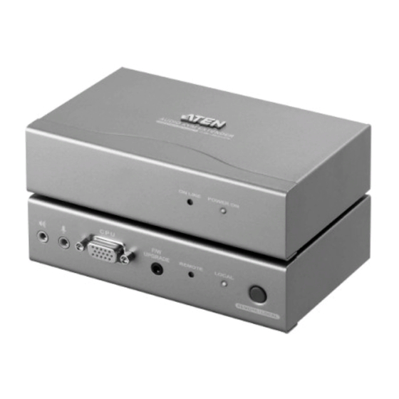
Page 16: Ce-300R (Remote Unit) Front View
CE-300 User Manual CE-300R (Remote Unit) Front View Component Description On Line / Power On These LEDs indicate the operating status of the Local and LEDs Remote units (see page 12, for details). -
Page 17: Ce-300L / Ce-300R Rear View
The monitor connector of the custom KVM cable supplied with this package plugs into this port. Note: If you are combining the CE-300 with a KVM switch, the custom KVM cable connects back to the respective ports on the Console section of the... - Page 18 CE-300 User Manual This Page Intentionally Left Blank...
-
Page 19: Hardware Setup
Chapter 2 Hardware Setup 1. Important safety information regarding the placement of this device is provided on page iv. Please review it before proceed- ing. 2. Make sure that power to all the devices you will be connecting up have been turned off. You must unplug the power cords of any computers that have the Keyboard Power On function. - Page 20 <Manual> User Manual CE-300L CE-300L CE-300L...
-
Page 21: Operation
Chapter 3 Operation The CE-300 Local and Remote Units each have two LEDs to indicate their operating status, as shown in the tables below: CE-300L (Local Unit) Operating Mode Local Auto Remote Local Lights to The LED is Of Lights when the local console is indicate that the active (the Remote LED is off). -
Page 22: Ce-300R (Remote Unit)
CE-300 User Manual CE-300R (Remote Unit) Indication Power Lights steadily to indicate that the connection to the Local Unit is Flashes when there is a problem with the connection to the Local Unit. On Line Lights when the remote console is active. -
Page 23: The Firmware Upgrade Utility
1. From a computer that is not part of your KVM installation go to our Inter- net support site and choose the model name that relates to your device (CE-300) to get a list of available Firmware Upgrade Packages. 2. Choose the Firmware Upgrade Package you want to install (usually the most recent), and download it to your computer. - Page 24 CE-300 User Manual 8. Use the provided Firmware Upgrade Cable to connect a COM port on your computer to the Firmware Upgrade Port on the switch.
-
Page 25: Starting The Upgrade
4. The Firmware Upgrade Utility Starting the Upgrade To upgrade your firmware: 1. Run the downloaded Firmware Upgrade Package file - either by double clicking the file icon, or by opening a command line and entering the full path to it. The Firmware Upgrade Utility Welcome screen appears: Note: The screens shown in this section are for reference only. - Page 26 CE-300 User Manual 3. Click Next to continue. The Firmware Upgrade Utility main screen appears: The Utility inspects your installation. All the devices capable of being upgraded by the package are listed in the Device List panel. 4. As you select a device in the list, its description appears in the Device Description panel.
-
Page 27: Upgrade Succeeded
4. The Firmware Upgrade Utility Upgrade Succeeded After the upgrade has completed, a screen appears to inform you that the procedure was successful: Click Finish to close the Firmware Upgrade Utility. After successfully upgrading the firmware, the switches automatically exit Firmware Upgrade Mode. - Page 28 CE-300 User Manual This Page Intentionally Left Blank...
-
Page 29: Appendix
Appendix Specifications Function CE-300L CE-300R Computer Connections 1 x 6-pin Mini-DIN Female (Purple) Connectors Console 1 x HDB-15 Female (Blue) Video 1 x 6-pin Mini-DIN Female (Green) Mouse Speaker 1 x Mini Stereo Jack (Green) Microphone 1 x Mini Stereo Jack (Pink) KVM Port Keyboard 1 x SPHD-15 Female (Yellow) -
Page 30: Tp Wiring Diagram
CE-300 User Manual TP Wiring Diagram PAIR 3 PAIR 2 PAIR 1 PAIR 4 1 2 3 4 5 6 W-O O W-G Bl W-Bl G W-Br Br JACK POSITIONS T568B AT&T 258A TP Pin Assignments Assignment /V OUT B... -
Page 31: Troubleshooting
Appendix Troubleshooting Problem Action No Video Make sure that all cables are securely plugged into their sockets. Limited Warranty IN NO EVENT SHALL THE DIRECT VENDOR'S LIABILITY EXCEED THE PRICE PAID FOR THE PRODUCT FROM DIRECT, INDIRECT, SPECIAL, INCIDENTAL, OR CONSEQUENTIAL DAMAGES RESULTING FROM THE USE OF THE PRODUCT, DISK, OR ITS DOCUMENTATION. - Page 32 CE-300 User Manual...
- Page 33 <Manual> User Manual Contents FCC Information ..........ii User Notice .
- Page 34 <Manual> User Manual...
Need help?
Do you have a question about the CE-300 and is the answer not in the manual?
Questions and answers