Table of Contents
Advertisement
Quick Links
Advertisement
Table of Contents

Subscribe to Our Youtube Channel
Related Manuals for ATEN CE350


Summary of Contents for ATEN CE350
- Page 1 PS/2 KVM Extender CE350 / CE370 User Manual www.aten.com...
-
Page 2: Fcc Information
CE350 / CE370 User Manual FCC Information This is an FCC Class A product. In a domestic environment this product may cause radio interference in which case the user may be required to take adequate measures. This equipment has been tested and found to comply with the limits for a Class A digital device, pursuant to Part 15 of the FCC Rules. -
Page 3: User Information
CE350 / CE370 User Manual User Information Online Registration Be sure to register your product at our online support center: International http://support.aten.com North America http://www.aten-usa.com/product_registration Telephone Support For telephone support, call this number: International 886-2-8692-6959 China 86-10-5255-0110 Japan 81-3-5615-5811 Korea... -
Page 4: Package Contents
* Features may have been added to the CE350 / CE370 since this manual was printed. Please visit our website to download the most up-to-date version of the manual. -
Page 5: Table Of Contents
CE350 / CE370 User Manual Contents FCC Information ..........ii RoHS. - Page 6 CE350 ........
-
Page 7: About This Manual
An overview of the information found in the manual is provided below. Chapter 1, Introduction, introduces you to the CE350 / CE370 system. Its purpose, features and benefits are presented, and its front and back panel components are described. -
Page 8: Conventions
For information about all ATEN products and how they can help you connect without limits, visit ATEN on the Web or contact an ATEN Authorized Reseller. Visit ATEN on the Web for a list of locations and telephone numbers: International http://www.aten.com... -
Page 9: Introduction
Because it allows access to a computer system from a remote console, the CE350 / CE370 is perfect for use in any type of installation where you need to place the console where it is conveniently accessible, but you want the system equipment to reside in a safe location –... - Page 10 CE350 / CE370 User Manual (Continued from previous page.) Further CE350 / CE370 key features are built-in 8KV/15KV ESD protection and 2KV surge protection, and color adjust picture compensation pushbuttons on the Remote Unit to adjust the picture on the remote console. Remote video is adjusted automatically and the settings are saved.
-
Page 11: Features
1. Introduction Features Local and Remote Units connect at distances up to 300 m using Cat 5e cable Deskew Function (CE370 only) – automatically synchronizes the time delay of RGB signals to compensate for distance On Screen Display (CE370 only) – conveniently adjust video quality with the intuitive OSD menu system Adjustable gain control –... -
Page 12: Requirements
KVM Cable that is provided with this package. Cat 5e cable is required to connect the Local and Remote CE350 / CE370 Units. Cable of a lower standard will result in degrading of the video signal. -
Page 13: Operating Systems
1. Introduction Operating Systems Supported operating systems are shown in the table, below: Version Windows 2000, 2003, 2008, XP, Vista, 7 Linux RedHat 9.0 and higher SuSE 10 / 11.1 and higher Debian 3.1 / 4.0 Ubuntu 7.04 / 7.10 UNIX FreeBSD 5.5 / 6.1 / 6.2... -
Page 14: Components
CE350L / CE370L (Local Units) Front View Component Description KVM Port Section If you are combining the CE350 / CE370 with a KVM switch, the PS/2 KVM cable that links to the respective ports on the Console section of the switch plugs into these ports. -
Page 15: Ce350R (Remote Unit) Front View
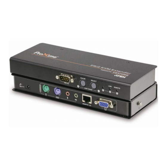
1. Introduction CE350R (Remote Unit) Front View Component Description RS-232 Serial Port RS-232 serial devices – such as touchscreens or barcode scanners – plug into this port. Picture Compensation These pushbuttons adjust the video quality of the Pushbuttons remote console. See CE350R Compensation Control, page 21 for details. -
Page 16: Ce370Rq (Remote Unit) Front View
CE350 / CE370 User Manual CE370RQ (Remote Unit) Front View Component Description RS-232 Serial Port RS-232 serial devices – such as touchscreens or barcode scanners – plug into this port. Deskew and Picture These pushbuttons adjust the video quality of the Compensation remote console. -
Page 17: Rear View
1. Introduction Rear View Side View Component Description Power Jack The cable from the DC Power adapter connects here. Audio Ports These mini stereo ports are for the speakers (green) and microphone (pink). Remote I/O The Cat 5e cable that connects the Remote and Local Units plugs in here. - Page 18 CE350 / CE370 User Manual This Page Intentionally Left Blank...
-
Page 19: Hardware Setup
Keyboard Power On function. Rack Mounting For convenience and flexibility, the CE350 / CE370 can be mounted on system racks. To rack mount a unit do the following: 1. Using the screws provided in the Rack Mount Kit, screw the mounting... - Page 20 CE350 / CE370 User Manual 2. Screw the bracket into any convenient location on the rack. Note: These screws are not provided. We recommend that you use M5 x 12 Phillips Type I cross, recessed type screws.
-
Page 21: Installation
Chapter 2. Hardware Setup Installation Grounding To prevent damage to your installation it is important that all devices are properly grounded. 1. Use two grounding wires to ground both units by connecting one end of the wire to the grounding terminal, and the other end of the wire to a suitable grounded object. - Page 22 CE350 / CE370 User Manual 3. For increased grounding protection, use STP (shielded twisted pair) cable to connect the Local and Remote Units. There are two methods that can be used: a) In addition to the eight paired wires, STP cable also contains a grounding wire.
-
Page 23: Setting Up
Chapter 2. Hardware Setup Setting Up Setting up the CE350 / CE370 PS/2 KVM Extender system is simply a matter of plugging in the cables. Make sure that all the equipment to be connected up is powered Off. Refer to the installation diagram on the following page and do the following: 1. -
Page 24: Installation Diagrams
CE350 / CE370 User Manual Installation Diagrams Rear View CE350L / CE370L Cat 5e cable CE350R /370RQ... -
Page 25: Front View
Chapter 2. Hardware Setup Front View Local PC PS/2 KVM cable Note: The serial port on the CE350L / CE370L connects to the computer; the serial port on the CE350R / CE370RQ (not shown) connects to a serial device (optional). - Page 26 CE350 / CE370 User Manual This Page Intentionally Left Blank...
-
Page 27: Operation
Chapter 3 Operation Operating Modes The CE350 / CE370 PS/2 KVM Extender has three operating modes: Local, Auto, and Remote, as described in the table below: Mode Description Local Only the local console has KVM access. The remote console’s keyboard and mouse input is disabled. -
Page 28: Mode Selection
Mode Selection The Operating Mode Pushbutton, located on the Local Unit’s front panel, controls the operating mode of the CE350 / CE370 PS/2 KVM Extender system. Pressing the switch toggles through Local and Auto operating modes. Note: Remote mode cannot be selected. The remote console can get control only when the Operating Mode Pushbutton on the CE350L / CE370L is toggled to Auto and the local console is idle. -
Page 29: Picture Compensation
3. Operation Picture Compensation The CE350 / CE370 features ASC (Auto Signal Compensation), which automatically adjusts the video and stores the settings. However, the quality of the video display can deteriorate with distance, so the video can also be adjusted manually. The pushbuttons on the front panel of the Remote Units (indicated in the illustration, below) adjust the quality of the video on the remote console. -
Page 30: Ce370Rq Deskew
CE350 / CE370 User Manual CE370RQ Deskew Button Description Color / + 1. Press and release to enter Red color mode. Use (+) and (–) to adjust. 2. Press and hold for two seconds to invoke the OSD (when no color is selected). -
Page 31: Led Display
3. Operation LED Display The CE350 / CE370 Local and Remote Units have front panel LEDs to indicate their operating status, as shown in the tables, following: CE350L / CE370L(Local Units) Operating Mode Local Auto Local Lights to indicate that the local... -
Page 32: Ce350R (Remote Unit)
Picture Compensation Lights when a Picture Compensation pushbutton has been (Blue) pushed (+ or –) and the CE350 is adjusting the video gain.* Lights steadily to indicate that the video gain adjustment has been completed and saved. Note: There is a 10-second timeout once a Picture Compensation pushbutton... -
Page 33: Ce370Rq (Remote Unit)
3. Operation CE370RQ (Remote Unit) Indication Flashes to indicate that the BLUE color is selected and the (Blue) pushbutton can be used to adjust the delay time of the BLUE color. Link / G Lights Orange to indicate that the connection to the Local unit (Orange/Green) is ok. - Page 34 CE350 / CE370 User Manual This Page Intentionally Left Blank...
-
Page 35: Appendix
Appendix Safety Instructions General Read all of these instructions. Save them for future reference. Follow all warnings and instructions marked on the device. Do not place the device on any unstable surface (cart, stand, table, etc.). If the device falls, serious damage will result. Do not use the device near water. - Page 36 CE350 / CE370 User Manual If an extension cord is used with this device make sure that the total of the ampere ratings of all products used on this cord does not exceed the extension cord ampere rating. Make sure that the total of all products plugged into the wall outlet does not exceed 15 amperes.
-
Page 37: Rack Mounting
Appendix Rack Mounting Before working on the rack, make sure that the stabilizers are secured to the rack, extended to the floor, and that the full weight of the rack rests on the floor. Install front and side stabilizers on a single rack or front stabilizers for joined multiple racks before working on the rack. -
Page 38: Technical Support
CE350 / CE370 User Manual Technical Support Technical support is available both by email and online (with a browser over the web): International For online technical support – including troubleshooting, documentation, and software updates: http://support.aten.com For telephone support, see Telephone Support, page iii:... -
Page 39: Specifications
Appendix Specifications CE350 Function CE350L CE350R Connectors Console Keyboard 1 x 6-pin Mini-DIN Female (Purple) Ports Video 1 x HDB-15 Female (Blue) Mouse 1 x 6-pin Mini-DIN Female (Green) Speakers 1 x Mini Stereo Jack Female (Green) Mic. 1 x Mini Stereo Jack Female (Pink) -
Page 40: Ce370
CE350 / CE370 User Manual CE370 Function CE370L CE370RQ Connectors Console Keyboard 1 x 6-pin Mini-DIN Female (Purple) Ports Video 1 x HDB-15 Female (Blue) Mouse 1 x 6-pin Mini-DIN Female (Green) Speakers 1 x Mini Stereo Jack Female (Green) Mic. -
Page 41: Troubleshooting
Appendix Troubleshooting Operation problems can be due to a variety of causes. The first step in solving them is to make sure that all cables are securely attached and seated completely in their sockets. Problem Action No video Make sure that all cables are securely plugged into their sockets. -
Page 42: About Sphd Connectors
CE350 / CE370 User Manual About SPHD Connectors This product uses SPHD connectors for its KVM and/or Console ports. We have specifically modified the shape of these connectors so that only KVM cables that we have designed to work with this product can be connected.
Need help?
Do you have a question about the CE350 and is the answer not in the manual?
Questions and answers