Table of Contents
Advertisement
Quick Links
Advertisement
Table of Contents

Subscribe to Our Youtube Channel
Related Manuals for ATEN CE800b


Summary of Contents for ATEN CE800b
- Page 1 USB KVM Extender CE800 User Manual www.aten.com...
-
Page 2: Fcc Information
CE800 User Manual FCC Information This is an FCC Class A product. In a domestic environment this product may cause radio interference in which case the user may be required to take adequate measures. This equipment has been tested and found to comply with the limits for a Class A digital device, pursuant to Part 15 of the FCC Rules. -
Page 3: User Information
PLEASE VERIFY THAT THE VOLTAGE SETTING IS CORRECT BEFORE USE. This ATEN product is specifically designed and manufactured for the operation and management of computer mainframe and communications equipment used in network management centers. -
Page 4: Package Contents
© Copyright 2008–2012 ATEN® International Co., Ltd. Manual Part No. PAPE-0300-AT2G Manual Date: 2012-02-23 ATEN and the ATEN logo are registered trademarks of ATEN International Co., Ltd. All rights reserved. All other brand names and trademarks are the registered property of their respective owners. -
Page 5: Table Of Contents
Setting Up ..........13 Standard Installation – CE800B to PC ......15 Advanced Installation –... - Page 6 CE800 User Manual Overview ..........20 Administrator Main Screen .
-
Page 7: About This Manual
CE800 User Manual About this Manual This User Manual is provided to help you get the most from your CE800 system. It covers all aspects of installation, configuration and operation. An overview of the information found in the manual is provided below. Chapter 1, Introduction, introduces you to the CE800 USB KVM Extender system. -
Page 8: Conventions
For information about all ATEN products and how they can help you connect without limits, visit ATEN on the Web or contact an ATEN Authorized Reseller. Visit ATEN on the Web for a list of locations and telephone numbers: International http://www.aten.com... -
Page 9: Introduction
Chapter 1 Introduction Overview The CE800 USB KVM Extender with on-board audio allows access to a computer system from a remote console (USB keyboard and mouse, monitor, stereo speakers, and microphone). It is perfect for factory and construction sites, or any type of installation where the console needs to be in a conveniently accessible location, but you want the system equipment to reside in a safe place –... -
Page 10: Features
CE800 User Manual Features Cat 5e (or higher) cable connects the Local and Remote Units – up to 250 m (825 ft) apart Dual console operation – control your system(s) from both the local and remote consoles Pushbutton selection of the active console Built-in USB port on both units supports external USB Mass Storage compliant flash drives for easy file sharing Special security feature requires login when connecting an external USB... -
Page 11: System Requirements
1. Introduction System Requirements Consoles Two VGA, SVGA, or multisync monitors capable of the highest resolution that you will be using on any computer in the installation Two USB keyboards Two USB mice Stereo microphone and stereo speakers (Optional) Note: If you connect a DDC type monitor to the Local Unit, the monitor that connects to the Remote Unit must be able to support the highest video resolution that the DDC monitor can provide. -
Page 12: Operating Systems
CE800 User Manual Operating Systems Supported operating systems are shown in the table, below: Version Windows 2000 and higher Linux RedHat 7.1 and higher Mandrake 9.0 and higher SUSE 10 and higher UNIX FreeBSD 4.2 and higher AIX 4.3 and higher Novell Netware 6.0 and higher... -
Page 13: Ce800Bl (Local Unit) Front View
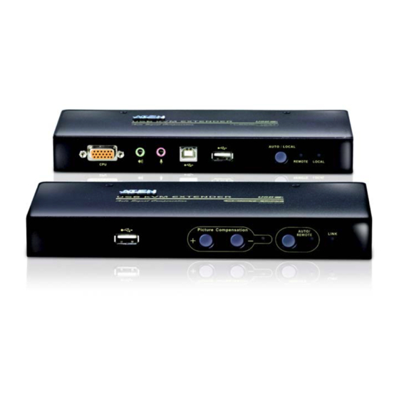
1. Introduction CE800 (Local Unit) Front View AUTO / LOCAL Component Description KVM Port Section This section is made up of a microphone jack, speaker jack, and KVM (keyboard, video, mouse) data connectors. The custom cable set that links the CE800 to your local KVM console plugs in here. -
Page 14: Ce800Br (Remote Unit) Front View
CE800 User Manual CE800 (Remote Unit) Front View AUTO / REMOTE Component Description USB Peripheral Port External USB Mass Storage compliant flash drives plug into this port. Picture These switches adjust the picture quality of the remote Compensation console. See Picture Compensation, page 18 for details. Switches Picture Flashes to indicate that picture quality has been... -
Page 15: Ce800Bl / Ce800Br Rear View
1. Introduction CE800 / CE800 Rear View Side View Component Description Power Jack The cable from the DC Power Adapter plugs into this jack. Keyboard and The console USB keyboards and mice plug into these ports. Mouse Ports The ports are color coded and marked with an icon to identify themselves. - Page 16 CE800 User Manual This Page Intentionally Left Blank...
-
Page 17: Hardware Setup
Chapter 2 Hardware Setup Before You Begin 1. Important safety information regarding the placement of this device is provided on page 37. Please review it before proceeding. 2. Make sure that power to all the devices you will be connecting up have been turned off. - Page 18 CE800 User Manual 2. Screw the bracket into any convenient location on the rack. Note: The rack screws are not provided. We recommend that you use M5 x 12 Phillips Type I cross, recessed type screws.
-
Page 19: Installation
2. Hardware Setup Installation Grounding To prevent damage to your installation it is important that all devices are properly grounded. 1. Use two grounding wires to ground both units by connecting one end of the wire to the grounding terminal, and the other end of the wire to a suitable grounded object. - Page 20 CE800 User Manual 4. For increased grounding protection, use STP (shielded twisted pair) cable to connect the local and remote units. There are two methods that can be used: a) In addition to the eight paired wires, STP cable also contains a grounding wire.
-
Page 21: Setting Up
2. Hardware Setup Setting Up Setting up the USB KVM Extender System is simply a matter of plugging in the cables. Refer to the diagrams on the following pages as you perform the following steps (the diagram numbers correspond to the numbers of the steps): 1. - Page 22 CE800 User Manual 5. Connect one end of a Cat 5e twisted pair cable to the Link port on the CE800 ; connect the other end of the Cat 5e twisted pair cable into the Link port on the CE800 Note: Cat 5e cable is not supplied with this package.
-
Page 23: Standard Installation - Ce800B To Pc
2. Hardware Setup Standard Installation – CE800 to PC CE800 (rear) CE800 (front) Cat 5e Cable up to 250 m USB Cable Custom KVM cable CE800 (rear) CE800 (front) -
Page 24: Advanced Installation - Ce800B To Kvm Switch
CE800 User Manual Advanced Installation – CE800 to KVM Switch CE800 (front) USB Cable Custom KVM cable USB KVM Switch (rear) -
Page 25: Operation
Chapter 3 Operation Basic Operation Operating Modes The CE800 USB KVM Extender utilizes three operating modes: Auto, Local, and Remote, as described in the table below: Mode Description Local Only the local console has complete access. Although operators at both consoles can see the display, only the local console operator has keyboard and mouse access and control. -
Page 26: Picture Compensation
CE800 User Manual Likewise, if the system is in Remote Mode, the Local unit’s selection switch is inactive – the Local operator cannot take over control. The Local selection switch only becomes active after the Remote selection switch is pressed to put the system back into Auto Mode. -
Page 27: Usb Mass Storage
3. Operation CE800 (Remote Unit) Status Indication Remote Remote Mode is in effect. The Remote console has keyboard and mouse input control. Local Mode is in effect. The Local console has keyboard and mouse input control. Flashing Auto Mode is in effect. Neither console has keyboard and mouse input control. -
Page 28: Osd Operation
CE800 User Manual OSD Operation Overview The CE800 USB KVM Extender provides a convenient menu driven On Screen Display (OSD) to handle its configuration parameters. All procedures start from the OSD Main Screen. To pop up the Main Screen: 1. Tap the OSD Hotkey (Scroll Lock) twice. Note: [Scroll Lock] is the default OSD hotkey. -
Page 29: Administrator Main Screen
3. Operation Administrator Main Screen After you log in to the OSD, if you are the administrator, a screen similar to the one below appears: ESC : EXIT : UP ENTER : SELECT : DOWN ADMINISTRATOR SET USERNAME AND PASSWORD OSD HOTKEY HOTKEY COMMAND MODE (ON) HOTKEY... -
Page 30: Administrator Configuration
CE800 User Manual Administrator Configuration The configuration settings that the administrator is allowed to make are explained in the following table: Setting Function SET USERNAME AND This function is used to set Usernames and Passwords PASSWORD for the Administrator and Users: 1. - Page 31 3. Operation Setting Function RESTORE DEFAULT Selecting Y (Yes) undoes all changes and returns the VALUES CE800 ’s setup to the original factory default settings. SET OPERATING SYSTEM This function specifies the operating platform of the computer attached to the CE800 .
-
Page 32: User Configuration
CE800 User Manual User Configuration The CE800 USB KVM Extender supports up to four user accounts in addition to the administrator. When users invoke the OSD, they get an OSD Main screen allows them to modify some of the configuration settings made by the administrator. -
Page 33: Hotkey Setting Mode
3. Operation Hotkey Setting Mode In addition to the OSD, the administrator and users can also use hotkey combinations to configure a number of the CE800 USB KVM Extender’s working environment parameters. All Hotkey operations begin by invoking Hotkey Setting Mode (HSM). Invoking HSM To invoke HSM, do the following: 1. -
Page 34: Alternate Hsm Invocation Keys
CE800 User Manual Alternate HSM Invocation Keys An alternate set of HSM invocation keys is provided in case the default set conflicts with programs running on the computers. To switch to the alternate HSM invocation set, do the following: 1. Invoke HSM (see page 25). 2. -
Page 35: Enable / Disable Hotkeys
3. Operation Enable / Disable Hotkeys In case a conflict occurs with programs running on the computer, you may wish to disable the hotkey function. To disable the hotkey function do the following: 1. Invoke HSM (see page 25). 2. Press and release [X] [Enter]. Note: This procedure is a toggle between enabling / disabling the hotkey function. -
Page 36: Usb Reset
CE800 User Manual USB Reset Sometimes the USB keyboard and mouse connection to the CE800 needs to be reset. Instead of unplugging and replugging them, a hotkey combination can perform the reset, as follows: 1. Invoke HSM (see page 25). 2. -
Page 37: Keyboard Emulation
Chapter 4 Keyboard Emulation Mac Keyboard The PC compatible (101/104 key) keyboard can emulate the functions of the Mac keyboard. The emulation mappings are listed in the table below. PC Keyboard Mac Keyboard [Shift] Shift [Ctrl] Ctrl [Ctrl] [1] [Ctrl] [2] [Ctrl] [3] [Ctrl] [4] [Alt]... -
Page 38: Sun Keyboard
CE800 User Manual Sun Keyboard The PC compatible (101/104 key) keyboard can emulate the functions of the Sun keyboard when the Control key [Ctrl] is used in conjunction with other keys. The corresponding functions are shown in the table below. PC Keyboard Sun Keyboard [Ctrl] [T]... -
Page 39: The Firmware Upgrade Utility
New firmware upgrade packages are posted on our web site as new firmware revisions become available. Check the web site regularly to find the latest packages and information relating to them: http://www.aten.com Before You Begin To prepare for the firmware upgrade, do the following: 1. - Page 40 CE800 User Manual 5. Make sure both units are connected by the Cat 5e cable, then plug in the Remote unit’s power adapter. 6. Press and hold the Local unit’s Selection button, then plug in the Local unit’s power adapter. 7.
-
Page 41: Starting The Upgrade
5. The Firmware Upgrade Utility Starting the Upgrade To upgrade your firmware: 1. Run the downloaded Firmware Upgrade Package file – either by double clicking the file icon, or by opening a command line and entering the full path to it. The Firmware Upgrade Utility Welcome screen appears: Note: The screens shown in this section are for reference only. - Page 42 CE800 User Manual 3. Click Next to continue. The Firmware Upgrade Utility main screen appears: The Utility inspects your installation. All the devices capable of being upgraded by the package are listed in the Device List panel. 4. As you select a device in the list, its description appears in the Device Description panel.
-
Page 43: Upgrade Succeeded
5. The Firmware Upgrade Utility Upgrade Succeeded After the upgrade has completed, a screen appears to inform you that the procedure was successful: Click Finish to close the Firmware Upgrade Utility. After successfully upgrading the firmware, the switches automatically exit Firmware Upgrade Mode. - Page 44 CE800 User Manual This Page Intentionally Left Blank...
-
Page 45: Appendix
Appendix Safety Instructions General Read all of these instructions. Save them for future reference. Follow all warnings and instructions marked on the device. To prevent damage to your installation it is important that all devices are properly grounded. Do not place the device on any unstable surface (cart, stand, table, etc.). If the device falls, serious damage will result. - Page 46 CE800 User Manual Position system cables and power cables carefully; Be sure that nothing rests on any cables. When connecting or disconnecting power to hot-pluggable power supplies, observe the following guidelines: Install the power supply before connecting the power cable to the power supply.
-
Page 47: Rack Mounting
Rack Mounting Before working on the rack, make sure that the stabilizers are secured to the rack, extended to the floor, and that the full weight of the rack rests on the floor. Install front and side stabilizers on a single rack or front stabilizers for joined multiple racks before working on the rack. -
Page 48: Technical Support
CE800 User Manual Technical Support International For online technical support – including troubleshooting, documentation, and software updates: http://support.aten.com For telephone support, see Telephone Support, page iii North America Email Support support@aten-usa.com Online Troubleshooting http://www.aten-usa.com/support Technical Documentation Support Software Updates Telephone Support... -
Page 49: Specifications
Specifications Function CE800 CE800 Computer Connections 1 x USB Type A Female (White) Connectors Console Keyboard 1 x HDB-15 Female (Blue) Video 1 x USB Type A Female (White) Mouse Speaker 1 x Mini Stereo Jack (Green) Microphone 1 x Mini Stereo Jack (Pink) Keyboard / 1 x SPHD-15 Female Ports... -
Page 50: Troubleshooting
CE800 User Manual Troubleshooting Operation problems can be due to a variety of causes. The first step in solving them is to make sure that all cables are securely attached and seated completely in their ports. In addition, updating the product’s firmware may solve problems that have been discovered and resolved since the prior version was released. -
Page 51: Clear Login Information
Clear Login Information If you are unable to perform an Administrator login (because the Username and Password information has become corrupted or you have forgotten it, for example) you can clear the login information with the following procedure: 1. Power off the CE800 and remove its housing. -
Page 52: About Sphd Connectors
CE800 User Manual About SPHD Connectors This product uses SPHD connectors for its KVM and/or Console ports. We have specifically modified the shape of these connectors so that only KVM cables that we have designed to work with this product can be connected. Limited Warranty IN NO EVENT SHALL THE DIRECT VENDOR'S LIABILITY EXCEED THE PRICE PAID FOR THE PRODUCT FROM DIRECT, INDIRECT, SPECIAL, INCIDENTAL, OR... - Page 53 Administrator Configuration 22 Keyboard Emulation Alternate OSD keys 26 Mac 29 Sun 30 Keyboard Language 23 Basic Operation 17 Keyboard Operating Platform 27 Change Password 24 Mode Selection 17 Clear login information 43 Configuration Administrator 22 Online User 24 Registration iii Operating Modes 17 Operating System 23 default password 43...
- Page 54 CE800 User Manual Rack mounting 39 Password 22 Reset 28 SJ/T 11364-2006 ii USB Mass Storage 19 User Authentication 22 User Configuration 24 Technical Support 40 User Notice iii Telephone support iii Username 22...
Need help?
Do you have a question about the CE800b and is the answer not in the manual?
Questions and answers