Table of Contents
Advertisement
Instructions - Parts
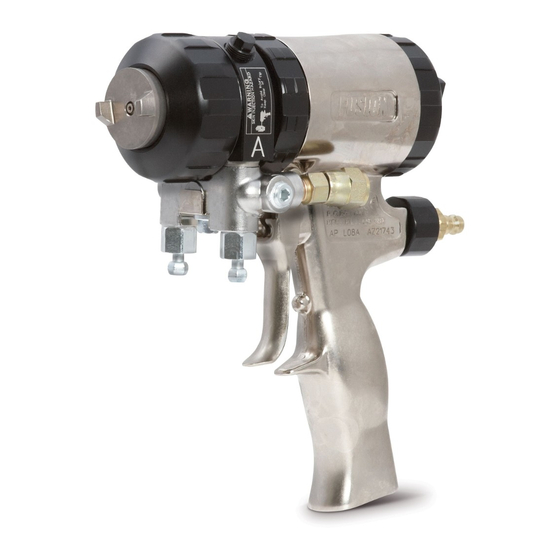
Plural Component, Impingement Mix
Air Purge Spray Gun
For use with non-flammable foam and polyurea.
Not for use in explosive atmospheres.
3500 psi (24.5 MPa, 245 bar) Maximum Fluid Working Pressure
80-130 psi (0.56-0.9 MPa, 5.6-9.0 bar) Air Inlet Pressure Range
200°F (94°C) Maximum Fluid Temperature
Important Safety Instructions
Read all warnings and instructions in this manual.
Save these instructions.
US Patent Number D479,305
Korean Patent 338185
Australian Patent Number 152610
Graco Inc. P.O. Box 1441 Minneapolis, MN 55440-1441
Copyright 2002, Graco Inc. is registered to I.S. EN ISO 9001
309550U
TI2408-1A
Advertisement
Table of Contents

Subscribe to Our Youtube Channel
Related Manuals for Graco FUSION 309550U


Summary of Contents for Graco FUSION 309550U
- Page 1 Read all warnings and instructions in this manual. Save these instructions. US Patent Number D479,305 Korean Patent 338185 Australian Patent Number 152610 Graco Inc. P.O. Box 1441 Minneapolis, MN 55440-1441 Copyright 2002, Graco Inc. is registered to I.S. EN ISO 9001 309550U TI2408-1A...
-
Page 2: Table Of Contents
Graco Standard Warranty ....46 Graco Information ......46... -
Page 3: List Of Models/Mix Chamber Selection Guide
List of Models/Mix Chamber Selection Guide Round Pattern Guns Impingement Gun Part No., Series Part No. 246099, A AR2020 246100, A AR2929 248617, A AR3737 246101, A AR4242 246102, A AR5252 246103, A AR6060 246104, A AR7070 246105, A AR8686 255201, A AR4242 255202, A... -
Page 4: Flat Pattern Guns
List of Models/Mix Chamber Selection Guide Flat Pattern Guns Mix Chamber Impingement Gun Part No., Series Part No. 247101, A AF2020 .020 (0.50) 247102, A AF2020 .020 (0.50) 247103, A AF2020 .020 (0.50) 247104, A AF2020 .020 (0.50) 247107, A AF2020 .020 (0.50) 247108, A... -
Page 5: Flat Pattern Stud Wall Gun
Flat Pattern Guns, continued (11.4) 2.25 (8.55) (5.7) 0.75 (2.85) 1000 (3.5, 35) (6.9, 69) Flat Pattern Stud Wall Gun See manual number 311071 for more information. Mix Chamber Impingement Gun Part Port Size No., Series Part No. in. (mm) 249525 AF4242 .042 (1.00) -
Page 6: Spatter Pattern Gun
List of Models/Mix Chamber Selection Guide Spatter Pattern Gun Mix Chamber Impingement Gun Part No., Series Part No. 248408 A AR7070 Wide Round Pattern Gun Mix Chamber Impingement Gun Part No., Series Part No. 249529 AW3939 .039 (0.99) 249530 AW4646 .046 (1.17) Four-Hose Gun Wide Round Pattern Gun with Four-Hose Recirculating Gun Manifold... - Page 7 PERSONAL PROTECTIVE EQUIPMENT You must wear proper protective equipment when operating, servicing, or when in the operating area of the equipment to help protect you from serious injury, including eye injury, inhalation of toxic fumes, burns, and hearing loss. This equipment includes but is not limited to: •...
- Page 8 Misuse can cause serious injury or death. • For professional use only. • Use equipment only for its intended purpose. Call your Graco distributor for information. • Read manuals, warnings, tags, and labels before operating equipment. Follow instructions. • Check equipment daily. Repair or replace worn or damaged parts immediately.
-
Page 9: Overall View
Overall View Key: A Side Fluid Valve (ISO) B Side Fluid Valve (RESIN) Air Cap Air Line Quick Coupler Muffler Fluid Housing Grease Fitting (under cap) Handle Optional Air Inlet Cleanoff Air Valve 309550U Piston Safety Lock Gun Fluid Manifold Mix Chamber Nozzle Optional Fluid Inlets (A Side Shown) Lock Ring... -
Page 10: Isocyanate Hazard
Check your local electrical code and proportioner man- ual for detailed grounding instructions. Ground the spray gun through connection to a Graco-approved grounded fluid supply hose. Piston Safety Lock Engage piston safety lock whenever you stop spray- ing, to avoid accidental triggering. -
Page 11: Turning Air Cap
Turning Air Cap WARNING Read warnings, page 7. Follow Pressure Relief Procedure, page 15. Close fluid valves A and B before turning air cap (C). 309550U Loss of Air Pressure In event of loss of air pressure, gun will continue to spray. -
Page 12: Setup
Setup Setup Close fluid valves A and B. Connect A (ISO) and B (RESIN) fluid hoses to fluid manifold. B (RESIN) Engage piston safety lock, page 10. Connect gun air whip hose (V) and air valve (W*) to main air hose. Attach fluid manifold (M) to gun. To change position of fluid manifold or use optional fluid inlets, see pages 16 and 17. - Page 13 Open cleanoff air valve (K) 1/4-1/2 turn and trigger gun to check that cleanoff air is flowing. Adjust as desired.This step does not apply with spatter spray gun 248408. Engage piston safety lock, page 10. Turn on proportioner. Open B (RESIN) fluid valve (about three half turns).
-
Page 14: Shutdown
Grease gun daily to prevent 2 component curing and keep fluid passages clean. Purge air carries grease mist through air chamber (AC), impinge- ment ports (IP), and out mix chamber nozzle (N), coating all surfaces. Use Graco 117773 Grease, see page 43. Purge Air Fluid... -
Page 15: Pressure Relief Procedure
Pressure Relief Procedure WARNING Read warnings, page 7. Relieve pressure before cleaning or repairing gun. Engage piston safety lock, page 10. CAUTION Air supply is required for gun actuation. Do not dis- connect gun air supply until fluid pressure is relieved. Close fluid valves A and B. -
Page 16: Optional Configurations
Optional Configurations Optional Configurations Optional Fluid Manifold Position Fluid manifold is mounted to bottom of gun, with A side on left, viewed from operator’s position at back of gun. If desired, manifold may be moved to top of gun. Doing this will reposition A side parts (fluid inlet swivel, check valve, side seal cartridge, and mix chamber) to right. -
Page 17: Optional Hose Position
Optional Hose Position Fluid inlet swivels and air quick disconnect fitting point to rear. If desired, these positions can be changed so hoses travel downward. CAUTION To prevent cross-contamination of gun’s wetted parts, do not interchange A component (isocyanate) and B component (resin) parts. -
Page 18: Flat Spray Tips
Flat Spray Tips Flat Spray Tips Follow Pressure Relief Procedure, page 15. Remove air cap (10) and flat spray tip (39). Inspect o-ring (40). If tip is stuck, pry off with small screwdriver or pull off with pliers. Tip is hardened to resist damage. To clean, soak tip in compatible solvent, see page 20. -
Page 19: Maintenance
Maintenance Supplied Tool Kit • Hex Nut Driver; 5/16 • Screwdriver; 1/8 blade • Nozzle Drill Bit; various sizes depending on nozzle size. See T 1, page 21. ABLE • Impingement Port Drill Bit; various sizes depending on port size. See T 3, page 22. -
Page 20: Flush Gun
Maintenance Flush Gun If it is necessary to flush gun, use following procedure. WARNING Read warnings, page 8. Follow Pressure Relief Procedure, page 15. Flush with compatible solvent into a grounded metal pail, holding a metal part of fluid manifold firmly to side of pail. -
Page 21: Clean Mix Chamber Nozzle
Clean Mix Chamber Nozzle Engage piston safety lock, page 10. Refer to T 1. Also see identification chart ABLE under Drill Bit Kits, page 39. Use the appropriate size drill bit to clean mix chamber nozzle (N). If necessary, clean air cap (C) gently with stiff brush. Table 1: Nozzle Drill Bit Sizes Round Spray Mix Chamber... - Page 22 Maintenance Push mix chamber forward until impingement ports (IP) are visible. See T 3 for appropriate size ABLE drill to clean ports. Also see identification chart under Drill Bit Kits, page 39. Some mix chambers have counterbored holes (CB) and require two drill sizes to clean impingement ports completely.
-
Page 23: Troubleshooting
Troubleshooting Follow Pressure Relief Procedure, page 15, before checking or repairing gun. PROBLEM Gun does not fully actuate when trig- gered. Fluid does not spray when gun is fully actuated. Gun actuates slowly. Gun delays, then actuates abruptly. Loss of round pattern. Loss of flat pattern. - Page 24 Troubleshooting PROBLEM A and/or B fluid in gun air section. Fluid mist from mix chamber or air cap. Excessive overspray. Rapid buildup of material on air cap. Reduced cleanoff air. Excessive cleanoff air when fluid valves are closed and gun is trig- gered.
-
Page 25: Theory Of Operation
Theory of Operation Gun Triggered (Fluid Spraying) Mix chamber (19) moves back, shutting off purge air flow. Impingement ports (IP) align with fluid ports of side seals (18c), allowing fluid to flow through mix chamber nozzle (N). See page 13 to adjust cleanoff air valve (K). Purge Air Fluid Cleanoff Air... -
Page 26: Cutaway View
Troubleshooting Cutaway View 17 15 D E F 18 (A Side) B Side not shown 309550U... -
Page 27: Repair
Repair Tools Required Tools needed for complete gun repair: • adjustable wrench • flat head screwdriver (included) • 1/8 in. (3 mm) diameter rod • 5/16 hex nut driver (included) Lubrication Liberally lubricate all o-rings, seals, and threads. Lubri- cate threads and outside of lock ring (11). See page 43 to order lubricant. -
Page 28: Attach Front End
Repair Attach Front End WARNING Read warnings, page 7. Proper attachment of front end is critical. Do not operate gun if front end is loose or lock ring is not snug against handle. Engage piston safety lock, page 10. Push on air cap (C) until it is flush with front of gun. This ensures that mix chamber is all the way back. -
Page 29: Mix Chamber And Side Seal Cartridges
Mix Chamber and Side Seal Cartridges See page 3 for available mix chamber sizes. Follow Pressure Relief Procedure, page 15. Remove fluid manifold (M). Leave air connected. Flush gun to remove residual A and B compo- nents, page 20. Follow Pressure Relief Proce- dure, page 15. - Page 30 Repair Pull mix chamber (19) out rear of fluid housing. Inspect for damage and clean ports, page 21. Inspect o-ring (23) in front of fluid housing. CAUTION To prevent cross-contamination of the gun’s wetted parts, mix chamber is marked with an A and a notch (N) on back edge.
-
Page 31: Check Valves
Check Valves Before disassembling, press on ball (26c) to test check valve for proper movement and spring action. Follow Pressure Relief Procedure, page 15. Remove fluid manifold (M). Leave air connected. Clean Fluid Manifold, page 20. Flush gun to remove residual A and B compo- nents, page 20. -
Page 32: Piston
Repair Piston Follow Pressure Relief Procedure, page 15. Disconnect air (D) and remove fluid manifold (M). Remove Front End, page 27. Unscrew cylinder cap (5) and inspect o-ring (14). Push piston shaft to remove piston (15). Inspect piston o-ring (16) and shaft o-ring (17). Liberally lubricate piston o-rings. -
Page 33: Piston Safety Lock
Piston Safety Lock Follow Pressure Relief Procedure, page 15. Disconnect air (D) and remove fluid manifold (M). Unscrew cylinder cap (5). Hold piston stop (28) with wrench and unscrew from safety lock (4). Inspect spring (30) and o-rings (14, 24). Liberally lubricate o-rings and reassemble. -
Page 34: Parts
Parts Parts Round Pattern Gun Shown; see page 36 for additional parts and detail views ‡ ‡ ‡ ‡ ‡ 18; see ‡ detail above ‡ ‡ ‡ ‡ ‡ see detail at right Torque to 125-135 in-lb (14-15 N•m). Torque to 20-30 in-lb (2.3-3.4 N•m). - Page 35 Ref. Part No. Description 15B201 HANDLE 15B208 PLUG, air valve 248137 O-RING; PTFE; package of 6 ‡ ★ 15B206 LOCK, safety ★ 15B204 CAP, cylinder 192272 PIN 15B215 RING, lock ‡ 15B223 VALVE, cleanoff air ‡ 15B211 RING, retaining ‡ 15B210 AIR CAP;...
- Page 36 118575 SCREWDRIVER; 1/8 blade 55▲ 172479 TAG, warning; not shown 56▲ 15D235 SIGN, instruction; not shown 117773 GREASE CARTRIDGE; 3 oz; not shown; MSDS sheet available at www.graco.com Detail Views Flat Pattern Stud Wall Foam Detail Flat Pattern Detail †...
-
Page 37: Mix Chamber Kits
Mix Chamber Kits Round Pattern Guns Mix Chamber Kit Nozzle Nozzle Drill (includes drill bits) Orifice Bit Size, Size in. (mm) AR2020 0.042 #58 (1.00) AR2929 0.052 #55 (1.30) AR3737 0.052 #55 (1.30) AR4242 0.060 #53 (1.50) AR5252 0.070 #50 (1.75) AR6060 0.086 #44 (2.15) -
Page 38: Flat Tip Kits
Parts Flat Tip Kits Ref. No. 39, Pattern Size, in. (mm) Flat Spray Tip FT0424 low flow, 8-10 (203-254) FT0438 medium flow, 8-10 (203-254) FT0624 low flow, 12-14 (305-356) FT0638 medium flow, 12-14 (305-356) FT0838 medium flow, 16-18 (406-457) FT0848 high flow, 16-18 (406-457) Gun Repair Kits Read the chart left to right and top to bottom to find the quantity of each part in the kits. -
Page 39: Drill Bit Kits
Drill Bit Kits For cleaning gun ports and orifices. Illustrations are actual size, for comparison. Not all sizes are used with your gun. Kit Part No. Qty in Kit nominal 249115 246623 246810 7/64 246813 246624 3/32 246812 246625 248639 2.15 mm 249114 246811... -
Page 40: Air Purge Handle Cleanout Drill Kit
Parts Kit Part No. Qty in Kit nominal 246629 246808 248640 248618 248891 246807 246630 248892 246815 276984 246631 246816 246817 Air Purge Handle Cleanout Drill Kit 248969 Kit includes all 5 drill bits of extra long length needed to clean out the air passages in the Air Purge gun handle and fluid housing. -
Page 41: Accessories
Accessories Wide Pattern Mix Chamber Kits Kits include mix chamber and cleanout drills. To spray larger diameter patterns than the standard mix chambers. Pattern Diameter at 24 in. (609.6 mm) to target Kit Part No. in (mm) AW2222 8 (203.2) AW2828 15 (381.0) AW3333... -
Page 42: Hose Adapter Kits
Optional tip FTM762 available for lower flow and smaller pattern application. Hose Adapter Kits 246944 To connect non-Graco gun to Graco heated hose. 248029 To connect Graco Fusion gun to non-Graco D-gun hose set. 246945 To connect Graco Fusion gun to non-Graco heated hose. 10 (254) -
Page 43: Solvent Flush Canister Kit
Keeps gun clean while spraying. Pack of 10. Lubricant for Gun Rebuild 248279, 4 oz (113 gram) [10] High adhesion, water resistant, lithium-based lubricant. MSDS sheet available at www.graco.com. Grease Cartridge for Gun Shutdown 248280 Cartridge, 3 oz [10] Specially formulated low viscosity grease flows easily through gun passages, to prevent 2 component curing and keep fluid passages clean. -
Page 44: Circulation Manifold
Accessories Tip Cleanout Tool 15D234 Designed to fit CeramTip internal dome and flat tip slits. End for Air Purge Tips Circulation Manifold 246362 Attach to gun fluid manifold to enable preheating of hose. See manual 309818. End for Mechanical Purge Tips TI4244a TI3877a 309550U... -
Page 45: Technical Data
Technical Data Category Maximum Fluid Working Pressure Minimum Air Inlet Pressure Maximum Air Inlet Pressure Air Flow Range Typical Flow Rate of Round Pattern Guns Typical Flow Rate of Flat Pattern Guns Maximum Fluid Temperature Air Inlet Size A Component (ISO) Inlet Size B Component (Resin) Inlet Size Sound Pressure Sound Power, measured per ISO 9416-2... -
Page 46: Graco Standard Warranty
With the exception of any special, extended, or limited warranty published by Graco, Graco will, for a period of twelve months from the date of sale, repair or replace any part of the equipment determined by Graco to be defective.
Need help?
Do you have a question about the FUSION 309550U and is the answer not in the manual?
Questions and answers