Powerware 9155 User Manual
Parallel ups 8-15 kva
Hide thumbs
Also See for 9155:
- Product catalog (24 pages) ,
- Technical specifications (10 pages) ,
- User manual (106 pages)
Table of Contents
Advertisement
Quick Links
Download this manual
See also:
User Manual
Advertisement
Table of Contents

Related Manuals for Powerware 9155


Summary of Contents for Powerware 9155
- Page 1 Powerware 9155 Parallel UPS ® 8–15 kVA User’s Guide...
- Page 2 VCCI Notice Powerware, ABM, and Powerware Hot Sync are registered trademarks and X-Slot and LanSafe are trademarks of Eaton Power Quality Corporation. Greenlee is a registered trademark of Greenlee Textron.
- Page 3 Requesting a Declaration of Conformity Units that are labeled with a CE mark comply with the following harmonized standards and EU directives: Harmonized Standards: IEC 62040-1-1 and IEC 62040-2; IEC 60950 Third Edition EU Directives: 73/23/EEC, Council Directive on equipment designed for use within certain voltage limits 93/68/EEC, Amending Directive 73/23/EEC 89/336/EEC, Council Directive relating to electromagnetic compatibility 92/31/EEC, Amending Directive 89/336/EEC relating to EMC...
- Page 4 Special Symbols The following are examples of symbols used on the UPS or accessories to alert you to important information: RISK OF ELECTRIC SHOCK - Indicates that a risk of electric shock is present and the associated warning should be observed. CAUTION: REFER TO OPERATOR’S MANUAL - Refer to your operator’s manual for additional information, such as important operating and maintenance instructions.
-
Page 5: Table Of Contents
..............® EATON Powerware 9155 Parallel UPS (8–15 kVA) User’s Guide 164201592 Rev C www.powerware.com... - Page 6 TABLE OF CONTENTS ® EATON Powerware 9155 Parallel UPS (8–15 kVA) User’s Guide 164201592 Rev C www.powerware.com...
-
Page 7: Introduction
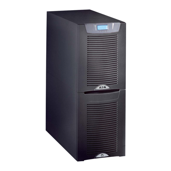
UPSs, each with a CAN Bridge Card and a parallel tie cabinet. Figure 1 shows the Powerware 9155 UPS and an optional Extended Battery Module (EBM). Figure 1. The Powerware 9155 UPS and EBM (2-High Cabinets Shown) ®... - Page 8 INTRODUCTION ® EATON Powerware 9155 Parallel UPS (8–15 kVA) User’s Guide 164201592 Rev C www.powerware.com...
-
Page 9: Safety Warnings
Proper disposal of batteries is required. Refer to your local codes for disposal requirements. Never dispose of batteries in a fire. Batteries may explode when exposed to flame. ® EATON Powerware 9155 Parallel UPS (8–15 kVA) User’s Guide 164201592 Rev C www.powerware.com... - Page 10 Une mise au rebut réglementaire des batteries est obligatoire. Consulter les règlements en vigueur dans votre localité. Ne jamais jeter les batteries au feu. L’exposition aux flammes risque de les faire exploser. ® EATON Powerware 9155 Parallel UPS (8–15 kVA) User’s Guide 164201592 Rev C www.powerware.com...
-
Page 11: Advertencias De Seguridad
Es necesario desechar las baterías de un modo adecuado. Consulte las normas locales para conocer los requisitos pertinentes. Nunca deseche las baterías en el fuego. Las baterías pueden explotar si se las expone a la llama. ® EATON Powerware 9155 Parallel UPS (8–15 kVA) User’s Guide 164201592 Rev C www.powerware.com... - Page 12 SAFETY WARNINGS ® EATON Powerware 9155 Parallel UPS (8–15 kVA) User’s Guide 164201592 Rev C www.powerware.com...
-
Page 13: Ups Setup
NOTE Check the battery recharge date on the packaging label. If the date has expired and the batteries were never recharged, do not use the UPS. Contact your service representative. ® EATON Powerware 9155 Parallel UPS (8–15 kVA) User’s Guide 164201592 Rev C www.powerware.com... -
Page 14: Floor Loading
3-High UPS 3-High UPS with Isolation Transformer 2-High EBM 3-High EBM Clearances The following clearances are recommended for the Powerware 9155 UPS: From Front of Cabinet 36” (91.4 cm) working space From Back of Cabinet 6” (15.2 cm) ® EATON Powerware 9155 Parallel UPS (8–15 kVA) User’s Guide... -
Page 15: Unloading The Cabinet(S)
(see Figure 3). Retain the hardware for later use. NOTE Be sure to retain the stabilizing bracket and hardware for later re-assembly onto the cabinet. ® EATON Powerware 9155 Parallel UPS (8–15 kVA) User’s Guide 164201592 Rev C www.powerware.com... - Page 16 Reinstall the front cover removed in Step 3. Hang the top edge of the cover on the cabinet first, then lower the bottom edge and snap into place. ® EATON Powerware 9155 Parallel UPS (8–15 kVA) User’s Guide 164201592 Rev C www.powerware.com...
- Page 17 With the cabinet supported, slowly pull the pallet away from the cabinet (see Figure 5). Figure 5. Removing the Pallet Roll the cabinet to the desired location. ® EATON Powerware 9155 Parallel UPS (8–15 kVA) User’s Guide 164201592 Rev C www.powerware.com...
- Page 18 UPS SETUP ® EATON Powerware 9155 Parallel UPS (8–15 kVA) User’s Guide 164201592 Rev C www.powerware.com...
-
Page 19: Parallel Installation
Chapter 4 Parallel Installation The Powerware 9155 has the following power connections: 2-phase (L1 and L2), neutral, and ground connection for rectifier/bypass input 2-phase (L1 and L2), neutral, and ground connection for load output The nominal input/output voltages are: 100/200, 110/220, or 120/240 Vac with 180° phase displacement 120/208 or 127/220 Vac with 120°... - Page 20 Follow local requirements. NOTE To accommodate the feature of easy system expandability, it is recommended that initial installation of the Powerware 9155 UPS contain wiring to support the maximum capacity of the UPS cabinet. Switch off utility power to the distribution point where the parallel tie cabinet and UPSs will be connected.
- Page 21 Figure 6. Parallel Tie Cabinet Front Cover Remove the internal cover to gain access to the breakers (see Figure 7). Internal Cover Figure 7. Internal Cover ® EATON Powerware 9155 Parallel UPS (8–15 kVA) User’s Guide 164201592 Rev C www.powerware.com...
- Page 22 Verify that the parallel bypass breaker is in the OFF position (see Figure 8). Mount the parallel tie cabinet to the wall and install the conduit. Figure 8. Parallel Bypass Breaker ® EATON Powerware 9155 Parallel UPS (8–15 kVA) User’s Guide 164201592 Rev C www.powerware.com...
- Page 23 12. Hardwire the UPS input terminations (TB1-1 through TB1-5) for each UPS. See Table 2 for specifications and Figure 10 for a detailed view of the UPS terminal block. ® EATON Powerware 9155 Parallel UPS (8–15 kVA) User’s Guide 164201592 Rev C www.powerware.com...
- Page 24 *Use only 75°C-rated copper wire. Minimum wire size is based on 120/208 full load ratings applied to NEC Code Table 310-16. Input Output Figure 10. UPS Terminal Block ® EATON Powerware 9155 Parallel UPS (8–15 kVA) User’s Guide 164201592 Rev C www.powerware.com...
- Page 25 UPS 1 Line 2 Line 1 UPS 3 Line 2 Figure 11. UPS Output to Parallel Tie Cabinet Wiring 14. Replace each UPS wiring access cover. ® EATON Powerware 9155 Parallel UPS (8–15 kVA) User’s Guide 164201592 Rev C www.powerware.com...
- Page 26 PARALLEL INSTALLATION 15. Hardwire the load to the parallel tie cabinet (see Figure 12). Line 1 Line 2 Neutral Figure 12. Load Connections ® EATON Powerware 9155 Parallel UPS (8–15 kVA) User’s Guide 164201592 Rev C www.powerware.com...
- Page 27 18. Reinstall the internal cover removed in Step 6. 19. Reinstall the parallel tie cabinet front cover removed in Step 5. 20. Continue to “Installing Options” on page 23. ® EATON Powerware 9155 Parallel UPS (8–15 kVA) User’s Guide 164201592 Rev C www.powerware.com...
- Page 28 PARALLEL INSTALLATION Figure 14. Parallel Wiring Diagram ® EATON Powerware 9155 Parallel UPS (8–15 kVA) User’s Guide 164201592 Rev C www.powerware.com...
-
Page 29: Installing Options
Chapter 5 Installing Options This section describes the Powerware Hot Sync CAN Bridge Card. For other options, such as additional X-Slot cards, Powerware LanSafe Power Management Software, remote emergency power-off (REPO), relay output contacts, or programmable signal inputs, refer to the Powerware 9155 UPS (8–15 kVA) User’s Guide. -
Page 30: Powerware Hot Sync Can Bridge Card
INSTALLING OPTIONS Powerware Hot Sync CAN Bridge Card The Powerware Hot Sync CAN Bridge Card, shown in Figure 16, can be installed to provide connectivity for operational mode control and metering of a parallel system at any UPS in the system. - Page 31 INSTALLING OPTIONS If you ordered a factory-configured parallel UPS, remove the Powerware Hot Sync CAN Bridge Card from the X-Slot on the front of the UPS. Retain the screws. Otherwise, remove the X-Slot communication bay cover and retain the screws.
- Page 32 INSTALLING OPTIONS NOTE If you are installing another X-Slot card, be sure to install the Powerware Hot Sync CAN Bridge Card in X-Slot 2. Loosely install the Powerware Hot Sync CAN Bridge Card into an open X-Slot on the front of the UPS. You may want to remove the terminal block from the CAN Bridge Card for better wiring access.
- Page 33 INSTALLING OPTIONS UPS #1 UPS #2 UPS #3 Figure 19. CAN Bridge Card Wiring ® EATON Powerware 9155 Parallel UPS (8–15 kVA) User’s Guide 164201592 Rev C www.powerware.com...
- Page 34 INSTALLING OPTIONS Secure the Powerware Hot Sync CAN Bridge Card with the screws removed in Step 2. On the bottom cover (and also the middle cover if 3-high), remove a knockout tab in the top edge of the cover for each cable: With wire cutters, cut either side of the tab and twist down to remove the tab (see Figure 20).
- Page 35 Figure 21. Reinstalling the Front Covers 12. Continue to “Stabilizing the Cabinet” on page 31 to complete the parallel UPS installation. ® EATON Powerware 9155 Parallel UPS (8–15 kVA) User’s Guide 164201592 Rev C www.powerware.com...
- Page 36 INSTALLING OPTIONS ® EATON Powerware 9155 Parallel UPS (8–15 kVA) User’s Guide 164201592 Rev C www.powerware.com...
-
Page 37: Stabilizing The Cabinet
Chapter 6 Stabilizing the Cabinet NOTE For seismic installations, you MUST order and install a Powerware 9155 UPS seismic kit; do not use the following instructions. NOTE For non-seismic installations, you MUST install the stabilizing bracket on all 3-high cabinets. The stabilizing bracket is optional for 2-high cabinets. - Page 38 “Extended Battery Module Installation” on page 35 to install optional EBMs. “Operation” on page 39 to start up the parallel UPS system. M4 Screws Figure 23. Stabilizing Bracket with One Cabinet ® EATON Powerware 9155 Parallel UPS (8–15 kVA) User’s Guide 164201592 Rev C www.powerware.com...
- Page 39 STABILIZING THE CABINET M4 Screws Figure 24. Stabilizing Bracket with Two Cabinets M4 Screws Figure 25. Stabilizing Bracket with Three Cabinets ® EATON Powerware 9155 Parallel UPS (8–15 kVA) User’s Guide 164201592 Rev C www.powerware.com...
- Page 40 STABILIZING THE CABINET ® EATON Powerware 9155 Parallel UPS (8–15 kVA) User’s Guide 164201592 Rev C www.powerware.com...
-
Page 41: Extended Battery Module Installation
If additional EBMs are installed, plug the EBM cable of the second cabinet into the battery connector on the first EBM. Repeat for each additional EBM. ® EATON Powerware 9155 Parallel UPS (8–15 kVA) User’s Guide 164201592 Rev C www.powerware.com... - Page 42 EBM Battery Circuit Breaker Rear Ground Strap UPS Battery Connector EBM Battery Connector UPS Battery Circuit Breaker Cable Figure 26. Typical EBM Installation (2-High Cabinets Shown) ® EATON Powerware 9155 Parallel UPS (8–15 kVA) User’s Guide 164201592 Rev C www.powerware.com...
- Page 43 NOTE After UPS startup, ensure maximum battery runtime by configuring the UPS for the correct number of EBMs (see page 49). Front Ground Strap Figure 27. Front Ground Strap Installation (2-High Cabinets Shown) ® EATON Powerware 9155 Parallel UPS (8–15 kVA) User’s Guide 164201592 Rev C www.powerware.com...
- Page 44 EXTENDED BATTERY MODULE INSTALLATION ® EATON Powerware 9155 Parallel UPS (8–15 kVA) User’s Guide 164201592 Rev C www.powerware.com...
-
Page 45: Operation
Chapter 8 Operation This chapter contains information on how to use the Powerware 9155, including front panel operation, UPS startup and shutdown, and configuring the UPS for Extended Battery Modules (EBMs). Control Panel Functions The UPS has a four-button graphical LCD with backlight. It provides useful information about the UPS itself, load status, events, measurements, and settings (see Figure 28). -
Page 46: Changing The Language
Display Functions As the default or after 15 minutes of inactivity, the LCD displays the selectable startup screen. The default is the Eaton Powerware logo and can be changed to the Mimic screen in the User Settings menu. The backlit LCD automatically dims after a long period of inactivity. Press any button to restore the screen. - Page 47 UPS Type / Part Number / Serial Number / Firmware / Display / CAN Bridge Turn UPS ON/OFF ON and OFF Options UPS Off / System On / System Off ® EATON Powerware 9155 Parallel UPS (8–15 kVA) User’s Guide 164201592 Rev C www.powerware.com...
-
Page 48: User Settings
<empty> Signal Input must be wired to the CAN Bridge Card (see Figure 19 on page 27). For more information, refer to “Programmable Signal Inputs” in the Powerware 9155 UPS (8–15 kVA) User’s Guide. Serial Port Config Port: [X-Slot-1] [X-Slot-2/Serv]... - Page 49 120V +10% Bypass Voltage Low Limit -1 through -20% (1% increments) 120V -15% Nominal Output Frequency 50 Hz or 60 Hz 60 Hz Synchronization Enabled/Disabled Enabled ® EATON Powerware 9155 Parallel UPS (8–15 kVA) User’s Guide 164201592 Rev C www.powerware.com...
- Page 50 Site Wiring Fault Notice Enabled/Disabled Enabled Reset Custom Event Settings 0 through 32 Total: 0/32 Auto Output Configuration Enabled/Disabled Enabled for initial startup Disabled after initial startup ® EATON Powerware 9155 Parallel UPS (8–15 kVA) User’s Guide 164201592 Rev C www.powerware.com...
-
Page 51: Parallel Ups Startup
UPS. Remove the breaker tie from all battery circuit breakers. Switch all battery circuit breakers to the ON position. indicator stops flashing on each UPS. ® EATON Powerware 9155 Parallel UPS (8–15 kVA) User’s Guide 164201592 Rev C www.powerware.com... - Page 52 Press the button until the Eaton Powerware logo appears. Repeat Steps 6 and 7 for the remaining UPSs in the parallel system. ® EATON Powerware 9155 Parallel UPS (8–15 kVA) User’s Guide 164201592 Rev C www.powerware.com...
- Page 53 If all UPSs appear in the list, press the button until the Eaton Powerware logo appears. If any UPS is missing, verify the Powerware Hot Sync CAN Bridge Card connections and recheck the status from the UPS front panel. 16. Press the button on the front panel display and then press the button to select the TURN UPS ON/OFF menu.
- Page 54 Using the button, scroll to the Measurements menu and press button twice to select the Parallel System menu. Select and view the voltage meter options. 22. Press the button until the Eaton Powerware logo appears. ® EATON Powerware 9155 Parallel UPS (8–15 kVA) User’s Guide 164201592 Rev C www.powerware.com...
-
Page 55: Configuring The Ups For Ebms
UPS-64 models contain 4 strings; EBM-96 models contain 6 strings. Press the button to save the setting. Press the button until the Eaton Powerware logo appears. ® EATON Powerware 9155 Parallel UPS (8–15 kVA) User’s Guide 164201592 Rev C www.powerware.com... -
Page 56: Parallel System Shutdown
Eaton Powerware logo appears. If you want to completely remove power from the UPS, continue to the following section, “Individual UPS Shutdown,” to shut down each UPS. ® EATON Powerware 9155 Parallel UPS (8–15 kVA) User’s Guide 164201592 Rev C www.powerware.com... -
Page 57: Individual Ups Shutdown
Switch off utility power where the UPS is connected. If you are shutting down all the UPSs in a parallel system, repeat Steps 2 through 6 for each UPS then remove utility power. ® EATON Powerware 9155 Parallel UPS (8–15 kVA) User’s Guide 164201592 Rev C www.powerware.com... -
Page 58: Restarting The Parallel System
The UPS goes to Bypass mode for five seconds, and then the indicator illuminates. Each UPS should be in Normal mode. 10. Press the button until the Eaton Powerware logo appears. ® EATON Powerware 9155 Parallel UPS (8–15 kVA) User’s Guide 164201592 Rev C www.powerware.com... -
Page 59: Parallel Bypass
Switch the bypass breaker on the parallel tie cabinet to the ON position. Switch the UPS breakers on the parallel tie cabinet to the OFF position. ® EATON Powerware 9155 Parallel UPS (8–15 kVA) User’s Guide 164201592 Rev C www.powerware.com... - Page 60 On the same UPS front panel, set the UPS to Normal mode: Press the button to select the Go to Normal Mode option. Each UPS should go to Normal mode. ® EATON Powerware 9155 Parallel UPS (8–15 kVA) User’s Guide 164201592 Rev C www.powerware.com...
-
Page 61: Troubleshooting
Chapter 10 Troubleshooting The Powerware 9155 is designed for durable, automatic operation and also alerts you whenever potential operating problems may occur. Usually the alarms shown by the control panel do not mean that the output power is affected. Instead, they are preventive alarms intended to alert the user. - Page 62 If the condition persists, contact your backup time. service representative. Battery circuit breakers are in the OFF Switch all battery circuit breakers to the ON position. position. ® EATON Powerware 9155 Parallel UPS (8–15 kVA) User’s Guide 164201592 Rev C www.powerware.com...
-
Page 63: Silencing The Alarm
Bus option and verify that all UPSs appear in the list. If any UPS is missing, verify the Powerware Hot Sync CAN Bridge Card connections and recheck the status from the UPS front panel. If all UPSs appear in the list, check the pull-chain wiring (see page 26). -
Page 64: Service And Support
Please have the following information ready when you call for service: Model number Serial number Firmware version number Date of failure or problem Symptoms of failure or problem Customer return address and contact information ® EATON Powerware 9155 Parallel UPS (8–15 kVA) User’s Guide 164201592 Rev C www.powerware.com... - Page 66 *164201592C* 164201592 C...
Need help?
Do you have a question about the 9155 and is the answer not in the manual?
Questions and answers