
Related Manuals for Ducati MULTISTRADA 1100 S


Summary of Contents for Ducati MULTISTRADA 1100 S
- Page 1 Libretto uso e manutenzione Use and maintenance manual Manuel d'utilisation et entretien Bedienungs- und Wartungsanleitung...
- Page 2 Use and maintenance manual 1100S 1100...
- Page 4 Ducati Motor Holding S.p.A. cannot accept any liability We are sure that you will use your Ducati for longer journeys for errors that may have occurred in the preparation of as well as short daily trips, but however you use your this manual.
-
Page 5: Table Of Contents
Table of contents Throttle twistgrip 29 Front brake lever Rear brake pedal 31 Gearchange pedal Adjusting the position of the gearchange and rear brake pedals 32 General indications 6 Main components and devices 34 Warranty 6 Symbols 6 Position on motorcycle Useful road safety information 7 Fuel tank filler cap 35 Riding with a full load 8... - Page 6 Vehicle identification number (VIN) 104 by the dealer 87 Label location 105 California evaporation emission system 107 Technical data 88 Ducati limited warranty on emission control system 107 (mm) Overall dimensions Weights 88 Routine maintenance record 110 Fluids and lubricants 89...
-
Page 7: General Indications
General indications Symbols Ducati Motor Holding S.p.A. advises you to read this manual carefully in order to familiarise yourself with your motorcycle. If in doubt, please contact a Ducati Dealer or Authorized Service Centre. You will find the information in the manual useful on trips (which Ducati Motor Holding S.p.A. -
Page 8: Useful Road Safety Information
Useful road safety information Be sure you are clearly visible and avoid riding within the blind spot of a vehicle in front of you. Be very careful at road junctions, or when riding in areas Warning near exits from private land or car parks, or on the slip Read this section before riding your motorcycle. -
Page 9: Riding With A Full Load
Riding with a full load Information on load capacity The total weight of the motorcycle in running order with Your motorcycle is designed for travelling over long rider, luggage and additional accessories should not distances with a full load in complete safety. exceed 410 kg. - Page 10 Do not insert objects into gaps in the frame, where they could interfere with moving parts. When fitting panniers (available from the Ducati parts service): arrange personal effects and accessories according to weight and distribute them evenly in both panniers;...
-
Page 11: Identification Data
Identification data All Ducati motorcycles have two identification numbers, one for the frame (fig. 2) and one for the engine (fig. 3). Frame number Engine number Notes These numbers indicate the motorcycle model and should be quoted when ordering spare parts. -
Page 12: Controls
Controls Warning This section shows the position and function of the controls used to drive the motorcycle. Be sure to read this information carefully before you use the controls. Position of the motorcycle controls (fig. 4) 1) Instrument panel. 2) Key-operated ignition switch and steering lock. 3) Left-hand handlebar switch. -
Page 13: Instrument Panel
The related menus are for use by trained personnel only. If you accidentally access this function, turn the key to OFF and have the motorcycle inspected at an authorized Ducati Service Centre. 4) Tachometer (rpm). Indicates engine revs per minute. -
Page 14: Lcd - Main Functions
LCD – Main functions 4) Auxiliary display. Displays, in sequence: total distance travelled, trip distance travelled, fuel trip counter, average speed, current fuel Warning consumption, average fuel consumption, remaining range. Any adjustments to the instrument panel must only be carried out when the motorcycle is stationary. Never operate 5) EOBD light (amber). - Page 15 6) Turn indicator light (green). Flashes when a turn signal is on. 7) Engine oil pressure light (red). Illuminates when engine oil pressure is too low. This light must illuminate when ignition is switched to ON and must go out a few seconds after the engine starts. It may illuminate briefly when the engine is very hot, however it should go out as the engine revs up.
-
Page 16: Lcd - How To Set/Display Parameters
LCD – How to set/display parameters When the engine is started (key from OFF to ON or Key-ON) the instrument panel performs a Check of all the instrumentation: dials, display and indicators (fig. 7). CHECK 1 km/h miles km/L mpgal CHECK 2 km/h fig. - Page 17 (fig. 8) Oil temperature indicator Gives engine coolant temperature. If the engine oil temperature is below or equal to +39 °C / 102.2 °F, “LO” flashes on the display. If the temperature is between +40 °C/104 °F and +170 °C/ DATA FLASHING DATA FLASHING 338 °F, the numerical value will be shown on the display.
- Page 18 Clock setting Press button (A, fig. 5) for 2 seconds. “AM” flashes. Press button (B, fig. 5), to switch to “PM”. Press button (B) again to return to “AM”. Press button (A) to confirm selection and enter the hours setting mode. The hour digits flash. Set hours using the button (B).
- Page 19 (fig. 10) Odometer function Indicates the total distance travelled. (fig. 10) Trip counter function Indicates the distance travelled since last reset. The trip counter can be reset at any time by accessing the relative display function and pressing button A fig. 5for at least 2 seconds.
- Page 20 (fig. 11) Current fuel consumption function When the motorcycle is in motion with the engine running the display will show a numerical value corresponding to the current fuel consumption. If the motorcycle is stopped with the engine running the display will show fixed lines “- -. -”. With the engine stopped and the motorcycle at a standstill the display shows “0.0”.
- Page 21 (fig. 12) Remaining range function Displays how many kilometres or miles the motorcycle can travel on the remaining fuel. When the motorcycle is stationary, or stationary with the engine running, the latest value to be recorded will remain on the display until it is updated.
-
Page 22: Display Backlight
Display backlight Notes The instrument panel backlight is switched on only if When the engine is started, the system turns off the the parking lights or low/high beam is on. headlights and only turns them back on again when the In this case the instrument panel, using sensors that engine has started or when the starter button is released measure ambient temperature and light intensity,... -
Page 23: The Immobilizer System
The immobilizer system Warning For additional anti-theft protection, the motorcycle is The red key (A) has a rubber sleeve to keep it in perfect equipped with an IMMOBILIZER, an electronic system condition, and prevent contact with other keys. Never that locks the engine automatically whenever the ignition remove this protection unless absolutely necessary. -
Page 24: Code Card
Warning Sharp knocks can damage the electronic components inside the key. Notes The three keys have a small tag (1) attached, which shows their identification number. Warning Keep the keys separate, and store the tag (1) and key A in a safe place. It is also recommended to use always the same black key to start the motorcycle. -
Page 25: Procedure To Override The Immobilizer Using The Throttle Twistgrip
Procedure to override the immobilizer 5) When you release the throttle grip, if the code has been entered correctly the following two cases may occur: using the throttle twistgrip A) the EOBD light starts flashing to indicate that engine starting is now enabled. The light switches off 1) Turn the key to ON, then turn the twistgrip to fully open after 4 seconds, or if engine speed exceeds the the throttle and hold it open. -
Page 26: Duplicate Keys
(up to a maximum of 8 keys) (3, fig. 5) on the instrument panel will flash briefly. DUCATI Service may ask for proof that you are the legitimate This means that the immobilizer system has owner of the motorcycle. -
Page 27: Ignition Switch And Steering Lock
Ignition switch and steering lock (fig. 16) The ignition switch is located in front of the top yoke. The switch has four positions. A) ON: enables lights and engine operation; B) OFF: disables lights and engine operation; C) LOCK: steering locked; D) P: parking light on and steering locked. -
Page 28: Left-Hand Handlebar Switch
Left-hand handlebar switch (fig. 17) 1) Two-position light selector switch: - position = low beam headlight on; - position = high beam headlight on. 2) Switch = 3-position turn signal: - centre position = off; - position = left turn; - position = right turn. -
Page 29: Clutch Lever
Clutch lever (fig. 18) The clutch lever (1) is fitted with a span adjuster (2) which serves to alter the distance of the lever from the handlebar. To make the adjustment, keep the lever (1) fully forward and turn the wheel (2) to one of the four preset positions. Note that: position n°... -
Page 30: Right-Hand Handlebar Switch
Right-hand handlebar switch Throttle twistgrip (fig. 19) (fig. 19) The twistgrip (3) on the right handlebar opens the throttles. 1) ENGINE STOP switch, with two positions: When released, the twistgrip returns automatically to - position (RUN) = run; the initial position (idling speed). - position (OFF) = stop engine. -
Page 31: Front Brake Lever
Front brake lever (fig. 20) Pull the lever (1) towards the twistgrip to operate the front brake. The system is hydraulically assisted and you only need to pull the lever gently. The brake lever has a wheel (2) for adjusting the distance between lever and twistgrip on the handlebar. -
Page 32: Rear Brake Pedal
Rear brake pedal (fig. 21) Push down on the pedal (1) with your foot to operate the rear brake. The brake system is hydraulic and very little force is required to operate it. fig. 21 Gearchange pedal (fig. 22) The gear change pedal is at rest when in centre position N, and automatically returns to the centre position. -
Page 33: Adjusting The Position Of The Gearchange And Rear Brake Pedals
Adjusting the position of the gearchange and rear brake pedals The position of the gearchange and rear brake pedals in relation to the footrests can be adjusted to suit the requirements of the rider. Proceed as follows to change the pedal position: (fig. - Page 34 (fig. 24) Rear brake pedal Loosen the locknut (5). Turn the pedal travel adjustment bolt (6) until the pedal is in the desired position. Tighten the locknut (5). Operate the pedal by hand to check that there is 1.5 to 2 mm of freeplay before the brake bites If not, adjust the length of the master cylinder pushrod as follows.
-
Page 35: Main Components And Devices
Main components and devices Position on motorcycle (fig. 25) 1) Fuel tank filler cap 2) Passenger seat lock and helmet holder. 3) Document compartment lock. 4) Side stand. 5) Front fork adjusters. 6) Rear shock absorber adjusters. 7) Rear view mirrors. 8) Silencer and exhaust pipes. -
Page 36: Fuel Tank Filler Cap
Fuel tank filler cap (fig. 26.1) Opening Raise the cover (1) and insert the key into the lock. Give the key a 1/4 turn clockwise to unlock. Raise the cap (2, fig. 26.2). Closing Close the cap (2) with the key inserted and press it into its seat. -
Page 37: Passenger Seat Lock And Helmet Holder
Passenger seat lock and helmet holder (fig. 27) Opening Insert the key into the seat lock (1) and turn it clockwise OPEN until the seat catch disengages with an audible click. Lift the rear of the seat (2) and slide it backwards off the front mountings. -
Page 38: Document Compartment Lock
Document compartment lock To open the cover of the document compartment, insert the OPEN key in the lock (1) and turn it anti-clockwise to release the catches (fig. 29.1). Open the cover (fig. 29.2) of the document compartment to access the user’s manual and the toolkit (see page 54). Important Do not use this compartment to hold heavy or metal objects that might move about while the motorcycle is in... -
Page 39: Sidestand
Sidestand Notes (fig. 30) You can only start the engine with the sidestand extended if the gearbox is in neutral. Important Before lowering the side stand, make sure that the supporting surface is hard and flat. Do not park on soft ground, gravel or on asphalt softened by the sun etc. -
Page 40: Front Fork Adjuster
Front fork adjuster The front fork can be adjusted in rebound, compression and preload. The settings are adjusted by way of external adjuster screws: 1) to adjust rebound damping (fig. 31.1 and fig. 31.2); 2) to adjust inner spring preload (fig. 31.1 and fig. 31.2); 3) to adjust compression damping (fig. - Page 41 Start from this position and turn the adjuster anti- clockwise while counting the number of clicks, which correspond to position 1, 2 and so forth. The STANDARD factory settings are as follows: 1100S compression: 9 clicks; rebound: 12 clicks. Spring preload: 10 mm (10 turns, from fully unscrewed, 1 turn = 1 mm).
-
Page 42: Rear Shock Absorber Adjusters
Rear shock absorber adjusters (fig. 33.1, fig. 33.2, fig. 34.1 and fig. 34.2) The shock absorber has external adjusters that enable you to adjust the suspension to suit the load on the motorcycle. The adjuster (1) located on the right-hand side, where the lower end of the shock absorber is attached to the swingarm, controls rebound damping. - Page 43 1100 STANDARD rebound damping setting (1): screw the adjuster fully in (clockwise), then screw it out 18 clicks. STANDARD compression damping setting (2): screw the adjuster all the way in (clockwise), then screw it out by 2 turns. The preload on the outer spring of the shock absorber can be adjusted by way of the knob (3) located on the right-hand side of the frame;...
-
Page 44: Rear View Mirror Adjustment
Rear view mirror adjustment Simply push or pull the outside of the mirrors in the required direction to obtain optimum visibility (fig. 35.1). Tighten the screw at the bottom of the mounting to lock the mirror in the required position (fig. 35.2). Warning Never attempt to adjust the position by moving the whole mirror assembly, as this could break it. -
Page 45: Adjusting The Rear Ride Height
Adjusting the rear ride height The rear ride height is the result of tests carried out under different riding conditions by our technical staff. Modifying this parameter is a very critical operation, and can be dangerous if carried out by untrained persons. Before changing the standard setting, measure the reference value (H, fig. - Page 46 The maximum distance that the UNIBALL end fitting (A) can be unscrewed from the tie-rod body is 5 threads, or 7.5 mm (B). fig. 37...
-
Page 47: Riding The Motorcycle
Riding the motorcycle For the first 100 km, use the brakes gently. Do not brake violently or keep brake applied for too long. This will enable a correct break-in of friction material on brake pads against brake discs. To allow all the mechanical moving parts in the motorcycle to adapt to one another, and to avoid shortening the life of the main engine components, it is advisable to avoid sudden acceleration and running the engine at high rpm for too long,... - Page 48 Throughout the running-in period, be careful to stick to the recommended maintenance schedule and periodic service intervals indicated in the warranty booklet. Failure to follow these instructions releases Ducati Motor Holding S.p.A. from any liability whatsoever for any engine damage or shorter engine life.
-
Page 49: Pre-Ride Checks
Fuel level in the tank In case of malfunctioning, do not start the motorcycle Check the fuel level in the tank. Re-fuel if necessary and call a DUCATI Dealer or Authorized Workshop. (page 53). Engine oil level Check the oil level in the sump through the sight glass. -
Page 50: Starting The Engine
Starting the engine Warning Before starting the engine, familiarise yourself with the controls that you will use when riding (see page 11) 1) Turn the ignition switch to ON (fig. 39). Check that both the green light N (8, fig. 6) and the red light (7, fig. - Page 51 2) Check that the stop switch (1, fig. 40) is positioned (RUN), then press the starter button (2). This model has servo-assisted starting. To use the servo-assisted starting feature, press the start button (2) and release it immediately. When you press the button (2) the starter motor operates automatically for a maximum time determined by the engine temperature.
-
Page 52: Moving Off
Moving off Braking Slow down in time, change down to use the engine brake, 1) Disengage the clutch by squeezing the control lever. then apply both brakes. Pull the clutch lever before stopping 2) Push down the gearchange lever firmly with the tip of the motorcycle, to avoid sudden engine stop. -
Page 53: Stopping The Motorcycle
Stopping the motorcycle Important Reduce speed, shift down and release the throttle twistgrip. Do not leave the key at P for long periods or the Change down to engage first gear and then neutral. Apply battery will run down. Never leave the motorcycle the brakes and bring the motorcycle to a complete stop. -
Page 54: Refuelling
Refuelling (fig. 41) Max level Do not overfill the tank when refuelling. The fuel level should always be below the rim of the filler recess. Warning Use fuel with low lead content and an original octane number of 95 minimum (see table “Fluids and lubricants” on page 89). -
Page 55: Toolkit And Accessories
Toolkit and accessories (fig. 42) A compartment in the right-hand fairing, accessible by opening the access cover (see page 37), houses: the use and maintenance manual; the helmet fastening cable; the toolkit including (fig. 43): - spark plug wrench; - Tommy bar for spark plug wrench; - double-bit screwdriver. -
Page 56: Main Use And Maintenance Operations
Main Use and Maintenance Operations Removing the fairing panels Some parts of the motorcycle fairing have to be removed for certain maintenance or repair operations. Warning If parts that have been removed are not refitted correctly they may become loose suddenly while riding and cause you to lose control of your motorcycle. - Page 57 Movable nose fairing Unscrew the four screws (1) securing the movable headlight fairing to the brackets with the seal (2). Remove the movable headlight fairing complete with the windshield (fig. 44). To replace the windshield, use the special torx wrench to unscrew the screws (3) and nylon washers (4), while holding the rubber coated nuts (5) in position from the inside the fairing (fig.
- Page 58 Fixed nose fairing Unscrew the six screws (1) securing the inside panel to both sides of the fixed headlight fairing and lift the fairing off (fig. 46). Notes When removing the shroud take care not to damage the paintwork of the fairing. Unscrew the six screws (2) securing the fixed headlight fairing to the headlight bracket (fig.
- Page 59 Left half fairing Starting on the left, from inside the fairing, turn the quick release fastener (1) 1/4 of a turn anti-clockwise to release the front of the left half fairing (fig. 48). To release the rear of the left half fairing, pull the stop (2) all the way out at the frame bracket: to facilitate this operation, push the side fairing in from the outside at the stop (fig.
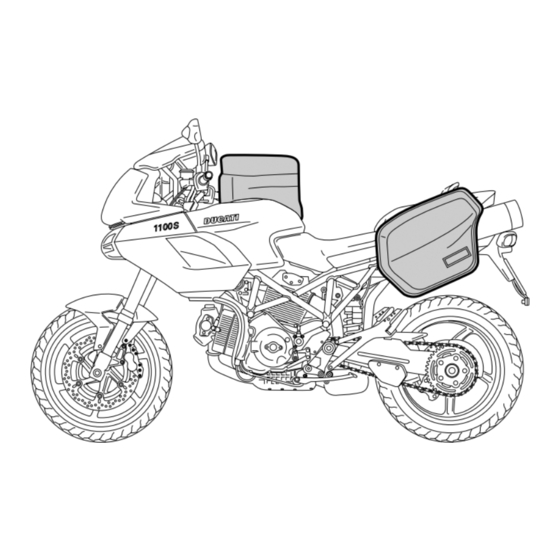
- Page 60 1/4 of a turn clockwise. Panniers The motorcycle has provision for fitting side panniers. The pannier kit is available from the Ducati parts service. As well as all the parts necessary for fitting, the kit also contains an instruction booklet.
-
Page 61: Checking The Brake And Clutch Fluid Level
Brake and clutch fluid must be topped up and changed at the intervals specified in the routine maintenance table (see Warranty Card) by a Ducati Dealer or Authorized Workshop. Important It is recommended that all brake and clutch hoses be renewed every four years. - Page 62 If the control lever has excessive play and the transmission snatches or jams when engaging a gear, then there is 3 mm (MAX) 3 mm probably air in the circuit. Contact a Ducati Dealer or Authorized Workshop, who will check the system and bleed the circuit. Warning...
-
Page 63: Checking The Brake Pads For Wear
The rear brake pads must be replaced when about 1 mm of friction lining (fig. 55) is still visible through the opening in the calipers. Important Have the brake pads replaced at a Ducati Dealer or Authorized Workshop. fig. 54 1 mm... -
Page 64: Lubricating Cables And Joints
Ducati Dealer or Authorized Service Centre. To prevent failure open the throttle control by unscrewing the two fastening screws (1, fig. 56) then grease the cable ends and the pulley with SHELL Advance Grease or Retinax LX2. -
Page 65: Adjustment Of The Throttle Cable Free Play
Adjustment of the throttle cable free play 1,5 ÷ 2 mm The throttle twistgrip should have free play of 1.5 to 2.0 mm (fig. 58) (measured in terms of twistgrip rotation) in all 1,5 ÷ 2 mm steering positions. If this is not the case, adjust the cable by means of the adjusters (1) on the throttle body (fig. -
Page 66: Charging The Battery
Charging the battery (fig. 60) Before charging the battery, it is best to remove it from the motorcycle. Remove the left half fairing (see page 58). Always disconnect the black negative terminal (-) first, and then the red positive terminal (+). Unscrew the two screws (1) securing the battery brackets and remove the battery from the battery compartment. -
Page 67: Checking The Chain Tension
If it is not, adjust the chain tension accordingly. Important 38 ÷ 42 mm Have the chain tensioned at a Ducati Dealer or Authorized Workshop. fig. 61 Warning Correct tightening of the swingarm bolts (1, fig. 62) is essential to rider and passenger safety. -
Page 68: Lubricating The Drive Chain
Lubricating the drive chain The chain fitted on your motorcycle has O-rings that keep dirt out of and lubricant inside the sliding parts. So as not to damage these seals when cleaning the chain, use special solvents and avoid aggressive washing with high-pressure steam cleaners. -
Page 69: Changing The High And Low Beam Headlight Bulbs
Changing the high and low beam headlight bulbs Before replacing a burnt-out bulb, make sure that the new one matches the voltage and wattage specifications in the “Electrical System” paragraph on page 96. Always check that the new bulb works before refitting removed parts. Figure fig. - Page 70 Low beam headlight (top bulb) Disconnect the wiring connectors (4) from the bulb. Press then squeeze the ends of the spring (5) to detach it from the bulb holder (fig. 65). Lift the spring (5). Remove the old bulb (6) and fit the new one, taking care not to touch the glass (fig.
- Page 71 Notes for the USA version: To remove the low beam headlight bulb (7), detach the LOCK LOCK connector (A) from the wiring, then turn the bulb counter- clockwise to remove it (fig. 67). Replace with a bulb of equal rating. When fitting the new bulb, turn it clockwise to lock it in the holder.
- Page 72 Remove the old bulb (10) and fit the new one, taking care not to touch the glass (fig. 69). Parking light Disconnect the wiring connectors (11) from the terminals (fig. 70). Remove the side light bulb (12) from its holder and fit a new one of the same type.
-
Page 73: Changing The Front Turn Indicator Bulbs
Changing the front turn indicator bulbs The front turn signals are integrated in the rear view mirrors. To replace the bulb, unscrew the screw (1) and remove the lens (2) of the indicator from the mirror (fig. 71). The bulb (3) is of the bayonet-type: press and twist anti- clockwise to remove. -
Page 74: Changing The Rear Turn Indicator Bulbs
Changing the rear turn indicator bulbs To change the rear turn indicator bulbs, rotate the indicator body (1) by a quarter of a turn so that the lens is facing upwards, and extract it from indicator support (fig. 73). The bulb (2, fig. 74) is of the bayonet type: push it in and turn it anti-clockwise to remove it. -
Page 75: Changing The Number Plate Light And Brake Light Bulbs
Changing the number plate light and brake light bulbs Unscrew the two screws (1) securing the rear light mounting to the number plate holder on the inside of the holder. Unscrew the screw (2) and slightly withdraw the rear light support (fig. 75). Disconnect the connector (A) of the rear wiring harness and remove the rear light mounting (fig. - Page 76 Unscrew the two self-tapping screws (3) securing the shell (4) and the number plate light lens. Remove the shell and the lens and change the number plate light bulb (5) (fig. 77). To change the brake light bulb, proceed as above and also remove the brake light lens (6) from its support.
-
Page 77: Headlight Aim
Headlight aim (fig. 79) To check the headlight aim, place the motorcycle upright with the tyres inflated to the correct pressure and one person sitting astride the motorcycle. The motorcycle should be perfectly vertical, with its longitudinal axis at right angles to a wall or screen at a distance of 10 metres. - Page 78 (fig. 80) Headlight vertical adjustment The vertical alignment of the headlamp can be adjusted manually by turning the screw (1). Horizontal alignment can be adjusted by turning screw (2). Notes To access the headlight adjuster screws, remove the fixed headlight fairing. Important Screws (1) and (2) have no travel limit.
-
Page 79: Tubeless Tyres
After replacing a tyre, the wheel must be balanced. Important Do not remove or alter the position of the wheel balancing weights. Notes If tyres need changing, contact a Ducati Dealer or Authorized Service Centre to make sure wheels are removed and refitted correctly. - Page 80 Minimum tread depth Measure the tread depth (S, fig. 81) at the point where the tread is most worn. It should not be less than 2 mm, and in any case not less than the legal limit. Important Visually inspect the tyres at regular intervals for cracks and cuts, especially on the side walls, and bulges or large stains that indicate internal damage.
-
Page 81: Checking The Engine Oil Level
Replace the filler cap. Important Engine oil and oil filters must be changed by a Ducati Dealer or Authorized Workshop at regular intervals, as specified in the routine maintenance chart (see Warranty Card). fig. 82... -
Page 82: Cleaning And Renewing The Spark Plugs
Spark plug condition provides a good measure of engine condition. Have the spark plugs inspected or replaced at a Ducati Dealer or Authorized Workshop. Firstly, they will check the colour of the ceramic insulator of the central electrode: an even brown colour is a sign that the engine is in good running order. -
Page 83: General Cleaning
General cleaning Warning To preserve the original shine on metal surfaces and There may be loss of braking efficiency immediately paintwork, wash and clean your motorcycle at regular after washing the motorcycle. Never grease or lubricate intervals depending on the type of use and according the brake discs as this would cause loss of braking to the particular road conditions. -
Page 84: Storing The Motorcycle
Periodically carry out the required checks and renew parts as pour a few drops of engine oil into the cylinders through the necessary, using Ducati original spare parts, in compliance spark plug seats, then crank the engine by hand a few times with the regulations in the country concerned. -
Page 85: Maintenance
Maintenance Programmed maintenance plan: operations to be carried out by the dealer km x1000 List of operations with frequency miles x1000 22.5 37.5 (distance or time interval*) Months • • • • • • Change the engine oil • • •... - Page 86 km x1000 List of operations with frequency miles x1000 22.5 37.5 (distance or time interval*) Months • • • • • • Check the brake and clutch fluid levels • Change the clutch and brake fluid • • • • •...
- Page 87 km x1000 List of operations with frequency miles x1000 22.5 37.5 (distance or time interval*) Months • • • • • Check the front sprocket retaining bolts • • • • • General lubrication and greasing • • • • •...
-
Page 88: Programmed Maintenance Plan: Operations To Be Carried Out By The Dealer
Programmed maintenance plan: operations to be carried out by the dealer km x1000 List of operations with frequency miles x1000 (distance or time interval*) Months • Checking the engine oil level • Check the brake and clutch fluid levels • Check tyre pressure and wear •... -
Page 89: Technical Data
Technical data Overall dimensions (mm) (fig. 84) 1462 Weights 2130 Dry weight in riding order without fuel: 196 kg. Fully laden: 850,4 410 kg. Warning Failure to observe weight limits could result in poor handling and impair the performance of your motorcycle, and could result in loss of control. -
Page 90: Fluids And Lubricants
Fluids and lubricants Type (litres) Fuel tank, including a reserve of 3 dm (litres) Unleaded fuel with 95 fuel octane rating (at least) Lubrication circuit SHELL - Advance Ultra 4 Front/rear brake and clutch circuits Special hydraulic system fluid — SHELL Advance Brake Dot 4 Protection for electrical contacts SHELL - Advance Contact Cleaner spray for... -
Page 91: Engine
(fig. 85) Engine Desmodromic timing system 90 degree twin cylinder four stroke, 1100 cc, Desmodromic 1) Opening (or upper) rocker arm; valve gear, electronic fuel injection, air cooled. 2) opening shim; Bore (mm): 3) half rings; 4) closing (or lower) shim; Stroke (mm): 5) return spring for closing rocker;... -
Page 92: Performance Data
Performance data Exhaust system Maximum speed in any gear should be reached only Equipped with catalytic converter in compliance with Euro 3 after the correct running-in period with the motorcycle emission regulations. properly serviced at the recommended intervals. Spark plugs Ignition is provided by two spark plugs per cylinder. -
Page 93: Transmission
17/30 competitive trials, you may refer to Ducati Motor 20/27 Holding S.p.A. who will be glad to provide information 22/24 about the special ratios available. Contact a Ducati Dealer 24/23 or Authorized Workshop. 28/24 Warning For replacement of the rear sprocket, contact a Ducati Dealer or Authorized Workshop. -
Page 94: Brakes
Brakes Rear With fixed drilled steel disc. Flange material: Front steel. With double semi-floating drilled disc. Braking surface material: Flange material: steel. steel. Disc diameter: Braking surface material: 245 mm. steel. Hydraulically operated by pedal on R.H. side. Disc diameter: Braking surface: 320 mm. -
Page 95: Frame
Frame Tyres High-strength tubular steel trellis frame. Steering angle (on each side): Front 35° Radial tubeless tyre Size: Steering geometry is as follows: 120/70-ZR17 Steering head rake: 24° Rear Trail: Radial tubeless tyre 92 mm. Size: 180/55-ZR17 Wheels Front Six spoke, light alloy front wheel. Dimensions: MT3.50x17". -
Page 96: Suspension
Suspension Available colours Front 1100S Hydraulic upside-down fork provided with outer adjuster Ducati anniversary red code no. 473.101 (PPG); for rebound, compression, and preload (for inner springs Transparent, 228.880 (PPG); of fork legs). red frame with black wheels. Stanchion diameter: 43 mm. -
Page 97: Electrical System
Electrical system The main components of the electrical system are: Front headlight with two vertically arranged halogen lamps, consisting of the following: low beam unit H7 (12V-55W); high beam unit H7 (12V-55W) for EU and UK - H9 (12V-65W) for USA; parking light 12V-6W. - Page 98 Fuses The main fuse box (1, fig. 86) is located under the left side fairing (see page 58). Remove the protective cover to access the fuses. In addition to the fuses in the main fuse box, other fuses are located alongside the battery. Two fuses (2, fig.
- Page 99 Remove the protective cap (A, fig. 88) to expose the fuses. A blown fuse is identified by a broken inner filament (5, fig. 89). Important Switch the ignition key to OFF before replacing the fuse to avoid possible short circuits. Warning Never use a fuse with a rating other than that specified.
- Page 100 Key to the electrical system/injection system 30) Sidestand switch diagram 31) Neutral switch 32) Oil pressure switch 1) Right-hand handlebar switch 33) Rear brake light switch 2) Key switch 34) Stepper motor 3) Fusebox 35) Ignition/injection unit 4) Fuses 36) Clutch switch 5) Starter motor 37) Front brake light switch 6) Starter contactor...
- Page 101 Wire colour coding Key to the fusebox B Blue W White Pos. Device Val. V Violet Bk Black Key on 10 A Y Yellow R Red Lights 15 A Lb Light blue Horn, brake light, passing 15 A Gr Grey G Green Instrument panel Bn Brown...
-
Page 102: For United States Of America Version Only
Carbon motor vehicle safety from the Hotline. monoxide does not react in the same way, but is toxic. Ducati utilizes lean carburetor settings and other systems to reduce carbon monoxide and hydrocarbons. Safety warnings Traffic Rules vary from jurisdiction to jurisdiction. -
Page 103: Tampering Warning
Problems that may affect motorcycle emissions escape of fuel vapors from the throttle body and fuel tank. If you are aware of any of the following symptoms, have the vehicle inspected and repaired by your local Ducati dealer. Symptoms: Tampering warning Hard starting or stalling after starting. -
Page 104: Riding Safety
Riding safety When the roadway is wet, rely more on the throttle to control vehicle speed and less on the front and rear brakes. The points given below are applicable for every day The throttle should also be used judiciously to avoid skidding motorcycle use and shoud be carefully observed for safe and the rear wheel from too rapid acceleration or deceleration. -
Page 105: Protective Apparel
Ducati does not manufacture sidecars or trailers and cannot predict the effects of such accessories on handling or stability, but can only warn that the effects will be adverse... -
Page 106: Label Location
Label location (fig. B) fig. B... - Page 107 Tensione catena (sul cavalletto laterale) Chain tension adjustment (on side stand) TO HORIZONTAL MANIFOLD TO VERTICAL MANIFOLD WARM AIR INLET 6 (Only Canada)
-
Page 108: California Evaporation Emission System
1) Warn air inlet; Ducati North America, Inc., 10443 Bandley Drive, Cupertino, 2) Canister; California, 95014 warrants that each new 1998 and later Ducati 3) Dell’Orto jet; motorcycle, that includes as standard equipment a headlight, 4) Intake manifolds;... - Page 109 The owner may be required to sale or use of or inability to use the Ducati motorcycle for any keep receipts and failed parts in order to receive purpose.
- Page 110 Some states do not allow limitations on how long an implied warranty lasts so the above limitation may not apply to you. C. No dealer is authorized to modify this Ducati Limited Emission Control Systems Warranty. IV. Legal rights This warranty gives you specific legal rights, and you may also have other rights which vary from state to state.
-
Page 111: Routine Maintenance Record
Routine maintenance record Km/mi Ducati Mileage Date Service Name 1,000/600 12,000/7,500 24,000/15,000 36,000/22,500 48,000/30,000 60,000/37,500... - Page 112 Ducati Motor Holding spa via Cavalieri Ducati, 3 40132 Bologna, Italia Tel. +39 051 6413111 Fax +39 051 406580 www.ducati.com...
- Page 113 STARTER ENGINE STOP BW Bk G/Bk FREE LOCK PUSH PARK R/Bk Y Y Y V/Bk 30 A B/Bk P/Bk R/Bk 10 W 1N4007 W/Bk ON USA VERSION H9-12V/65W ON EU UK VERSION H7-12V/55W 5/21 W Gr/R Y/Bk 12V/55W n.c. n.c. n.c.