SATO CL608e Operation Manual
Hide thumbs
Also See for CL608e:
- Operator's manual (103 pages) ,
- Adjustment (16 pages) ,
- Programming reference manual (290 pages)
Table of Contents
Advertisement
Advertisement
Table of Contents

Related Manuals for SATO CL608e


Summary of Contents for SATO CL608e
- Page 1 CL608e/612e Printers Operation Manual Issued December 2000...
-
Page 2: Sato Group Of Companies
All rights reserved. This document, nor any part of it, may be reproduced or issued to third parties in any form without the express permission of SATO Europe. The material in this document is provided for general information only and is subject to change without... - Page 3 SATO supplier. SATO Europe N.V. makes no guarantee that all the features described in this manual are available in all models, and, due to SATO’s policy of continuous development and improvement, spec-...
-
Page 4: Warranty And Copyright
Warranty and Copyright SATO Europe N.V. makes no guarantee of any kind with regard to this material, including, but not limited to, the implied guaranties of merchantability and fitness for a particular purpose. -
Page 5: Table Of Contents
Contents 1. Specifications ................. 1 2. Introduction ..................3 Installation Considerations ..........3 Ribbon ................3 Dimensions ................. 4 Operator Panel ..............5 Rear Panel ................7 Switches And Sensors ............8 Computer Connections ............9 2.7.1 Bi-directional parallel interface (standard) ....9 2.7.2 Optional interface (RS-232C) ......... - Page 6 Troubleshooting Tables ............. 37 Print Quality Problems ............38 6. Cleaning and Maintenance ............41 Introduction ............... 41 Cleaning the Print Head, Platen and Rollers ....42 Cleaning the Label Sensor Unit ........46 Appendix A Advanced Settings ............47 Appendix B Declaration of Conformity ..........
-
Page 7: Specifications
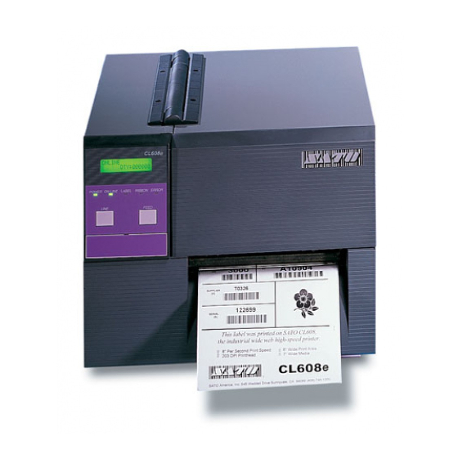
Operation Manual 1. Specifications Specifications The major difference in the CL608e and the CL612e printers is the resolution of the Print Head. The CL608e with its 203 dpi Print Head provides an economical labeling solution for most applica- tions. The CL612e provides a higher print resolution, 305 dpi, to give laser quality printing. - Page 8 Operating: +5 ~ +40°C, humidity 30 ~ 80% RH non-condensing Storage: -5 ~ +60°C, humidity 30 ~ 90% RH non-condensing Approvals CE, TÜV-GS, UL, CSA Options Rotary Cutter, Dispenser with External Backing Paper Rewinder, External Label Rewinder R610, Memory Expansion, Keyboard, Real Time Clock CL608e/612e...
-
Page 9: Introduction
2.2 Ribbon Use only SATO thermal transfer ribbons which were formulated expressly for use in all SATO printers. Use of other than approved ribbons may result in unsatisfactory print quality and/or damage to the print head and may void your warranty. -
Page 10: Dimensions
2. Introduction Operation Manual 2.3 Dimensions NOTE: The exact position of components may vary, depending on the model. High Depth Printer Footprint Width Depth High Standard 355mm 429mm 299mm With dispenser 355mm 545mm 299mm With cutter 355mm 460mm 299mm CL608e/612e... -
Page 11: Operator Panel
After you power on the printer, familiarize yourself with the keys and indicators, as it will help you understand the configuration process. Display: LCD display for: • printer status (error messages) • Printer setup • Quantity • Offline CL608e/612e... - Page 12 Turning it all the way counter- clockwise (plus offset) should move the print position down 2.0mm. Affects stop position of label feed, print position and dispense posi- tion. DISPLAY (VR4): Display contrast CL608e/612e...
-
Page 13: Rear Panel
USB, Twinax/Coax, RS422/485, RS232C up to 19200bps and Standard Par- allel. EXT: External signal connector. Memory Card Slot: Optional for PCMCIA cards. Memory Card Slot Modular Interface Fan-Fold Power Opening Switch Fuse Backing Take Up Opening AC in CL608e/612e... -
Page 14: Switches And Sensors
Label Sensor Unit: This sensor unit contains two types of sen- sors, one for label gap (movable, 25 - 90mm from the inner label edge)) and one for I-Mark sensing (fixed). Ribbon Motion Sensor Label Sensor Unit CL608e/612e... -
Page 15: Computer Connections
2. Be sure to use a IEEE 1284 compatible cable. Connector: 36 PIN Amp Max. Cable length: 1,8 m Centronic 5 m IEEE 1284 Wire Connection Table for IEEE 1284 compatible cable: Host Printer Host Printer Strobe Error Init Select in Busy Select Shield Shield CL608e/612e... -
Page 16: Optional Interface (Rs-232C)
2. Interface Cable The wire connection varies depending on the communication product. Prepare an appropriate cable for the communication protocol. Connector: DSUB-25S. Cable length: Less than 5 meters. ER Control Status 3/4 CL608e/612e... -
Page 17: Optional Interface (Usb)
2. Interface Cable Please use a cross-cable when you connect one printer to one computer. If you connect a printer to a HUB, please use a straight cable. CL608e/612e... - Page 18 2. Introduction Operation Manual This page is intentionally left blank. CL608e/612e...
-
Page 19: Printer Configuration
To set the switches, first power the unit Off, then position the DIP switches. After placing the switches in the desired positions, power the printer back on. The switch settings are read by the printer electronics during the power up sequence. They will not become effective until the power is cycled. CL608e/612e... -
Page 20: Rs232 Transmit/Receive Setting
Selects the number of stop bits to end each byte. DSW1 DSW1-4 SETTING 1 Stop Bit 2 Stop Bits Baud Rate Selection (DSW1-5, DSW1-6) Selects the data rate(bps) for the RS232 port. DSW1 DSW1-5 DSW1-6 SETTING 9600 19200 38400 57600 * Factory Default CL608e/612e... - Page 21 Direct Therm Sensor Type Selection (DSW2-2) Selects type of sensing. DSW2 DSW2-2 SETTING “I” Mark Head Check Selection (DSW2-3) When selected, the printer will check for head elements that are electrically malfunctioned. DSW2 DSW2-3 SETTING Disabled Enabled * Factory Default CL608e/612e...
- Page 22 DSW2-5 SETTING Single Job Multi Job Download Mode (DSW2-6) For Firmware Download. DSW2 DSW2-6 SETTING *OFF Disabled Enabled Protocol Control Code Selection (DSW2-7) Selects the command codes used for protocol control. DSW2 DSW2-7 SETTING *OFF Standard Non-Std. * Factory Default CL608e/612e...
-
Page 23: Selecting Protocol Control Codes
7E Hex = ~ Cutter command 05 Hex 40 Hex = @ Get printer status, Bi-Com mode 18 Hex 21 Hex = ! Cancel print job, Bi Com mode Off-Line 40 Hex 5D Hex = ] Take printer Off-Line CL608e/612e... - Page 24 3. Configuration Operation Manual Compatibility Mode Selection (DSW2-8) Software command compatibility with earlier SATO model printers. DSW2 DSW2-8 SETTING Status 4 Compatibility Mode Selection (DSW3-1 and DSW3-2) Selects the operating mode of the printer. DSW3 DSW3-1 DSW3-2 SETTING *OFF *OFF...
- Page 25 Both the polarity and signal type (level or pulse) of the external print synchronizing signal can be selected. DSW3 DSW3-6 DSW3-7 SETTING *Off Type 4 *Off Type 3 Type 2 Type 1 (Output on Pin 6) * Factory Default CL608e/612e...
- Page 26 Allows the applicator to reprint the current label in the print buffer. DSW3 DSW3-8 SETTING Disabled Enabled (Output on Pin 7) Note: The DIP Switch functions listed incorporate the lat- est firmware revisions at the time of printing. * Factory Default. CL608e/612e...
-
Page 27: External Connector Pin Assignments
0V. To achieve a signal level of +5V, you must add a 1K ohm, ¼ W pull-up resistor between the open collector out- put pin and Vcc (pin 13) as illustrated. This will pro- CL608e/612e... -
Page 28: External Output Signal Types
External Output Signal Types Pin 13 Vcc = +5V 1 K ohm, ¼W Signal Out Pin 1, 3 4 or 6 TYPE 1 20 milliseconds TYPE 2 TYPE 3 TYPE 4 Start Print End Print (Label Feed (Label Feed Stop) Stop) CL608e/612e... -
Page 29: Repeat Print
Operation Manual 3. Configuration Repeat Print Start Print End Print PRINT START INPUT PRINT REPEAT PRINT END TYPE 1 20 milliseconds PRINT END TYPE 2 PRINT END TYPE 3 PRINT END TYPE 4 CL608e/612e... -
Page 30: Error Signals
Operation Manual Error Signals Head Head Paper or Ribbon End Open Closed Paper/Ribbon PRINT MOTION Replenished MOVING STOPPED PAPER END RIBBON END MACHINE ERROR PRINT END TYPE 1 PRINT END TYPE 2 PRINT END TYPE 3 PRINT END TYPE 4 CL608e/612e... -
Page 31: Default Settings
Slash • Auto On Line: Enabled • Ignore CR/LF: Disabled • Character Pitch: Proportional • Auto Online Feed: Disabled • Feed On Error: Disabled • Repeat Print: Disabled • Forward/Backfeed: Standard • Select Language: English • Priority Setting: Command CL608e/612e... -
Page 32: Printer Adjustments
1. The printer is first taken offline by pressing the LINE key once. The display will change to: OFFLINE QTY:000000 2. When the display changes to OFFLINE, press the FEED and LINE keys simultaneously for more than one second. The printer now displays the first USER mode adjustment (Print Darkness). CL608e/612e... -
Page 33: Print Darkness Setting
PRINT SPEED cursor to the desired setting. 4 6 8 2. Once the correct setting is selected, press the FEED key to accept the setting and advance to the next adjustment. Note: This setting can be overridden by software. CL608e/612e... -
Page 34: Pitch Offset And Direction
3. Use the LINE key to step the counter to the desired position. The display will increment one step for each time the LINE key is pressed. The reading will advance to a setting of 4 mm for first CL608e/612e... -
Page 35: Cancel Print Job
OFFLINE and enter the user mode again by simulta- neously pressing FEED and LINE keys for more than one sec- ond. 3.3.7 Advanced Settings See Appendix A for advanced settings. Please not that you will need special instructions for some of these settings! CL608e/612e... - Page 36 3. Configuration Operation Manual This page is intentionally left blank. CL608e/612e...
-
Page 37: Media Loading
Push the roll all the way to the inside of the printer and push the label unwind guide snugly against the outside of the label roll. CL608e/612e... - Page 38 Close the feed roller assembly by pushing downward on the green tab until it latches closed. Note: When the label dispenser option has been installed, remove 600 to 800 mm of labels from the backing and feed the backing back through the label dispense path. CL608e/612e...
- Page 39 (maximum print head pressure). Note: If you use media narrower than 120mm, using the wrong setting will apply excessive pressure to the print head and may void the print head warranty. Media Knob Label Roll Support Feed Roller Assembly Label Unwind Guides CL608e/612e...
-
Page 40: Insert Carbon Ribbon
Step 5 Feed the leader portion of the ribbon through the print head assembly and up to the ribbon rewind spindle. CL608e/612e... - Page 41 If the labels or tags are already loaded, close the print head assembly by pushing downward on the green tab until it latches closed. Green Tab Print Head Assembly Note: Run a test print to ensure that the labels and rib- bons are loaded correctly. CL608e/612e...
- Page 42 4. Media Loading Operation Manual This page is intentionally left blank. CL608e/612e...
-
Page 43: Troubleshooting
Operation Manual 5. Troubleshooting Troubleshooting The design of the SATO CL-608e/612e printer is based upon proven technology and reliable components. When a problem occurs, the solution can be easily traced using the troubleshooting tables in this section. This table list symptoms, probable causes, and suggested corrective actions. -
Page 44: Print Quality Problems
Suggested Corrective Action Image Poor quality labels Use thermal transfer compatible ☺ Voids stock ☺ Poor quality ribbons Use genuine SATO ribbons ☺ Ribbon not matched to label Check with media suppliers stock Damaged electronics Replace circuit board Damaged Platen Replace Platen... - Page 45 Suggested Corrective Action Smearing Poor quality labels Select better suited carbon Rib- ☺ ☺ Poor quality ribbons Use genuine SATO ribbons ☺ Foreign material on head/pla- Clean head and platen ☺ Foreign material on labels Use high quality label stock ☺...
- Page 46 ☺ rewind rewind ☺ ON LINE LABEL, RIBBON, ERROR Clear error condition LED not on LED (s) on Illegal printer memory state Cycle POWER switch off and ☺ back on No Label Timing Belt bad/loose Replace/tighten timing belts Drive CL608e/612e...
-
Page 47: Cleaning And Maintenance
Cleaning: Only solvent and other cleaning methods recommended by SATO should be used to periodically remove paper residue from the print head. Apply carefully with a cotton swab. Frequency of cleaning depends upon paper type and mechanical factors and should be completed at each ribbon change. -
Page 48: Cleaning The Print Head, Platen And Rollers
Step 4 Apply any SATO approved thermal print head cleaner to a cotton swab. Step 5 The print head faces downward along the front edge of the assembly. - Page 49 Pull the cleaning film by hand slowly toward the front of the printer. Step 5 Repeat steps 3 and 4 two or three times. Step 6 Finally, clean the print head with a print head cleaner as described previously. Print Head Lapping Film CL608e/612e...
- Page 50 Step 4 Apply any SATO approved thermal printer cleaner to a clean wipe. Step 5 The platen is the rubber roller directly below the print head.
- Page 51 The print head assembly is spring-loaded and will automatically open as soon as the head latch is disengaged. Step 4 Apply any SATO approved thermal printer cleaner to a clean wipe. Step 5 The label pressure roller is located underneath the feed roller assembly.
-
Page 52: Cleaning The Label Sensor Unit
Open the Label Hold-down by disengaging the latch. The Label Hold-down is spring loaded and will stay in the up posi- tion. Apply SATO Thermal Print Head Cleaner to one of the cotton swabs. Use the cotton swab to clean any foreign matter from the exposed surface of the sensors. -
Page 53: Appendix A Advanced Settings
Operation Manual Appendix A Appendix A Advanced Settings CL608e/612e... - Page 54 Appendix A Operation Manual CL608e/612e...
- Page 55 Operation Manual Appendix A CL608e/612e...
- Page 56 Appendix A Operation Manual This page is intentionally left blank. CL608e/612e...
-
Page 57: Appendix B Declaration Of Conformity
Operation Manual Appendix B Appendix B Declaration of Conformity CL608e/612e... - Page 58 Appendix B Operation Manual This page is intentionally left blank. CL608e/612e...
Need help?
Do you have a question about the CL608e and is the answer not in the manual?
Questions and answers