Table of Contents
Advertisement
Quick Links
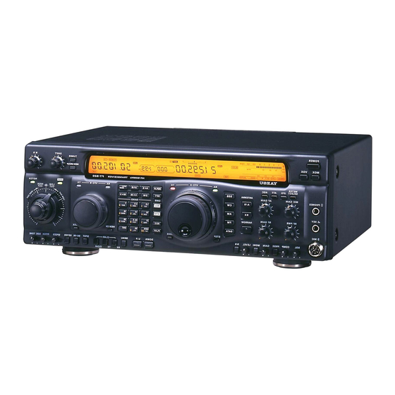
FT-920
OPERATING
MANUAL
YAESU MUSEN CO., LTD.
1-20-2 Shimomaruko, Ota-Ku, Tokyo 146-8649, Japan
YAESU U.S.A.
17210 Edwards Rd., Cerritos, CA 90703, U.S.A.
YAESU EUROPE B.V.
Snipweg 3, 1118DN Schiphol, The Netherlands
YAESU UK LTD.
Unit 12, Sun Valley Business Park, Winnall Trading Estate
Winchester, Hampshire, SO23 0LB, U.K.
YAESU GERMANY GmbH
Am Kronberger Hang 2, D-65824 Schwalbach, Germany
YAESU HK LTD.
11th Floor Tsim Sha Tsui Centre, 66 Mody Rd.,
Tsim Sha Tsui East, Kowloon, Hong Kong
Advertisement
Table of Contents

Related Manuals for Yaesu FT-920


Summary of Contents for Yaesu FT-920
- Page 1 FT-920 OPERATING MANUAL YAESU MUSEN CO., LTD. 1-20-2 Shimomaruko, Ota-Ku, Tokyo 146-8649, Japan YAESU U.S.A. 17210 Edwards Rd., Cerritos, CA 90703, U.S.A. YAESU EUROPE B.V. Snipweg 3, 1118DN Schiphol, The Netherlands YAESU UK LTD. Unit 12, Sun Valley Business Park, Winnall Trading Estate Winchester, Hampshire, SO23 0LB, U.K.
-
Page 2: Table Of Contents
Data Protocol ............ 88 General Coverage Reception ......42 Constructing Sending CAT Commands ...... 88 Dealing with Interference ........43 Downloading FT-920 Data ........... 89 Control ........... 43 14-Byte Frequency Data Record Structure ....90 HIFT Controls (DSP) ....43 Memory Backup ............... -
Page 3: General Description
Congratulations on the purchase of your Yaesu FT-920! Whether this is your first rig, or if Yaesu equipment is already the backbone of your amateur radio station, it is our sincere hope that you will derive many years of operating enjoyment from your new transceiver. - Page 4 Undesired Sideband Suppression: At least 50 dB below peak output Audio Response (SSB, DSP Off): Not more than -6 dB from 400 to 2600 Hz SSB 3rd-order IMD: -31 dB or better @ 100 Watts PEP (14 MHz) Microphone Impedance: ~ 600 FT-920 Operating Manual...
-
Page 5: Specifications
Frequency Range: 160 m ~ 6 m amateur bands Matching Time: <30 seconds Matched SWR: <1.4:1 Specifications are subject to change, in the interest of technical improvement, without notice or obligation. Specifications are guaranteed only within Amateur bands. FT-920 Operating Manual... -
Page 6: Accessories & Options
1000 Watt Solid State HF+50 MHz Linear Amplifier E-767 Band Data + T/R Switching Cable for FL-7000 RCA Connector (P/N P0090544) 2 Pin Miniature Plug (P/N P0090034) 3 Pin Phone Plug (P/N P0090008) 5 Pin DIN Plug (P/N P0091006) FT-920 Operating Manual... -
Page 7: Plug Pinout
FT-920 Operating Manual... -
Page 8: Installation
13.5 V ±10%. If you wish to use a power supply other than one of Yaesu manufacture, you must make certain that any DC supply connector to the transceiver matches the FT-920 requirements. See the DC connector pinout on the previous page. - Page 9 FT-920 Operating Manual...
-
Page 10: Transceiver Location
(not of Yaesu manufacture), while otherwise The FT-920 HF transceiver, like any other HF com- being suitable for use with the FT-920, may be de- munications apparatus, requires an effective ground signed such that the Negative (black) DC output ter- system for maximum electrical safety and best com- minal is “floating”... -
Page 11: Antenna Considerations
Any antenna to be used with the FT-920 must, ulti- Antenna Considerations mately, be fed with 50 coaxial cable. Therefore, The FT-920 is designed for use with any antenna when using a “balanced” antenna such as a dipole, system providing a 50... -
Page 12: Adjusting The Front Feet
Adjusting the Front Feet The two front feet of the FT-920 can be set in either of two positions. By turning the knurled ring around a (retracted) foot clockwise, the middle of the foot will extend about one centimeter. Turn the ring as far as it will go (about ¼... -
Page 13: Safety Precautions
DC of the support] plus [the length of any antenna or guy power connector as does Yaesu, but the wiring con- wires attached to the support] plus [the height of the figuration of the other manufacturer’s plug may be power line support pole]. -
Page 14: Rf Field Exposure Advisory And Electromagnetic Compatibility
50 Watts cabinet front panels. (maximum) via Menu Items U-49 and U-50; see page For further information, consult amateur radio refer- 79 for details. ence guides and publications relating to RFI suppres- sion techniques. FT-920 Operating Manual... -
Page 15: Accessory Installation
Most other commonly-used linear amplifiers may also mentation for your equipment. be used with the FT-920, so long as the Tx/Rx switch- þ Be absolutely certain to check the position of the ing voltages and timing (sequencing) for the switch prior to connecting any external de- amplifier’s control relay(s) are not extraordinary. - Page 16 100 Watts on the other amplifier, connect a jumper between Pin 8 and Pin 3 antenna port. (Ground); if you do not, the FT-920 will not allow it- self to transmit. Interconnection with QSK Amplifiers If using a Yaesu FL-7000 amplifier, connect the (op- If your QSK amplifier requires the exciter’s control...
- Page 17 (transistor or relay) of the FT-920 made available via the B or T As the FT-920 is supplied from the factory, the inter- jacks. Your warranty does not cover damage nal relay is disabled, and a high-dissipation NPN caused by improper interconnections to linear transistor’s (open) collector is connected to the T...
-
Page 18: Digital Modem Interfacing (Tnc, Weatherfax, Etc.)
2. Digital Modem Interfacing Connect this to the shield(s) of the cable(s) used (TNC, WeatherFax, etc.) for connections between the TNC and the FT-920. The FT-920 provides several convenient interconnec- Pin 3 (PTT): tion points, as well as dedicated operating modes, Connect this pin to the PTT line from the TNC. -
Page 19: Other Digital/Recording Device Interfacing
Pin 4 of the D jack. How- ever, the two output ports use independent output buffer amplifiers, so you can freely connect and dis- connect devices to/from these ports without concern over the impedances and levels. FT-920 Operating Manual... -
Page 20: Cw Key/Paddle And Computer Keying Interface Suggestions
Features front panel K jack, and activate the front panel The FT-920 includes a host of features for the CW switch. If you wish to keep the keyer EYER operator, the functions of which will be detailed in the paddle’s cable out of the way, connect the plug,... -
Page 21: Antenna Connections
The FT-920’s three antenna connectors, plus inno- for Contest Software, etc. vative microprocessor-based memory and switching The FT-920 features a built-in level converter, allow- circuits, provide excellent flexibility in setting up your ing direct connection from the rear-panel CAT jack to antenna connections. -
Page 22: Front Panel Controls, Switches, & Jacks
Press [MOX] once to activate the transmit This ¼” 3-pin jack is used for connection of a CW mode, and press it again to release the FT-920 back keyer paddle or a straight key. Use only a 3-pin (“ste- into the receive mode. - Page 23 DATA USB DATA FM DATA LSB on the display panel. DATA (RTTY/FS K) (PK T/AFSK) (PKT/AFS K) (RT TY/FSK) ? If “AGC O ” is selected, the S-meter (which moni- tors AGC voltage) will cease to function. FT-920 Operating Manual...
- Page 24 ” RCA connector on the rear panel of the (22) M Control FT-920. This feature allows connection of a low- This control is used to adjust the audio level of the noise receiving antenna or a VHF/UHF receive voice monitor. Clockwise rotation increases the au- converter.
- Page 25 If this LED is pushed while it is already illuminated, EVEL This control adjusts the blanking level for the IF Noise the FT-920 will be placed in the (reduced-power: Blanker. Clockwise rotation increases the degree of Approx. 10 W) “TX M ”...
- Page 26 Pressing and holding this switch in for ½ second Pressing this switch activates the Dual Watch fea- causes the contents of VFO-A to be copied into VFO- ture. B, so that the two VFOs’ contents will be identical. FT-920 Operating Manual...
- Page 27 If this LED is pushed while it is already illuminated, Pressing this switch causes the built-in Digital Re- the FT-920 will be placed in the (reduced-power: corder to start recording the contents of the receiver’s Approx. 10W) “TX MUTE” mode. In this mode, the incoming audio.
- Page 28 Tuning from VFO-A frequency) feature. When this signal will be precisely aligned to a “Zero Beat” posi- feature is activated, the VFO-B Tuning Knob is used tion relative to the other station’s signal. for Clarifier tuning up to an offset of ±9.99 kHz. FT-920 Operating Manual...
- Page 29 Notch filter. (62) T Switch UNER This is the On/Off switch for the FT-920’s Automatic Antenna Tuner. Pressing this switch momentarily places the Antenna Tuner in line. Pressing and holding in this switch for ½ second ac- tivates the Automatic Matching mode, in which a car- rier is generated and the tuner ’s microprocessor-...
-
Page 30: Display Panel Indicators And Icons
This icon is illuminated when a Narrow filter (in those This icon is illuminated when the receiver input pream- modes where one is available) has been selected. plifier is On, and it displays the number of dB of at- tenuation. FT-920 Operating Manual... - Page 31 DSP system’s bandwidth. Other configurations allow de- piction of the Clarifier offset direction and magnitude, as well as tuning accuracy. See the discussion on page 74 for details. FT-920 Operating Manual...
- Page 32 This icon is illuminated when the Memory system is restricted to the Memory Group mode. See page 61 (28) [T] for details. This icon is illuminated when the CTCSS Tone En- coder is activated during FM Repeater operation. FT-920 Operating Manual...
- Page 33 (serial) DATA port. Dur- (45) [NR] ing operation using software which “polls” the radio’s This icon is illuminated when the DSP Noise Reduc- status frequently, this icon may appear to be blink- tion circuitry is active. ing. FT-920 Operating Manual...
-
Page 34: Rear Panel Connectors And Switches
Tx/Rx com- the Yaesu Model FL-7000 Linear Amplifier. mand control of the FT-920. This jack is wired in par- allel with the front-panel MOX switch; shorting the Port... - Page 35 0V ~ -4V DC, with -4V corre- 920. sponding to the maximum degree of power reduc- (8) 13.5V Jack tion being applied to the FT-920. This jack provides +13.5V DC at up to 200 mA for (15) RX A Jacks use with low-power peripheral devices.
-
Page 36: Bottom Panel
The small adjustment hole, shown in the drawing, is used for adjustment of the “Beep” tone associated with front panel keystrokes. FT-920 Operating Manual... -
Page 37: Operation
EVEL NB L fully counter-clockwise We will now discuss antenna selection, frequency EVEL 12 o’clock navigation, and other aspects of FT-920 operation. PEED 12 o’clock ITCH Antenna Selection 12 o’clock Two main antenna jacks These represent typical starting points for operation;... -
Page 38: Mode Selection
QRM from a CW station that the IF Shift and/or DSP are unable to elimi- nate, you should try switching to the reverse CW sideband, retuning the desired CW signal, and adjust the IF Shift and/or DSP again. FT-920 Operating Manual... -
Page 39: Bandwidth Selection
Bandwidth Selection Amateur Band Selection VFO-A Band Selection Optional filters are available from your Yaesu dealer for providing selectable IF bandwidths in the CW and One-touch Amateur band selection is provided via AM modes. For CW, the optional YF-116C 500 Hz the Keypad, located between the VFO-A and VFO-B filter provides the narrow selectivity needed for today’s... -
Page 40: Direct Keypad Frequency Entry
Direct Keypad Frequency Entry Stacked VFO System VFO-A Direct Frequency Entry The FT-920 provides two VFO registers on each band A starting point on a band may also be established for each Tuning Dial (“A” and “B”). These dual regis- using direct entry via the Keypad. -
Page 41: Vfo Tuning Dial
< 0 .5 sec VFO -B Tuning Di al 100k Hz 1MHz 10kHz shown at the right. and S huttle Jog Al l Switc hes > 0 .5 sec None exp. POW ER, MOX , VOX Switc hes FT-920 Operating Manual... -
Page 42: Operating Convenience Features
The “Beep” tone which is heard when you press a Display Brightness Control key on the front panel may be adjusted, if you like. The FT-920 is shipped from the factory with the dis- play illumination set to its maximum level. Should you To adjust the Beep Frequency:... -
Page 43: Receiver Accessories
CW mode. Configuration of the Enhanced Tun- challenges to today’s operator. The FT-920, however, ing Scale is performed via Menu Item U-10 (page provides a wealth of features designed to enhance 74). -
Page 44: Agc Selection
Squelch ticular need to do so. If you wish to mute the FT-920’s receiver during no- Although the MOSFET preamplifier provides signal conditions, rotate the SQL (Squelch) control higher gain, the JFET preamplifier yields higher clockwise until the background noise just disappears. -
Page 45: Dealing With Interference
Press the [DSP] switch again to turn the DSP pass- band filter off. Note: Since the DSP passband filter operates in the audio section, after the AGC detector, very strong signals inside the IF passband but outside the DSP FT-920 Operating Manual... -
Page 46: Notch Filter (Dsp)
AGC voltage; this causes the background DSP Noise Reduction (NR) noise and signal levels to decrease, and it also causes The DSP system of your FT-920 includes a highly- the “no-signal” indication of the S-meter to rise. Sig- effective Noise Reduction circuit. The DSP Noise... -
Page 47: Tools For Strong-Signal Andlow-Frequency Operation
The NR circuit is an The FT-920 is particularly well equipped to assist the adaptive filter which “form fits” around a signal, operator in maintaining reliable communications un- so this observation is completely normal. -
Page 48: Att (Front End Attenuator)
The “0 dB” position, of course, represents the “At- tenuator Off” configuration. Digital Voice Recorder Operation (DVR) The FT-920 includes a built-in Digital Voice Recorder which you can use to record and then replay the in- coming signal (from the VFO-A path) for a period of up to 16 seconds. -
Page 49: Transmitting
Remember NTENNA nected to the antenna jack in use. Although that the net SWR as detected by the FT-920 may be the FT-920’s final amplifier protection circuitry different than the SWR at the antenna feedpoint, will drastically reduce power if no load is... - Page 50 D. The automatic antenna tuner has 100 dedicated tuner memory registers, of which eleven are allocated (one each) to the amateur bands covered by the FT-920. The other 89 record the most recent tuner settings, irrespective of the band in use, on a first-in, first-out basis.
-
Page 51: Ssb Transmission
, speak into the microphone at a normal SSB Transmission voice level. The FT-920 should automatically Basic Operation switch into the transmit mode, and should return Connect your microphone to the front panel M to receive when you quit talking. -
Page 52: Dsp Voice Pattern Contours
Digital Voice Recorder Operation (Transmit) ? Raising the compression level generally raises talk The FT-920’s Digital Voice Recorder can be used to power; however, excessive advancement of the store as many as four messages, in your own voice,... -
Page 53: Linear Amplifier Tuning
Now, when you press on the key, the trans- mitter will automatically activated, and after you quit sending the FT-920 will return to the receive mode. The “Hang Time” for the CW “VOX” cir- cuitry is adjustable (separately for the CW mode as opposed to SSB) via Menu Item U-24. -
Page 54: Electronic Keyer Operation
Memory Keyer Operation and set the rear panel’s P switch to P The FT-920 includes an easy-to-use CW Message R Confirm that the controls and switches are set up memory system, which allows automated CW send- as they were originally for Straight Key operation ing of repetitive messages (such as “CQ TEST”... -
Page 55: Tips For Successful Cw Memory Keyer Operation
Menu Item U- operation, whereby a DX-pedition station may trans- mit on one frequency while listening over a segment of the same band. The FT-920 provides several Review of Stored Messages means of efficient split frequency operations for DX... -
Page 56: Split Frequency Operation
VFO-B Tuning Dial to set Mode K Satellite Operation VFO-B somewhere between 7.210 and 7.220 Although the FT-920 is not designed for full duplex MHz (pressing [A B] ensures that both VFOs satellite operation, Mode K satellite operation (uplink are on the same operating mode). -
Page 57: Mode K Satellite Operation
AFSK-FSK switch must be set to AFSK. to check your uplink frequency before transmit- The FT-920 can also accept input from a TNC ting, as your signal may be propagated over a long or Terminal Unit (TU) operating in the FSK ( Fre-... -
Page 58: Afsk Rtty Or Packet Operation
FSK RTTY Operation the “FSK” mode properly enabled on your TNC, if This mode utilizes the tone generator in the FT-920 the software requires you to do so. for production of the required Mark and Space tones If you are having trouble decoding HF packet sta- used for RTTY operation. -
Page 59: Am Transmission
Repeater Operation ting of the M control which causes the power The FT-920 may also be used, in the FM mode, for output indication to increase slightly on voice repeater operation. Several convenient features make peaks, reduce the setting of the M control FM repeater operation simple and efficient. -
Page 60: Repeater Operation
To set the 50 MHz CTCSS Tone Mode (CTCSS/ Linear Amplifier Tuning Burst), use Menu Item U-36 (see page 77). A special feature of the FT-920 allows you to do low- To set your FT-920’s transmitted CTCSS tone duty-cycle tune-up of your linear amplifier by trans-... -
Page 61: Memory Operation
Press the [QMB RCL] key to recall the currently- ing frequency; thanks to the enhanced memory space active QMB channel. The “QMB” indicator on the provided in the FT-920, the following data will be display will become illuminated. stored into each memory channel:... -
Page 62: (Channel #1-01 To 1-99)
Tuning Dial, press the [M ] key once lost! more. Memory Channel Recall Q If you currently are in the VFO tuning mode, press the[VFO/M ] key once to enter the “Memory” FT-920 Operating Manual... -
Page 63: Memory Operation On Split-Frequency Channels
.” Memory Group Information The FT-920’s main memory area may be divided into as many as four groups. These groups may, in some instances, provide more efficient or intuitive memory operation; for example you might wish to segregate memories according to operating objectives, such as:... -
Page 64: (Channel #D-01 To D-10)
7.100 MHz, while the other station must transmit in left and right sides of the frequency display, and the 7.150 ~ 7.300 MHz range. The FT-920 provides the VFO-A and VFO-B Tx and Rx LED/Switches ten special memories for such operating instances. -
Page 65: (Channel #C-01 To C-11)
Memory Channels You may now repeat this process for the other Channels, preferably assigning one such Each of the memory channels in the FT-920, except channel per band. Note: Channel “C-10” already is programmed (at the factory) with the following frequency: C-10: 51.000.00MHz (FM) -
Page 66: Adding Alpha-Numeric Labels To Memory Channels
F] key to advance the entry position as you fill Moving Memory Data to VFO-A up the Label register, up to a maximum of seven Data stored on memory channels can easily be characters. moved to VFO-A, if you like. FT-920 Operating Manual... -
Page 67: Memory Mode Accessories
Deleting Data from a Memory Channel The FT-920 contains a wide variety of scanning ca- Frequency data stored on a memory channel can be pabilities. Whether you are in the VFO mode or one deleted from a memory channel, if desired. -
Page 68: Scanning Operation
MHz in “P-Hi.” U Press the [PTT] switch on the microphone to can- R Next, switch from the VFO mode to the Memory cel scanning and return to normal Tuning Dial mode by pressing [VFO/M operation. FT-920 Operating Manual... -
Page 69: Scan-Resume Choices
The scanner can also be programmed to stop when it finds a signal, and lock on that fre- quency without resuming the scan at some point. The scan-resume choices may be selected via Menu Item U-15 (SCN-STP); see page 75 for details. FT-920 Operating Manual... -
Page 70: Dual Watch Operation
Therefore, if the green “RX” LED for VFO-B is illumi- noise is silenced. nated when you push [DW], the FT-920 will hold on T Press the [DW] key. The decimal points in both VFO-B, then check VFO-A periodically for activity. -
Page 71: Menu Operation
R Rotate the VFO-B Tuning Dial to select the Menu lessly. The Ergonomics Design Team at Yaesu Musen Co., Ltd. therefore created the Menu System such Item you wish to work on. -
Page 72: Panel Menu Operation
Quick menu Items. r To gain access to the other “Normal” Menu Items, press [M ] and hold it in for ½ sec- ond (instead of pressing it momentarily). After you have done one of the above actions with FT-920 Operating Manual... -
Page 73: Menu Mode Selections And Settings
HF Re pea te r Ton e T yp e C TC S S/Bur st C TC S S U -3 6 V HF R e pea te r Ton e T yp e C TC S S/Bur st C TC S S FT-920 Operating Manual... - Page 74 U -7 2 AT U F as t Tu nin g On /O ff O ff U -7 3 RX Ant. Jac k Circ uit P at h Op en/C onn ec ted o n T x Ope n FT-920 Operating Manual...
- Page 75 Selecting “ ” cuts the tuning rate in half com- your own transmitted signal (in the CW mode). By pared to the default value. setting this Menu Item to On, however, you can also cause the FT-920 to transmit when the [\ ] key is SPOT U-02 ( pressed.
- Page 76 1 Hz, thanks to the 1 Hz calibration dots on the Enhanced Tuning Scale. This feature will be dis- FT-920 Operating Manual...
- Page 77 Default: (corresponds to 1:1 Dot:Space ratio) Use this Menu item to set the Dot weighting for the internal keyer. It is not recommended that you ex- ceed a value of “ ” for this setting. FT-920 Operating Manual...
- Page 78 Use this Menu Item to shorten the number “two” in a Increasing this value somewhat above its default will contest number. allow the FT-920 to stay in the “transmit” mode be- tween word spaces. This function is analogous to the U-29 ( “VOX Delay”...
- Page 79 U-37) to be transmitted continuously when the “RPT” FM mode is in use. The BURST option transmits the selected tone for an interval of only 500 milliseconds, and typically only the 1750 Hz tone selection would be applicable for BURST operation. FT-920 Operating Manual...
- Page 80 7 4.4 8 8.5 10 3.5 12 3.0 14 6.2 17 3.8 21 0.7 25 0.3 grammed via Menu Item U-42 (RTTY Tones). 7 7.0 9 1.5 10 7.2 12 7.3 15 1.4 17 9.9 21 8.1 FT-920 Operating Manual...
- Page 81 The gain of the J-FET amplifier rolls off above 30 MHz, as does the gain of the MOS FET amplifier below about 7 MHz; accordingly, we do not recom- mend these amplifiers be used outside of the recom- mended frequencies. FT-920 Operating Manual...
- Page 82 Tuning pulser via Antenna-A Available Values: Default: If you have different amplifiers for different bands, each with unique drive requirements, you may use this setting to define the tune-up power level via the A antenna port. FT-920 Operating Manual...
- Page 83 HIFT response of the receiver during USB operation. The effect of the adjustment can be heard if you turn the volume up while rotating the VFO-B Tuning Dial to adjust the setting. FT-920 Operating Manual...
- Page 84 When the CW filter is installed, the signal path must Item should be set to the point where loud speaker be enabled (or the FT-920 will not “know” that the volume does not activate the VOX. filter is there). Conversely, if the filter is not installed, erroneously setting this Menu Item to “...
- Page 85 RF voltage is afforded by a small relay which, in the default condition, opens the RX Antenna line during transmission. If only very low RF voltage is present in your installation during trans- mission, this Menu Item may be turned OFF. FT-920 Operating Manual...
-
Page 86: Vhf/Uhf Transverter Operation
Although the FT-920 does not have a dedicated Select Antenna-B by pressing the [A NTENNA “Transverter” jack per se , the flexibility provided by B] switch, if needed. the multiple antenna ports and the Menu system will Press VFO-A’s Orange “T ”... -
Page 87: Phone Pacth Operation
The pany for permission to connect an external de- FT-920 may be used with the LL-7 phone patch unit vice, such as a phone patch, to the telephone installed in the optional SP-8 external loudspeaker, system’s lines. -
Page 88: (Computer-Aided Transceiver) System Protocol
See Note 5 Mode Setting See Note 6 P=00~ FF(H) in 1 ms. steps. A dds delay between each Update IntervalPacing byte of all downlo aded data from the FT-920 Status Update See Note 7 Keyer Commands See Note 8... - Page 89 64~6D: Memory Channels d-01~d-10 (VFO-A) 82.5 118.8 173.8 28h* 1750 6E~78: Memory Channels C-01~C-11 85.4 123.0 179.9 79~7A: Memory Channels P-Lo~P-Hi 88.5 127.3 186.2 7B~84: Memory Channels d-01~d-10 (VFO-B) 91.5 131.8 192.8 * 28h = P1 only 85~89: QMB Memories S-01~S-05 FT-920 Operating Manual...
-
Page 90: Data Protocol
Opcode 03H, parameter P2 (Memory five bytes are then sent, opcode last , from the com- Set) must be set to value “00.” Therefore, the cor- puter to the FT-920 CPU via the computer’s serial responding five-byte command/parameter block port and the transceiver’s jack. -
Page 91: Downloading Ft-920 Data
These Opcodes are detailed below. Downloading FT-920 Data Status Update (10H) On command, the FT-920 will download some or all Depending on the value of parameter P1, this com- of its operational data. By regular polling of the trans- mand will return: ceiver, your software can be kept continuously up- •... -
Page 92: 14-Byte Frequency Data Record Structure
11 0.9 19 h 15 1. 4 22 h 21 0. 7 08 h 8 5. 4 11 h 11 4.8 1A h 15 6. 7 23 h 21 8. 1 * 28h = P1 o nly FT-920 Operating Manual... -
Page 93: Memory Backup
The FT-920’s memory data is maintained, even when Backup Battery Replacement DC power it turned off, via a lithium backup battery The backup battery is a standard Sony™ CR2032 with an estimated lifetime of approximately five years. (or equivalent), which is installed in a socket on the No data essential to the fundamental operation of the bottom side of the transceiver. -
Page 94: Microprocessor Resetting
Menu settings to their origi- removed, as possibly dangerous voltages may exist nal factory default values. To do this, turn the trans- inside the case. FT-920 Operating Manual... -
Page 95: Installation Of Optional Accessories
To close up the case, replace the six screws on the bottom, then tighten the four screws on the side panels. Be careful not to pinch any wires while re-assembling the radio. Figure 1 Figure 2 FT-920 Operating Manual... -
Page 96: Installation Of Optional Filters Yf-116C/Yf-116A
T Installation is now complete, as the FM-1 has been carefully aligned at the factory and should require no adjustment after installation. Replace the bot- tom case of the transceiver. FT-920 Operating Manual... - Page 97 CAUTION ! Changes or modifications to this device not expressly approved by Yaesu Musen could void the user’s authorization to operate this device. 1. This device complies with part 15 of the FCC Rules. Operation is subject to the following two conditions; (1) this device may not cause harmful interference, and (2) this device must accept any interference including interference that may cause undesired operation.
- Page 98 ..leading the way. Copyright 1997 Yaesu Musen Co., Ltd. All rights reserved. No portion of this manual may be reproduced without the permission of Yaesu Musen Co., Ltd.
Need help?
Do you have a question about the FT-920 and is the answer not in the manual?
Questions and answers