Table of Contents
Advertisement
Quick Links
Advertisement
Table of Contents

Summary of Contents for Lowrance SpotlightScan
- Page 1 SpotlightScan™ Installation Manual ENGLISH lowrance.com...
-
Page 3: Warranty
The Spotlight complies with the following regulations: • CE under EMC directive 2004/108/EC • Level 2 devices of the Radio communications (Electromagnetic • Compatibility) standard 2008 The relevant Declaration of Conformity is available in the following websites under model documentation section: www.lowrance.com. SpotlightScan | Installation Manual... -
Page 4: About This Manual
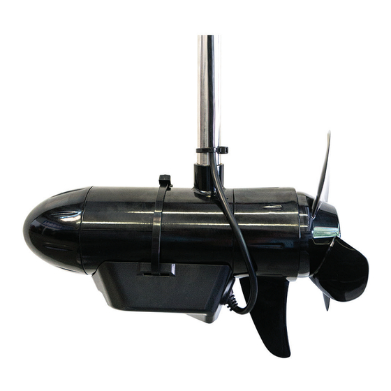
Trademarks • ‘NMEA 2000’ is a registered trademark of the National Marine Electronics Association. • ‘Navico’, ‘Lowrance’, and ‘SpotlightScan’ are trademarks of Navico, registered in the US and other countries. • ‘MotorGuide’ is a registered trademark of Brunswick Corporation. •... - Page 5 Contents SpotlightScan transducer Position sensor Roller plate Adhesive Foam pads (x4) Mounting plate No. 6 (6/32) screw No. 6 nut Hose clamp Zip ties (x2) Manual SpotlightScan | Installation Manual...
-
Page 6: Installation
If you have any concerns, have your system installed by a qualified technician. This document covers installation of the SpotlightScan system on all MotorGuide and Minn Kota cable-steer trolling motors. Warning: Disconnect power to the trolling motor before installing the SpotlightScan transducer. - Page 7 (rear view) skeg Alignment marks Rear view of the skeg lined up between alignment marks on the SpotlightScan transducer. Installing the position sensor The position sensor will be installed on the foot pedal base. It must be installed so the lever arm is in constant contact with the underside of the foot pedal.
-
Page 8: Foot Pedal Adjustment
Do not use the arrow indicator on the trolling motor head as a reference as it may not be aligned correctly with the trolling motor. Refer to the SpotlightScan operation manual for more information. - Page 9 Fasten the mounting plate to the underside of the base using the supplied No. 6 (6/32) screw and nut. Reinstall the switch on the side of the foot pedal base. Turn the foot pedal right-side up. SpotlightScan | Installation Manual...
- Page 10 Connect the position sensor cable to your NMEA 2000 network. The rib must The rib must be flush butt against the with the top edge of alignment tab. the mounting plate. SpotlightScan | Installation Manual...
- Page 11 Cable mount The wiring harness should be moved away The adhesive foam pads will be installed in the from the area where the position sensor will four cavities next to the cable mount. be installed. SpotlightScan | Installation Manual...
- Page 12 (side view). Pull the lever arm back and install the position sensor on the foot pedal base using the attached adhesive. Reinstall the base plate. Connect the position sensor to your NMEA 2000 network. 10 | SpotlightScan | Installation Manual...
- Page 13 Connect the position sensor cable to your NMEA 2000 network. The side of the sensor rib should be flush against this part of the base housing. The rib should grip this edge of the base housing. | 11 SpotlightScan | Installation Manual...
-
Page 14: Wiring Diagrams
Wiring diagrams HDS Gen2 Touch Position sensor NMEA 2000 network SpotlightScan transducer HDS Gen2 Position sensor NET-3 NET-2 NET-1 POWER 12V/24V NMEA 2000 network SonarHub TRANSDUCER1 TRANSDUCER2 SpotlightScan transducer 12 | SpotlightScan | Installation Manual...


Need help?
Do you have a question about the SpotlightScan and is the answer not in the manual?
Questions and answers