Table of Contents
Advertisement
IDEAL INDUSTRIES, INC.
TECHNICAL MANUAL
MODEL: 61-700
MODEL: 61-701
MODEL: 61-702
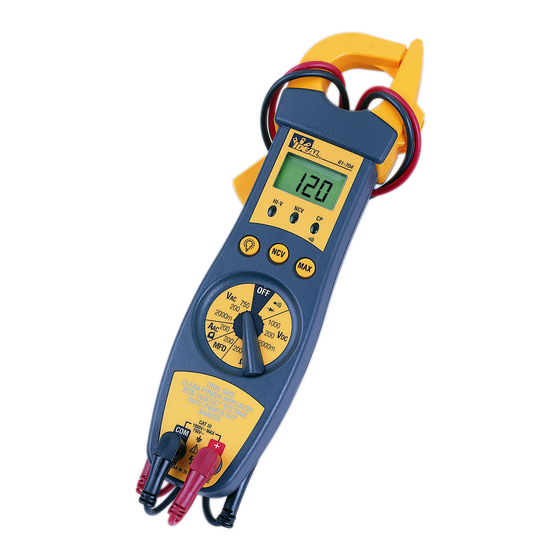
MODEL: 61-704
The Service Information provides the following information:
• Precautions and safety information
• Specifications
• Performance test procedure
• Calibration and calibration adjustment procedure
• Basic maintenance (replacing the battery)
Form number: TM61700-1-2-4
Revision: 4. Date: Sept 2004
Form number TM61700-1-2-4
Rev 4 September 2004
Advertisement
Table of Contents


Need help?
Do you have a question about the 61-704 and is the answer not in the manual?
Questions and answers