Dell DIMENSION E510 DCSM Owner's Manual
Hide thumbs
Also See for DIMENSION E510 DCSM:
- Setting-up manual (2 pages) ,
- Owner's manual (142 pages) ,
- Service manual (73 pages)
Table of Contents
Advertisement
Quick Links
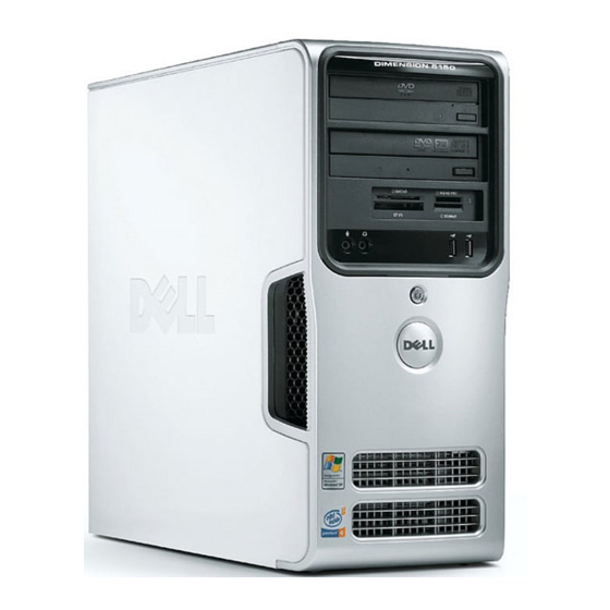
Dell™ Dimension™ 5150/E510
Service Tag
CD or DVD eject button
CD or DVD activity light
FlexBay for optional
floppy drive or Media
Card Reader
microphone connector
headphone connector
diagnostic lights
hard-drive activity light
power button/
power activity light
USB 2.0 connectors (2)
network
adapter
Model DCSM
w w w . d e l l . c o m | s u p p o r t . d e l l . c o m
Owner's Manual
power connector
sound connectors (integrated) (5)
VGA video connector (integrated)
USB 2.0 connectors (5)
card slots for PCI Express x16 (1),
PCI (2), PCI Express x1 (1)
cover latch
release
Advertisement
Table of Contents
Troubleshooting

Related Manuals for Dell DIMENSION E510 DCSM


Summary of Contents for Dell DIMENSION E510 DCSM
- Page 1 Dell™ Dimension™ 5150/E510 Owner’s Manual cover latch Service Tag release CD or DVD eject button CD or DVD activity light FlexBay for optional floppy drive or Media Card Reader microphone connector headphone connector diagnostic lights hard-drive activity light power button/ power activity light USB 2.0 connectors (2)
- Page 2 Trademarks used in this text: Dell, the DELL logo, Inspiron, Dell Precision, Dimension, OptiPlex, Latitude, PowerEdge, PowerVault, PowerApp, DellNet, and PowerConnect are trademarks of Dell Inc.; Intel and Pentium are registered trademarks of Intel Corporation; Microsoft, Windows, and Outlook are registered trademarks of Microsoft Corporation.
-
Page 3: Table Of Contents
Contents Finding Information ......Setting Up and Using Your Computer Setting Up a Printer . - Page 4 About RAID Configurations ......Determining If RAID Is Working ....RAID Level 1 .
- Page 5 Using Microsoft Windows XP System Restore ... . . Using Dell PC Restore by Symantec ....
- Page 6 Inside View of Your Computer ..... . . System Board Components ......Memory .
- Page 7 ......Dell Technical Support Policy (U.S. Only) ....
- Page 8 Contents...
-
Page 9: Finding Information
Additional documentation may be included with your computer, depending on your country. What Are You Looking For? Find it Here • Warranty information Dell™ Product Information Guide • Safety instructions • Regulatory information • Ergonomics information • End User License Agreement •... - Page 10 • Community — Online discussion with other Dell Corporate, government, and education customers customers can also use the customized Dell Premier Support website • Upgrades — Upgrade information for components, such at premier.support.dell.com. as memory, the hard drive, and the operating system •...
- Page 11 What Are You Looking For? Find it Here • How to use Windows XP Windows Help and Support Center • How to work with programs and files Click the Start button and click Help and Support. • How to personalize my desktop Type a word or phrase that describes your problem and click the arrow icon.
-
Page 13: Setting Up And Using Your Computer
Setting Up and Using Your Computer Setting Up a Printer NOTICE: Complete the operating system setup before you connect a printer to the computer. See the documentation that came with the printer for setup information, including how to: • Obtain and install updated drivers •... -
Page 14: Connecting To The Internet
USB connector on computer USB printer cable USB connector on printer Connecting to the Internet NOTE: ISPs and ISP offerings vary by country. To connect to the Internet, you need a modem or network connection and an Internet service provider (ISP), such as AOL or MSN. -
Page 15: Setting Up Internet Connection
If you do not have an MSN Explorer or AOL icon on your desktop or if you want to set up an Internet connection with a different ISP: 1 Save and close any open files, and exit any open programs. 2 Click the Start button and click Internet Explorer. -
Page 16: Playing Cds And Dvds
Playing CDs and DVDs NOTICE: Do not press down on the CD or DVD tray when you open or close it. Keep the tray closed when you are not using the drive. NOTICE: Do not move the computer when you are playing CDs or DVDs. 1 Press the eject button on the front of the drive. -
Page 17: Adjusting The Volume
A DVD player includes the following basic buttons: Stop Restart the current chapter Play Fast forward Pause Fast reverse Advance a single frame while in pause mode Go to the next title or chapter Continuously play the current title or chapter Go to the previous title or chapter Eject For more information on playing CDs or DVDs, click Help on the CD or DVD player (if available). -
Page 18: Copying Cds And Dvds
Sonic support website at www.sonic.com. The DVD-writable drives installed in Dell computers can write to and read DVD+/-R, DVD+/-RW and DVD+R DL (dual layer) media, but cannot write to and may not read DVD-RAM or DVD-R DL media. -
Page 19: Helpful Tips
Blank DVD+/-Rs can be used to permanently store large amounts of information. After you create a DVD+/-R disc, you may not be able to write to that disc again if the disc is "finalized" or "closed" during the final stage of the disc creation process. Use blank DVD+/-RWs if you plan to erase, rewrite, or update information on that disc later. -
Page 20: Using A Media Card Reader (Optional)
• Use a blank CD-RW to practice CD recording until you are familiar with CD recording techniques. If you make a mistake, you can erase the data on the CD-RW and try again. You can also use blank CD-RWs to test music file projects before you record the project permanently to a blank CD-R. •... -
Page 21: Connecting Two Monitors
xD-Picture Card and SmartMedia (SMC) CompactFlash Type I and II (CF I/II) and MicroDrive Card Memory Stick (MS/MS Pro) SecureDigital Card (SD)/ MultiMediaCard (MMC) To use the Media Card Reader: 1 Check the media or card to determine the proper orientation for insertion. 2 Slide the media or card into the appropriate slot until it is completely seated in the connector. -
Page 22: Connecting Two Monitors With Vga Connectors
Connecting Two Monitors With VGA Connectors 1 Follow the procedures in "Before You Begin" on page 59. NOTE: If your computer has integrated video, do not connect either monitor to the integrated video connector. If the integrated video connector is covered by a cap, do not remove the cap to connect the monitor or the monitor will not function. -
Page 23: Connecting A Tv
Connecting a TV NOTE: You must purchase an S-video cable, available at most consumer electronics stores, to connect a TV to your computer. It is not included with your computer. 1 Follow the procedures in "Before You Begin" on page 59. 2 Connect one end of the S-video cable to the optional TV-OUT connector on the back of the computer. -
Page 24: Network Setup Wizard
network adapter network device connector network adapter connector on computer network cable Network Setup Wizard ® ® The Microsoft Windows XP operating system provides a Network Setup Wizard to guide you through the process of sharing files, printers, or an Internet connection between computers in a home or small office. -
Page 25: Standby Mode
Because hibernate mode requires a special file on your hard drive with enough disk space to store the contents of the computer memory, Dell creates an appropriately sized hibernate mode file before shipping the computer to you. If the computer’s hard drive becomes corrupted, Windows XP recreates the hibernate file automatically. - Page 26 3 Under or pick a Control Panel icon, click Power Options. 4 Define your power settings on the Power Schemes tab, Advanced tab, and Hibernate tab. Power Schemes Tab Each standard power setting is called a scheme. If you want to select one of the standard Windows schemes installed on your computer, choose a scheme from the Power schemes drop-down menu.
-
Page 27: Hyper-Threading
The drives should be the same size to ensure that the larger drive does not contain unallocated (and therefore unusable) space. NOTE: If you purchased your Dell computer with RAID, your computer has been configured with two hard drives that are the same size. Setting Up and Using Your Computer... -
Page 28: Determining If Raid Is Working
Determining If RAID Is Working Your computer displays information pertaining to your RAID configuration at startup, before loading the operating system. If RAID is not configured, the message none defined will be displayed under RAID Volumes, followed by a list of the physical drives installed in your system. If a RAID volume is identified, you can then check the Status field to determine the current state of your RAID configuration. -
Page 29: Troubleshooting Raid
Troubleshooting RAID You can use one of two methods to troubleshoot RAID hard drive volumes. One method uses the Intel RAID Option ROM utility and is performed before you install the operating system onto the hard drive. The second method uses the Intel Matrix Storage Manager, or Intel Matrix Storage Console, and is performed after the operating system and the Intel Matrix Storage Console have been installed. -
Page 30: Setting Your Computer To Raid-Enabled Mode
Setting Your Computer to RAID-Enabled Mode 1 Enter system setup (see "System Setup" on page 109). 2 Press the up- and down-arrow keys to highlight Drives, and press <Enter>. 3 Press the up- and down-arrow keys to highlight SATA Operation, and press <Enter>. 4 Press the left- and right-arrow keys to highlight RAID On, press <Enter>, and then press <Esc>. -
Page 31: Solving Problems
— If you have to repeatedly reset time and date information after turning on the computer, or if an incorrect time or date displays during start-up, replace the battery (see "Replacing the Battery" on page 101). If the battery still does not work properly, contact Dell (see "Contacting Dell" on page 122). -
Page 32: Cd And Dvd Drive Problems
U N T H E E L L I A G N O S T I C S — See "Dell Diagnostics" on page 49. CD and DVD drive problems NOTE: High-speed CD or DVD drive vibration is normal and may cause noise, which does not indicate a defect in the drive or the CD or DVD. -
Page 33: Hard Drive Problems
U R N O F F T A N D B Y M O D E I N I N D O W S B E F O R E W R I T I N G T O A C D / D V D - R W D I S C —... -
Page 34: Error Messages
U N T H E O D E M E L P E R D I A G N O S T I C S — Click the Start button, point to All Programs, and then click Modem Helper. Follow the instructions on the screen to identify and resolve modem problems. (Modem Helper is not available on all computers.) E R I F Y T H A T T H E M O D E M I S C O M M U N I C A T I N G W I T H I N D O W S... -
Page 35: Media Card Reader Problems
If so, run the program that you want to use first. P E R A T I N G S YS T E M N O T F O U N D — Contact Dell (see "Contacting Dell" on page 122). Media Card Reader Problems O D R I V E L E T T E R I S A S S I G N E D —... -
Page 36: Lockups And Software Problems
H E C K T H E K E Y B O A R D C A B L E — • Ensure that the keyboard cable is firmly connected to the computer. • Shut down the computer (see "Turning Off Your Computer" on page 59), reconnect the keyboard cable as shown on the setup diagram for your computer, and then restart the computer. -
Page 37: A Program Stops Responding
A program stops responding N D T H E P R O G R A M — Press <Ctrl><Shift><Esc> simultaneously. Click Applications. Click the program that is no longer responding. Click End Task. A program crashes repeatedly NOTE: Software usually includes installation instructions in its documentation or on a floppy disk or CD. H E C K T H E S O F T W A R E D O C U M E N T A T I O N —... -
Page 38: Other Software Problems
(see "Installing Memory" on page 70). • Reseat the memory modules (see "Installing Memory" on page 70) to ensure that your computer is successfully communicating with the memory. • Run the Dell Diagnostics (see "Dell Diagnostics" on page 49). Solving Problems... -
Page 39: Mouse Problems
• Ensure that you are following the memory installation guidelines (see "Installing Memory" on page 70). • Your computer supports DDR2 memory. For more information about the type of memory supported by your computer, see "Memory" on page 105. • Run the Dell Diagnostics (see "Dell Diagnostics" on page 49). Mouse Problems CAUTION: Before you begin any of the procedures in this section, follow the safety instructions in the Product Information Guide. -
Page 40: Network Problems
Network Problems CAUTION: Before you begin any of the procedures in this section, follow the safety instructions in the Product Information Guide. H E C K T H E N E T W O R K C A B L E C O N N E C T O R —... -
Page 41: Printer Problems
F T H E P O W E R L I G H T I S O F F — The computer is either turned off or is not receiving power. • Reseat the power cable into both the power connector on the back of the computer and the electrical outlet. -
Page 42: Scanner Problems
N S U R E T H A T T H E P R I N T E R I S T U R N E D O N H E C K T H E P R I N T E R C A B L E C O N N E C T I O N S —... -
Page 43: Sound And Speaker Problems
E R I F Y T H A T T H E S C A N N E R I S R E C O G N I Z E D B Y I C R O S O F T I N D O W S —... -
Page 44: No Sound From Headphones
E I N S T A L L T H E S O U N D D R I V E R — See "Manually Reinstalling Drivers" on page 52. U N T H E A R D W A R E R O U B L E S H O O T E R —... -
Page 45: If The Screen Is Difficult To Read
If the screen is difficult to read H E C K T H E M O N I T O R S E T T I N G S — See the monitor documentation for instructions on adjusting the contrast and brightness, demagnetizing (degaussing) the monitor, and running the monitor self-test. O V E T H E S U B W O O F E R A W A Y F R O M T H E M O N I T O R —... - Page 46 Solving Problems...
-
Page 47: Troubleshooting Tools
• If available, install properly working memory of the same type into your computer (see "Installing Memory" on page 70). • If the problem persists, contact Dell (see "Contacting Dell" on page 122). Troubleshooting Tools... - Page 48 • If available, install properly working memory of the same type into your computer (see "Installing Memory" on page 70). • If the problem persists, contact Dell (see "Contacting Dell" on page 122). Memory modules are detected, • Ensure that no special memory...
-
Page 49: Dell Diagnostics
Before you begin any of the procedures in this section, follow the safety instructions in the Product Information Guide. If you experience a problem with your computer, perform the checks in "Solving Problems" on page 31 and run the Dell Diagnostics before you contact Dell for technical assistance. Troubleshooting Tools... -
Page 50: Dell Diagnostics Main Menu
If you cannot resolve the error condition, contact Dell (see "Contacting Dell" on page 122). NOTE: The Service Tag for your computer is located at the top of each test screen. If you contact Dell, technical support will ask for your Service Tag. -
Page 51: Drivers
Parameters Allows you to customize the test by changing the test settings. 4 Close the test screen to return to the Main Menu screen. To exit the Dell Diagnostics and restart the computer, close the Main Menu screen. Drivers What Is a Driver? A driver is a program that controls a device such as a printer, mouse, or keyboard. -
Page 52: Reinstalling Drivers
Reinstalling Drivers NOTICE: The Dell Support website at support.dell.com provides approved drivers for Dell™ computers. If you install drivers obtained from other sources, your computer might not work correctly. Using Windows XP Device Driver Rollback If a problem occurs on your computer after you install or update a driver, use Windows XP Device Driver Rollback to replace the driver with the previously installed version. -
Page 53: Resolving Software And Hardware Incompatibilities
• Dell PC Restore by Symantec restores your hard drive to the operating state it was in when you purchased the computer. Dell PC Restore permanently deletes all data on the hard drive and removes any applications installed after you received the computer. Use PC Restore only if System Restore did not resolve your operating system problem. - Page 54 NOTE: The procedures in this document were written for the Windows default view, so they may not apply if you set your Dell™ computer to the Windows Classic view. Creating a Restore Point 1 Click the Start button and click Help and Support.
-
Page 55: Using Dell Pc Restore By Symantec
Using Dell PC Restore by Symantec NOTICE: Using Dell PC Restore permanently deletes all data on the hard drive and removes any applications or drivers installed after you received your computer. If possible, back up the data before using PC Restore. Use PC Restore only if System Restore did not resolve your operating system problem. - Page 56 NOTICE: Removing Dell PC Restore from the hard drive permanently deletes the PC Restore utility from your computer. After you have removed Dell PC Restore, you will not be able to use it to restore your computer’s operating system. Dell PC Restore enables you to restore your hard drive to the operating state it was in when you purchased your computer.
-
Page 57: Using The Operating System Cd
The Operating System CD provides options for reinstalling Windows XP. The options can overwrite files and possibly affect programs installed on your hard drive. Therefore, do not reinstall Windows XP unless a Dell technical support representative instructs you to do so. - Page 58 Troubleshooting Tools...
-
Page 59: Removing And Installing Parts
You have performed the steps in "Turning Off Your Computer" on page 59 and "Before Working Inside Your Computer" on page 59. • You have read the safety information in your Dell™ Product Information Guide. • A component can be replaced or—if purchased separately—installed by performing the removal procedure in reverse order. - Page 60 NOTICE: Only a certified service technician should perform repairs on your computer. Damage due to servicing that is not authorized by Dell is not covered by your warranty. NOTICE: When you disconnect a cable, pull on its connector or on its strain-relief loop, not on the cable itself.
-
Page 61: Front View Of The Computer
Computer Cover" on page 65. location of Service Tag Use the Service Tag to identify your computer when you access the Dell Support website or call technical support. CD or DVD eject button Press to eject a disk from the CD or DVD drive. - Page 62 diagnostic lights (4) Use the lights to help you troubleshoot a computer problem based on the diagnostic code. For more information, see "Diagnostic Lights" on page 47. hard-drive activity light The hard drive activity light is on when the computer reads data from or writes data to the hard drive.
-
Page 63: Back View Of The Computer
Back View of the Computer voltage selection switch (may not See the safety instructions in the Product Information Guide for more be available on all computers) information. power connector Insert the power cable. back panel connectors Plug USB, audio, and other devices into the appropriate connector. card slots Access connectors for any installed PCI and PCI Express cards. - Page 64 link integrity light • Green — A good connection exists between a 10-Mbps network and the computer. • Orange — A good connection exists between a 100-Mbps network and the computer. • Off — The computer is not detecting a physical connection to the network. network adapter To attach your computer to a network or broadband device, connect one end of a connector...
-
Page 65: Removing The Computer Cover
center/subwoofer Use the yellow connector to attach a speaker to a Low Frequency Effects (LFE) connector audio channel. VGA video connector If your monitor has a VGA connector, plug it into the VGA connector on the computer. USB 2.0 connectors (5) Use the back USB connectors for devices that typically remain connected, such as printers and keyboards. - Page 66 cover latch release computer cover back of computer bottom hinges 4 Locate the three hinge tabs on the bottom edge of the computer. 5 Grip the sides of the computer cover and pivot the cover up, using the bottom hinges as leverage points.
-
Page 67: Inside View Of Your Computer
Inside View of Your Computer CAUTION: Before you begin any of the procedures in this section, follow the safety instructions in the Product Information Guide. Follow the procedures in "Before You Begin" on page 59. power supply system board CD or DVD drive *floppy drive hard drive *May not be present on all computers. -
Page 68: System Board Components
System Board Components processor connector (CPU) password jumper (PSWD) power connector (12V) processor fan connector (FAN) memory module connectors (2, 4) memory module connectors (1, 3) floppy drive battery socket connector (DSKT2) (BATTERY) RTC reset jumper (RTCRST1) PCI connectors (2) SATA connector (SATA2) PCI Express x16... -
Page 69: Memory
Memory You can increase your computer memory by installing memory modules on the system board. Your computer supports DDR2 memory. For additional information on the type of memory supported by your computer, see "Memory" on page 105. DDR2 Memory Overview DDR2 memory modules should be installed in pairs of matched memory size, speed, and technology. -
Page 70: Addressing Memory With 4-Gb Configurations
If you remove your original memory modules from the computer during a memory upgrade, keep them separate from any new modules that you may have, even if you purchased the new modules from Dell. If possible, do not pair an original memory module with a new memory module. Otherwise, your computer may not start properly. - Page 71 memory connector closest to processor securing clips (2) connector 4 Align the notch on the bottom of the module with the crossbar in the connector. notch memory module cutouts (2) crossbar NOTICE: To avoid damage to the memory module, press the module straight down into the connector while you apply equal force to each end of the module.
-
Page 72: Removing Memory
You can do so by touching an unpainted metal surface on the computer chassis. Your Dell™ computer provides the following slots for PCI and PCI Express cards: • Two PCI card slots •... -
Page 73: Pci Cards
PCI Cards Your computer supports two PCI cards. If you are installing or replacing a card, follow the procedures in the next section. If you are removing but not replacing a PCI card, see "Removing a PCI Card" on page 76. If you are replacing a card, remove the current driver for the card from the operating system. - Page 74 4 If you are replacing a card that is already installed in the computer, remove the card. If necessary, disconnect any cables connected to the card. Grasp the card by its top corners, and ease it out of its connector. 5 Prepare the card for installation.
- Page 75 alignment guide alignment bar release tab card retention door 8 Close the card retention door by snapping it into place to secure the card(s). NOTICE: Do not route card cables over or behind the cards. Cables routed over the cards can prevent the computer cover from closing properly or cause damage to the equipment.
-
Page 76: Pci Express Cards
3 If you are removing the card permanently, install a filler bracket in the empty card-slot opening. If you need a filler bracket, contact Dell (see "Contacting Dell" on page 122). NOTE: Installing filler brackets over empty card-slot openings is necessary to maintain FCC certification of the computer. - Page 77 Installing a PCI Express Card 1 Follow the procedures in "Before You Begin" on page 59. card retention door card retention mechanism release tabs (2) 2 Gently push the release tab on the card retention door from the inside to pivot the door open. Because the door is captive, it will remain in the open position (see "Installing a PCI Card"...
- Page 78 PCI Express PCI Express x1 card x16 card securing tab PCI Express x1 card slot PCI Express x16 card slot 6 Prepare the card for installation. See the documentation that came with the card for information on configuring the card, making internal connections, or otherwise customizing it for your computer.
- Page 79 9 If you replaced a card that was already installed in the computer and you removed the retention mechanism, you may reinstall the retention mechanism. 10 Before replacing the card retention mechanism, ensure that: • The tops of all cards and filler brackets are flush with the alignment bar. •...
-
Page 80: Drive Panel
Set the retention mechanism aside in a secure location. 4 If you are removing the card permanently, install a filler bracket in the empty card-slot opening. If you need a filler bracket, contact Dell (see "Contacting Dell" on page 122). NOTE: Installing filler brackets over empty card-slot openings is necessary to maintain FCC certification of the computer. -
Page 81: Removing The Drive Panel
Removing the Drive Panel 1 Follow the procedures in "Before You Begin" on page 59. sliding plate lever sliding plate drive panel 2 Grasping the lever on the sliding plate, pull the sliding plate to the right until it snaps into the open position. -
Page 82: Removing The Drive-Panel Insert
Removing the Drive-Panel Insert drive panel insert tab drive panel drive panel insert 1 Turn the drive panel sideways and find the tip of the drive-panel insert tab that latches over a tab on the right side of the drive panel. 2 Pull the inner tip of the drive-panel insert tab away from the drive panel. -
Page 83: Replacing The Drive Panel
Replacing the Drive Panel. 1 Follow the procedures in "Before You Begin" on page 59. sliding plate lever sliding plate drive panel 2 Align the drive panel tabs with the side-door hinges. 3 Rotate the drive panel toward the computer until it snaps into place on the front panel. Drives Your computer supports a combination of these devices: •... -
Page 84: Ide Drive Addressing
CD/DVD drive(s) FlexBay for optional floppy drive or Media Card Reader hard drive(s) Connect CD/DVD drives to the connector labeled "IDE1" on the system board. Serial ATA hard drives should be connected to the connectors labeled "SATA0" or "SATA2" on the system board. IDE Drive Addressing When you connect two IDE devices to a single IDE interface cable and configure them for the cable select setting, the device attached to the last connector on the interface cable is the master or boot... -
Page 85: Drive Interface Connectors
Drive Interface Connectors Most interface connectors are keyed for correct insertion; that is, a notch or a missing pin on one connector matches a tab or a filled-in hole on the other connector. Keyed connectors ensure that the pin- 1 wire in the cable (indicated by the colored stripe along one edge of the IDE cable—serial ATA cables do not use a colored stripe) goes to the pin-1 end of the connector. -
Page 86: Hard Drive
Like IDE connectors, the serial ATA interface connectors are keyed for correct insertion; that is, a notch or a missing pin on one connector matches a tab or a filled-in hole on the other connector. Hard Drive CAUTION: Before you begin any of the procedures in this section, follow the safety instructions in the Product Information Guide. -
Page 87: Installing A Hard Drive
serial ATA data cable power cable 3 Press in on the blue tabs on each side of the drive and slide the drive up and out of the computer. tabs (2) hard drive Installing a Hard Drive 1 Unpack the replacement hard drive, and prepare it for installation. 2 Check the documentation for the drive to verify that it is configured for your computer. - Page 88 drive hard drive bracket 3 Gently slide the drive into place until you feel a click or feel the drive securely installed. 4 Connect the power and hard-drive cables to the drive. serial ATA data cable power cable 5 Check all connectors to be certain that they are properly cabled and firmly seated. 6 Replace the computer cover (see "Replacing the Computer Cover"...
-
Page 89: Adding A Second Hard Drive
Adding a Second Hard Drive CAUTION: Before you begin any of the procedures in this section, follow the safety instructions in the Product Information Guide. CAUTION: To guard against electrical shock, always unplug your computer from the electrical outlet before removing the cover. -
Page 90: Floppy Drive
Floppy Drive CAUTION: Before you begin any of the procedures in this section, follow the safety instructions in the Product Information Guide. CAUTION: To guard against electrical shock, always unplug your computer from the electrical outlet before removing the cover. NOTE: If you are adding a floppy drive, see "Installing a Floppy Drive"... -
Page 91: Installing A Floppy Drive
drive latch release sliding plate floppy drive Installing a Floppy Drive NOTE: In the event the replacement or new floppy drive does not have the shoulder screws, use the screws located within the drive panel insert. Removing and Installing Parts... - Page 92 drive screws (4) 1 Follow the procedures in "Before You Begin" on page 59. 2 Remove the drive panel (see "Removing the Drive Panel" on page 81). 3 Gently slide the drive into place until you feel a click or feel the drive securely installed. NOTE: If you are installing a new floppy drive rather than replacing a drive, remove the drive panel insert where you want the drive to be installed, insert the shoulder screws located in the back of the drive panel insert into the...
- Page 93 11 Enter system setup (see "System Setup" on page 109) and select the appropriate Diskette Drive option. 12 Verify that your computer works correctly by running the Dell Diagnostics (see "Dell Diagnostics" on page 49). Removing and Installing Parts...
-
Page 94: Media Card Reader
Media Card Reader For information on using the Media Card Reader, see "Using a Media Card Reader (Optional)" on page 20. Removing a Media Card Reader CAUTION: Before you begin any of the procedures in this section, follow the safety instructions located in the Product Information Guide. - Page 95 5 Disconnect the FlexBay USB cable on the back of the Media Card Reader from the Media Card Reader connector on the system board (see "System Board Components" on page 68) and route the cable through the cable routing clip. drive latch release sliding plate Media Card Reader...
-
Page 96: Installing A Media Card Reader
Installing a Media Card Reader CAUTION: Before you begin any of the procedures in this section, follow the safety instructions located in the Product Information Guide. NOTICE: To prevent static damage to components inside your computer, discharge static electricity from your body before you touch any of your computer’s electronic components. -
Page 97: Cd/Dvd Drive
FlexBay USB cable Media Card Reader 8 Insert the Media Card Reader and slide it into place until it is fully seated. 9 Route the FlexBay USB cable through the cable routing clip. 10 Replace the computer cover (see "Replacing the Computer Cover" on page 102). CD/DVD Drive CAUTION: Before you begin any of the procedures in this section, follow the safety instructions located in the... - Page 98 power cable data cable 5 Slide the drive latch release toward the bottom of the computer and, without releasing the drive latch release, slide the CD/DVD drive out through the front of the computer. Removing and Installing Parts...
-
Page 99: Installing A Cd/Dvd Drive
drive latch release sliding plate CD/DVD drive Installing a CD/DVD Drive 1 Follow the procedures in "Before You Begin" on page 59. 2 If you are installing a new CD/DVD drive rather than replacing a drive, remove the drive-panel inserts (see "Removing the Drive-Panel Insert"... - Page 100 CD/DVD drive screws (4) 4 Connect the power and data cables to the drive. power cable data cable Removing and Installing Parts...
-
Page 101: Battery
See the documentation that came with the drive for instructions on installing any software required for drive operation. 9 Enter system setup (see "System Setup" on page 109) and select the appropriate Drive option. 10 Verify that your computer works correctly by running the Dell Diagnostics (see "Dell Diagnostics" on page 49). Battery... -
Page 102: Replacing The Computer Cover
4 Remove the battery by carefully prying it out of its socket with your fingers or with a blunt, nonconducting object such as a plastic screwdriver. 5 Insert the new battery into the socket with the side labeled "+" facing up, and snap the battery into place. - Page 103 computer cover back of computer bottom hinges 5 Ensure that the cover is seated correctly before moving it to the upright position. NOTICE: To connect a network cable, first plug the cable into the network device and then plug it into the computer.
- Page 104 Removing and Installing Parts...
-
Page 105: Appendix
Appendix Specifications Processor ® ® Processor type Intel Pentium 4 with Hyper-Threading technology NOTE: Not all Pentium 4 processors support Hyper-Threading technology. Level 1 (L1) cache 32 KB Level 2 (L2) cache 1 MB (depending on your computer configuration) pipelined- burst, eight-way set associative, write-back SRAM Memory Type... - Page 106 Video Type Integrated Intel Graphics Media Accelerator 950 (GMA950) Audio Type Sigmatel STAC9220 Expansion Bus Bus type PCI 2.3 PCI Express x1 and x16 Bus speed PCI: 33 MHz PCI Express: x1 slot bidirectional speed - 500 MB/s x16 slot bidirectional speed - 8 GB/s connectors connector size 120 pins...
- Page 107 Connectors External connectors: Video 15-hole connector Network adapter RJ-45 connector two front-panel and five back-panel USB 2.0-compliant connectors Audio five connectors for line-in, line-out, microphone/ side-surround, surround, and center/subwoofer connector (LFE channel); two front-panel connectors for headphones and microphone System board connectors: Primary IDE drive one 40-pin connector on PCI local bus Serial ATA...
- Page 108 Controls and Lights (continued) Diagnostic lights four lights on the front panel (see "Diagnostic Lights" on page 47.) Standby power light AUX_PWR on the system board Power DC power supply: Wattage 305 W Heat dissipation 560.5 BTU/hr Voltage (see the safety instructions 90 to 135 V and 180 to 265 V at 50/60 Hz located in the Product Information Guide for important voltage setting...
-
Page 109: System Setup
Entering System Setup 1 Turn on (or restart) your computer. 2 When the blue DELL™ logo is displayed, you must watch for the F2 prompt to appear. 3 Once this F2 prompt appears, press <F2> immediately. NOTE: The F2 prompt indicates that the keyboard has initialized. -
Page 110: System Setup Options
System Setup Options NOTE: Depending on your computer and installed devices, the items listed in this section may not appear, or may not appear exactly as listed. System Displays the System name, BIOS Version number, BIOS Date, Service Tag, System Info Express Service Code, and Asset Tag. - Page 111 Displays the amount of Installed Memory, Memory Speed, Memory Memory Info Channel Mode, and a description of the Memory Technology. This option also displays a table that describes the memory size, whether the memory module is ECC capable, single or dual rank, type, and organization. Displays the contents of each PCI slot.
- Page 112 Onboard Devices Enables or disables the integrated NIC controller. Settings are On, Off, or On Integrated NIC w/PXE. When the On w/PXE setting is active (available only for setting up (On default) a future boot process), the computer prompts you to press <Ctrl><Alt><b>.
- Page 113 • Bypass — Your computer does not test or change the current acoustics HDD Acoustic Mode mode setting. • Quiet — The hard drive operates at its most quiet setting. • Suggested — The hard drive operates at the level suggested by the drive manufacturer.
- Page 114 Sets the computer to automatically turn on. Auto Power On • Off — disables the Auto Power On feature (Off default) • Everyday — turns the computer on every day at the time set in Auto Power Time • Weekdays — turns the computer on every day from Monday through Friday at the time set in Auto Power Time NOTE: This feature does not work if you turn off your computer using a power...
-
Page 115: Boot Sequence
Determines whether the sign-on screen displays a message stating the POST Hotkeys keystroke sequence that is required to enter the Setup program or the (Setup & Boot Menu Quickboot feature. default) • Setup & Boot Menu — displays both messages (F2=Setup and F12=Boot Menu) •... - Page 116 2 Turn on (or restart) your computer. 3 When F2 = Setup, F12 = Boot Menu appears in the upper-right corner of the screen, press <F12>. If you wait too long and the operating system logo appears, continue to wait until you see the Microsoft Windows desktop.
-
Page 117: Clearing Forgotten Passwords
Clearing Forgotten Passwords CAUTION: Before you begin any of the procedures in this section, follow the safety instructions located in the Product Information Guide. 1 Follow the procedures in "Before You Begin" on page 59. 2 Locate the 3-pin password jumper (PSWD) on the system board (see "System Board Components" on page 68), and attach the jumper plug to pins 2 and 3 to clear the password. -
Page 118: Clearing Cmos Settings
7 Disconnect the computer power cable from the electrical outlet, and press the power button to ground the system board. 8 Open the computer cover (see "Removing the Computer Cover" on page 65). 9 Locate the 3-pin password jumper (PSWD) on the system board (see "System Board Components" on page 68) and attach the jumper to pins 1 and 2 to reenable the password feature. -
Page 119: Mouse
NOTICE: Do not wipe the display screen with any soap or alcohol solution. Doing so may damage the antiglare coating. • To clean your monitor screen, lightly dampen a soft, clean cloth with water. If possible, use a special screen-cleaning tissue or solution suitable for the monitor’s antistatic coating. •... -
Page 120: Dell Technical Support Policy (U.s. Only)
All Dell-standard components included in a Custom Factory Integration (CFI) project are covered by the standard Dell lim- ited warranty for your computer. However, Dell also extends a parts replacement program to cover all nonstandard, third- party hardware components integrated through CFI for the duration of the computer’s service contract. -
Page 121: Class A
Once you have determined your system’s FCC classification, read the appropriate FCC notice. Note that FCC regulations provide that changes or modifications not expressly approved by Dell could void your authority to operate this equipment. This device complies with Part 15 of the FCC Rules. Operation is subject to the following two conditions: This device may not cause harmful interference. -
Page 122: Fcc Identification Information
In certain countries, technical support specific to Dell XPS portable computers is available at a separate telephone number listed for participating countries. If you do not see a telephone number listed that is specific for XPS portable computers, you may contact Dell through the technical support number listed and your call will be routed appropriately. - Page 123 Tech Support Services toll-free: 0-800-444-0724 Sales 0-810-444-3355 Aruba General Support toll-free: 800-1578 Australia (Sydney) E-mail (Australia): au_tech_support@dell.com International Access Code: 0011 E-mail Customer Care (Australia and New Zealand): apcustserv@dell.com Country Code: 61 Home and Small Business 1-300-655-533 City Code: 2...
- Page 124 Country Code: 32 Technical Support for XPS portable computers only 02 481 92 96 City Code: 2 Technical Support for all other Dell computers 02 481 92 88 Technical Support Fax 02 481 92 95 Customer Care 02 713 15 65...
- Page 125 Country Code: 673 Customer Care (Penang, Malaysia) 604 633 4888 Transaction Sales (Penang, Malaysia) 604 633 4955 Canada (North York, Ontario) Online Order Status: www.dell.ca/ostatus International Access Code: 011 AutoTech (automated technical support) toll-free: 1-800-247-9362 Customer Care (Home Sales/Small Business) toll-free: 1-800-847-4096 Customer Care (med./large business, government)
- Page 126 Country Code: 86 Technical Support E-mail: cn_support@dell.com City Code: 592 Customer Care E-mail: customer_cn@dell.com Technical Support Fax 592 818 1350 Technical Support (Dell™ Dimension™ and toll-free: 800 858 2969 Inspiron™) Technical Support (OptiPlex™, Latitude™, and toll-free: 800 858 0950 Dell Precision™)
- Page 127 Website: support.euro.dell.com International Access Code: 00 E-mail: support.euro.dell.com/dk/da/emaildell/ Country Code: 45 Technical Support for XPS portable computers only 7010 0074 Technical Support for all other Dell computers 7023 0182 Customer Care (Relational) 7023 0184 Home/Small Business Customer Care 3287 5505...
- Page 128 Country Code: 33 Home and Small Business City Codes: (1) (4) Technical Support for XPS portable computers only 0825 387 129 Technical Support for all other Dell computers 0825 387 270 Customer Care 0825 823 833 Switchboard 0825 004 700...
- Page 129 Website: support.ap.dell.com International Access Code: 001 Technical Support E-mail: apsupport@dell.com Country Code: 852 Technical Support (Dimension and Inspiron) 2969 3188 Technical Support (OptiPlex, Latitude, and Dell 2969 3191 Precision) Technical Support (PowerApp™, PowerEdge™, 2969 3196 PowerConnect™, and PowerVault™) Customer Care...
- Page 130 Country Code: 353 Technical Support for XPS portable computers only 1850 200 722 City Code: 1 Technical Support for all other Dell computers 1850 543 543 U.K. Technical Support (dial within U.K. only) 0870 908 0800 Home User Customer Care...
- Page 131 Technical Support outside of Japan (Dimension and 81-44-520-1435 Inspiron) Technical Support (Dell Precision, OptiPlex, and toll-free:0120-198-433 Latitude) Technical Support outside of Japan (Dell Precision, 81-44-556-3894 OptiPlex, and Latitude) Technical Support (PDAs, projectors, printers, toll-free: 0120-981-690 routers) Technical Support outside of Japan (PDAs,...
- Page 132 Transaction Sales (Xiamen, China) 29 693 115 Malaysia (Penang) Website: support.ap.dell.com International Access Code: 00 Technical Support (Dell Precision, OptiPlex, and toll-free: 1 800 880 193 Latitude) Country Code: 60 Technical Support (Dimension, Inspiron, and toll-free: 1 800 881 306...
- Page 133 Website: support.euro.dell.com International Access Code: 00 Technical Support for XPS portable computers only 020 674 45 94 Country Code: 31 Technical Support for all other Dell computers 020 674 45 00 City Code: 20 Technical Support Fax 020 674 47 66...
- Page 134 Website: support.euro.dell.com International Access Code: 00 E-mail: support.euro.dell.com/no/no/emaildell/ Country Code: 47 Technical Support for XPS portable computers only 815 35 043 Technical Support for all other Dell products 671 16882 Relational Customer Care 671 17575 Home/Small Business Customer Care 23162298...
- Page 135 International Access Code: 005 Technical Support (Dimension, Inspiron, and toll-free: 1800 394 7430 Electronics and Accessories) Country Code: 65 Technical Support (OptiPlex, Latitude, and Dell toll-free: 1800 394 7488 Precision) Technical Support (PowerApp, PowerEdge, toll-free: 1800 394 7478 PowerConnect, and PowerVault)
- Page 136 Area Codes, International Access Code Website and E-Mail Address Local Numbers, and Country Code Toll-Free Numbers City Code South Africa (Johannesburg) Website: support.euro.dell.com International Access Code: E-mail: dell_za_support@dell.com 09/091 Gold Queue 011 709 7713 Country Code: 27 Technical Support 011 709 7710...
- Page 137 E-mail: support.euro.dell.com/se/sv/emaildell/ Country Code: 46 Technical Support for XPS portable computers only 0771 340 340 City Code: 8 Technical Support for all other Dell products 08 590 05 199 Relational Customer Care 08 590 05 642 Home/Small Business Customer Care...
- Page 138 Local Numbers, and Country Code Toll-Free Numbers City Code Thailand Website: support.ap.dell.com International Access Code: 001 Technical Support (OptiPlex, Latitude, and Dell toll-free: 1800 0060 07 Precision) Country Code: 66 Technical Support (PowerApp, PowerEdge, toll-free: 1800 0600 09 PowerConnect, and PowerVault)
- Page 139 1-888-798-7561 Software and Peripherals Sales toll-free: 1-800-671-3355 Spare Parts Sales toll-free: 1-800-357-3355 Extended Service and Warranty Sales toll-free: 1-800-247-4618 toll-free: 1-800-727-8320 Dell Services for the Deaf, Hard-of-Hearing, or toll-free: 1-877-DELLTTY Speech-Impaired (1-877-335-5889) U.S. Virgin Islands General Support 1-877-673-3355 Venezuela...
- Page 140 Appendix...
-
Page 141: Index
Index CD/DVD drive (continued) installing, 99 audio. See sound Dell problems, 32 contacting, 122 removing, 97 Dell Diagnostics, 49 CD-RW drive support policy, 120 problems, 32 support site, 10 battery CDs, 18 diagnostic lights, 47 problems, 31 playing, 16 replacing, 101... - Page 142 DVD drive cover, 61 removing, 86 problems, 32 lights hardware DVDs, 18 back of computer, 47 Dell Diagnostics, 49 playing, 16 diagnostic, 47, 62 Hardware Troubleshooter, 53 hard drive activity, 62 headphone connector, 61 Help and Support Center, 11 e-mail...
- Page 143 44 PC Restore, 55 computer crashes, 36-37 clone mode, 23 computer stops responding, 36 PCI cards connect DVI, 21-22 Dell Diagnostics, 49 installing, 73 connect TV, 21, 23 diagnostic lights, 47 removing, 76 connect two, 21-22 drives, 31 PCI Express cards...
- Page 144 107 new computer, 27 reinstalling controls and lights, 107 Windows XP , 53 troubleshooting drives, 106 Dell Diagnostics, 49 environmental, 108 diagnostic lights, 47 expansion bus, 106 Hardware Troubleshooter, 53 memory, 105 Help and Support Center, 11 safety instructions, 9...
- Page 145 wizards Files and Settings Transfer vents, 62 Wizard, 27 front panel, 62 Network Setup Wizard, 24 volume Program Compatibility adjusting, 43 Wizard, 37 warranty information, 9 Windows XP Device Driver Rollback, 52 Files and Settings Transfer Wizard, 27 Hardware Troubleshooter, 53 Help and Support Center, 11 Hyper-Threading, 27 Network Setup Wizard, 24...
- Page 146 Index...
Need help?
Do you have a question about the DIMENSION E510 DCSM and is the answer not in the manual?
Questions and answers