Table of Contents
Advertisement
Advertisement
Table of Contents

Subscribe to Our Youtube Channel
Related Manuals for Icom IC-F5022


Summary of Contents for Icom IC-F5022
- Page 1 INSTRUCTION MANUAL VHF MOBILE TRANSCEIVER iF5022 UHF MOBILE TRANSCEIVER iF6022...
-
Page 2: Explicit Definitions
IC-F6022 UHF MOBILE TRANSCEIVER. NOTE of personal injury, fire or electric shock. Icom, Icom Inc. and the Icom logo are registered trademarks of Icom Incor- porated (Japan) in Japan, the United States, the United Kingdom, Germany, France, Spain, Russia and/or other countries. -
Page 3: Precautions
Icom transceiver. snow or any liquids. Icom is not responsible for the destruction or damage to an Icom transceiver in the event the Icom transceiver is used the specified microphone only. Other microphones have with equipment that is not manufactured or approved by different pin assignments and may damage the transceiver. -
Page 4: Table Of Contents
TABLE OF CONTENTS IMPORTANT ................i 3 CONNECTION AND MAINTENANCE ....14−16 EXPLICIT DEFINITIONS ............i ■ Rear panel connection ..........14 PRECAUTIONS ..............ii ■ Supplied Accessories ..........15 TABLE OF CONTENTS ............iii ■ Mounting the transceiver ..........15 ■ Antenna ..............16 1 PANEL DESCRIPTION ..........1−6 ■... -
Page 5: Panel Description
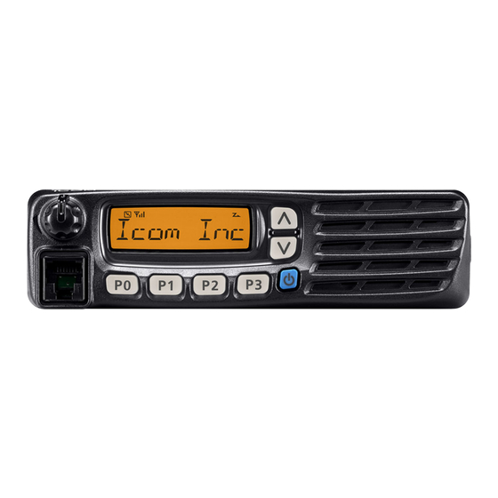
PANEL DESCRIPTION ■ Front panel Function display (p. 2) Speaker q AF VOLUME CONTROL KNOB [VOL] t MICROPHONE CONNECTOR Rotate the knob to adjust the desired audio output level. Connect the supplied or optional microphone. • Minimum audio level is pre-set. (p. 11) NEVER connect non-specified microphones. -
Page 6: Function Display
PANEL DESCRIPTION ■ Function display y SCRAMBLER INDICATOR Appears when the voice scrambler function is activated. u BELL INDICATOR Appears/blinks when the specific 2/5-tone/MDC* code is received, according to the pre-programming. i SCAN INDICATOR Blinks during scan. q TRANSMIT INDICATOR o ALPHANUMERIC DISPLAY Appears while transmitting. -
Page 7: Programmable Function Keys
[P0], [P1], [P2] and [P3] programmable function keys. • When Power ON Scan function is activated, push to pause the Consult your Icom dealer or system operator for details con- scanning operation. And the paused scan resumes after the cerning your transceivers programming. - Page 8 PANEL DESCRIPTION PRIO A/B KEYS LOCK KEY ➥ Push to select Priority A or Priority B channel. Push and hold to electronically lock all programmable keys ➥ Push and hold [Prio A (Rewrite)] or [Prio B (Rewrite)] for except the following: 1 sec.
- Page 9 PANEL DESCRIPTION WIDE/NARROW KEY EMERGENCY KEY Push to toggle the IF bandwidth between wide and narrow. Push and hold this for specified period to transmit an emer- • The wide passband width can be selected from 25.0 or 20.0 kHz gency call.
- Page 10 PANEL DESCRIPTION TX CODE CHANNEL SELECT KEY USER SET MODE KEY ➥ Push to enter the TX code channel selection mode. Then ➥ Push and hold for 1 sec. to enter user set mode. set the desired channel using [CH Up]/[CH Down]. (p. 9) •...
-
Page 11: Basic Operation
BASIC OPERATION ■ Turning power ON ■ Channel selection q Push [ ] to turn the power ON. Several types of channel selections are available. Methods w If the transceiver is programmed for a start up password, may differ according to your system set up. input the digit codes as directed by your dealer. -
Page 12: Call Procedure
BASIC OPERATION ■ Call procedure ■ Receiving and transmitting Receiving: When your system employs tone signaling (excluding q Push and hold [ ] for 1 sec. to turn the power ON. CTCSS and DTCS), a call procedure may be necessary w Push [CH Up] or [CH Down] to select a channel, in se- prior to voice transmission. -
Page 13: D Transmitting Notes
BASIC OPERATION D Transmitting notes D TX code channel selection • Transmit inhibit function If the transceiver has [TX Code CH Select] assigned to it, The transceiver has several inhibit functions which restrict the indication can be toggled between the operating channel transmission under the following conditions: number (or name) and TX code channel number (or name). -
Page 14: D Dtmf Transmission
BASIC OPERATION D TX code number edit USING [TX CODE ENTER] KEY: (PMR operation only) q Push [TX Code Enter] to enter the TX code edit mode. If the transceiver has [TX Code CH Select] or [TX Code • The digit to be edited blinks. Enter] assigned to it, TX code contents can be edited within w Push [TX Code Enter] to select the desired digit to be ed- the allowable digits. -
Page 15: User Set Mode
BASIC OPERATION ■ User Set mode ■ Emergency transmission If the transceiver has [User Set Mode] assigned to it, you The emergency call can be performed using [Emergency]. (p. 5) can “customize” the transceiver operation to suit your prefer- When [Emergency] is pushed for the specified time period, ences and operating style. -
Page 16: Scrambler Function
BASIC OPERATION ■ Scrambler function ■ Stun function The voice scrambler function provides private communica- When the specified ID, set as a stun ID or kill ID, is received, tion between stations. the stun function is activated. The optional Rolling or Non-rolling type can be available. When the stun ID is received, the transceiver becomes unusable. -
Page 17: Mdc 1200 System Operation
Emergency MDC 1200 system command once or repeat- An additional feature of MDC 1200 system found in Icom edly for a programmed number of times until it receives the transceivers is called aliasing. Each transceiver on the system acknowledgement signal. -
Page 18: Connection And Maintenance
CONNECTION AND MAINTENANCE ■ Rear panel connection q ANTENNA CONNECTOR e MICROPHONE HANGER Antenna Connects to an antenna. Contact Connect the supplied micro- your dealer about antenna selec- phone hanger to the vehicle’s tion and placement. ground for microphone on/off hook functions. -
Page 19: Supplied Accessories
CONNECTION AND MAINTENANCE ■ Supplied Accessories ■ Mounting the transceiver The universal mounting bracket supplied with your trans- Microphone Microphone hanger Microphone ceiver allows overhead mounting. and screw set hanger cable • Mount the transceiver securely with the 4 supplied screws to a thick surface which can support more than 1.5 kg. -
Page 20: Antenna
CONNECTION AND MAINTENANCE ■ Antenna ■ Options A key element in the performance of any communication • OPC-1939 acc cable systems is an antenna. Contact your dealer for more infor- Allows you to connect to an external terminal. mation regarding antennas and how to install them. •... -
Page 21: Country Code List
Romania France Slovakia Germany Slovenia Greece Spain Hungary Sweden Iceland Switzerland Ireland Turkey Italy United Kingdom Latvia About e-marking: Detailed installation notes for Icom mobile transceivers to be fitted into vehicles are available. Please contact your Icom dealer or distributor. - Page 22 MEMO...
- Page 23 MEMO...
- Page 24 < Intended Country of Use > A-6732D-1EU-e Printed in Japan © 2009–2013 Icom Inc. 1-1-32 Kamiminami, Hirano-ku, Osaka 547-0003, Japan Printed on recycled paper with soy ink.
Need help?
Do you have a question about the IC-F5022 and is the answer not in the manual?
Questions and answers